Transcription
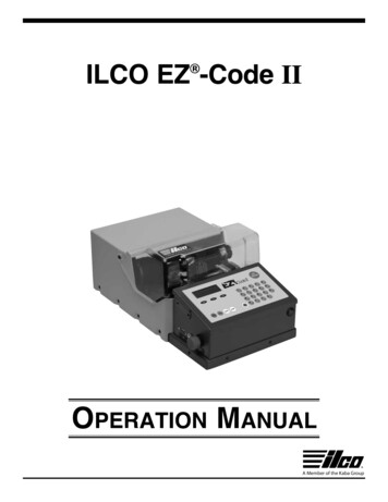
ILCO EZ -Code II Operation ManualA Member of the Kaba Group
ILCO EZ -Code IIOperation ManualThis manual has been produced to serve as a guide for users of the Ilco EZ -Code IIelectronic key-cutting machine. Read it carefully . This is essential for safe effective operation of your machine! If necessary, you can contact Kaba Ilco TechnicalAssistance for further information at 1-800-334-1381 (option 8).ContentsThis manual is divided into sections relating to Machine DescriptionTransportMachine Installation and PreparationSet Up and Use of the MachineOperation ProceduresError Messages/Machine ResetCleaningMaintenanceCutter ReplacementReplacement Parts and AccessoriesAssistanceIlco EZ -Code II Design-A-Key InstructionsSection 1Section 2Section 3Section 4Section 5Section 6Section 7Section 8Section 9Section 10Section 11Page 33TECHNICAL TERMS Certain technical terms are used in this manual. To assistthose with little experience of keys and key-cutting, below is a brief list of theterms most frequently used.Shoulder Stop- Feature found on many keys used to limit how far the keyenters a lock; normally located on the blade area of the key somewhat nearits bow (head).Tip Stop- Some keys do not have a Shoulder Stop as described above; thesekeys rely upon their tip surface to limit how far they will enter a lock.Key Stop- Term used for the machine feature required to properly positionShoulder Stop and Tip Stop keys within the machine’s Vise Jaw. There aretwo types of Key Stops used on this machine (Key Stop Tools 1&2 and theKey Gage)Card Number- The numeric identification of specific electronic files storedwithin the machine’s database, used by the machine to determine the detailsassociated with cutting various keysIndirect Code Number- The number sometimes associated with a specificlock that is used to “look up” the key cut numbers required to create a functional key for the lock. An example of an Indirect Code can be found on the“key tag” often accompanying keys supplied with a new motor vehicle.Direct Code or Bitting Number- Key cut numbers; example: a Direct Codefor a key having six cuts along its blade will consist of six digits, each of whichcorresponds to one of the six cuts.2
ILCO EZ -Code IIOperation ManualGENERALUSE: The Ilco EZ -Code II is designed for cutting keys of non-ferrousmaterial: brass, nickel-silver, zinc, etc. It must be installed and usedaccording to the instructions provided in this manual. If used for purposes other than those described, the customer forgoes any rightsthey may have over Kaba Ilco Corp.INCORRECT USE: Improper use of this machine or failure of theoperator to observe the instructions written in this manual will void all guaranteesand responsibilities of the manufacturer. Furthermore, unforeseen danger to theoperator or third parties may arise from incorrect use of the machine!It is therefore essential to carefully read and understand this operation manual.VERY IMPORTANT!SPECIAL CAUTION CONCERNING THE ELECTRICAL CONTACT FEATURE:When decoding a key, the Ilco EZ -Code II uses a low voltage circuit to detect keybitting information. certain rules apply regarding proper use: NEVER attempt to use the Ilco EZ -Code II to duplicate from a paintedor plastic pattern key! The pattern key could become damaged, and nolonger function in its intended lock. It is recommended that anodized (colored) aluminum keys should not be cut.MACHINE IDENTIFICATION The machine is provided with an identification label on its back panel whichshows the machine’s unique serial number.Model #/Serial Tag3
ILCO EZ -Code II1.Operation ManualMACHINE DESCRIPTIONThe Ilco EZ -Code II is a two-axis electronic machine with microprocessorcontrolled carriage movement. The machine is designed to combine a highdegree of cutting precision with efficient operation and ease of use. The IlcoEZ -Code II can be used to cut keys in several different ways: Making duplicate keys from a functional original Originating automotive keys based on a key code number (indirect code).Key codes are typically found on a tag accompanying a vehicle’s originalkeys and usually available to auto dealers based on vehicle VIN number. Originating an automotive or commercial/residential key based on bittingnumber (direct code) Interfacing with a PC equipped with Kreate-A-Key code software; thisallows for cutting keys by key code for older automotive applications, aswell as for padlocks, desk locks, etc. (Refer to instructions included withthe Kreate-A-Key Interface Kit - BK0338XXXX.)1.1 MAIN CHARACTERISTICS Carriage Transport MovementMovement of the two axes (X-Y) by means of precision lead screwsactivated by microprocessor controlled stepper motors. Vise Jaw“Sure Grip” two-position vise jaw, specially designed to grip most commercial, automotive and residential keys without the need for adapters. CutterAITiN coated HSS (high speed steel), that is easy to replace. An optional carbide cutter is available for cutting harder key materials and longer service life DisplayRear-illuminated LCD display screen; positioned on the machine for easyviewing. Display field is 4 rows of 20 characters each.1.2 SAFETY General Safetyu Do not use your Ilco EZ -Code II key machine for purposes notspecifically covered in this manualu Do not operate the machine in a damp environmentu Do not operate the machine with any safety enclosure or shieldremovedu Do not attempt to bypass or defeat the safety shield switches or othersafety features built into the Ilco EZ -Code IIu Do not open the main circuit box (located beneath the Touch pad andLCD display screen). There are no user serviceable parts inside, andunfastening the lid assembly will expose the operator to hazardousvoltages and sensitive electronic circuitry. Opening the circuit boxassembly will void the machine warranty!4
ILCOILCOEZEZ-Code-CodeIIOperation Manual Emergency Stop SwitchThe red emergency shut off switch, located on theleft-hand side of the machine, is used to stop the IlcoEZ -Code II immediately in the event of faulty operation or danger to the operator (press in to activate).When the cause of the emergency has been eliminated, turn the button 45 clockwise to deactivate it.The button will extend further out from the machinewhen deactivated.NOTE: the operator is responsible for keepingthe area around the button clear so that it can bereached and activated quickly in the event of anemergency. Circuit BreakerA Circuit Breaker is located adjacent to theEmergency Stop Switch, providing protectionagainst most major overload scenarios. If theCircuit Breaker activates, its center button willprotrude out from the edge of the machine circuitbox. To re-set, turn the machine Power Switch tothe off position, and press in on the breaker’s center button. If it again activates with the machineswitched on, contact the Ilco Technical ServiceDept.Press in on Emergency Stop Switch toactivate emergency stop.Side view of Main Circuit Box Cutter drive motor protectionThe cutter drive motor is protected against overheating by an internal cutout switch. Should the switch activate:1) Turn the machine off and disconnect the power supply cable. Machinewill reset after motor has cooled sufficiently.2) If machine does not reset: contact Ilco Technical Assistance at 1-800334-1381 (option 8) Protective ShieldThe transparent protective shield is designed tocover the working parts of the Ilco EZ -Code IIas completely as possible, helping ensure operator safety. Do not attempt to bypass the shield’ssafety interlock switch or attempt to operate themachine with the shield removed.5
ILCO EZ -Code IIOperation Manual1.3 MAIN WORKING PARTSA: Main Power SwitchB: Emergency Stop SwitchC: Safety ShieldD: Clamping KnobE: Two-Position Vise JawF: Touch pad KeyboardG. Main Circuit BoxH: Circuit BreakerI: USB PortCEFDIHBGAB1.4 TECHNICAL DATAPower Requirement: 2.6 Amp. 300 WattsCutter drive motor: single speed, single phaseCutter: Standard:T-U01 (AITiN coated high speed steel)Optional: D405933ZZ (carbide cutter)Jaw: “Secure Grip” 2- position vise jaw; accommodates most commercial/residential, automotive, and flat keysDimensions: 10.5” W X 19.5” D X 9” H (14” with shield raised)Weight:: 52 lbs (23.6 kg)1.5 ACCESSORIES PROVIDEDThe Ilco EZ -Code II comes with various accessories needed for its operation and maintenance (tools, hex wrenches, calibration keys) comprising:ABEGFDC6A: Cutter Spindle WrenchB: Cutter Nut WrenchC: Allen Wrench (large)D: Allen Wrench (small)E: Key Stop ToolF: Shim PinG. EZ3 Calibration Gage Keys
ILCOILCOEZEZ-Code-CodeIIOperation Manual2TRANSPORTThe Ilco EZ -Code II is not excessively heavy, but when boxed, we recommend that it be moved using at least two people.2.1 PACKAGINGThe special pre-formed foam packaging and carton used to ship your IlcoEZ -Code II is designed to protect the machine and its various componentsduring shipment.2.2 UNPACKINGAfter removing the machine and accessories from the carton, check for thefollowing contents:1 Ilco EZ -Code II key-cutting machine1 set of documents, including: an Operation Manual, a spare parts list,Quick Start Guide, Card Reference /Application Guide, 1 tool set and awarranty card. Important: The Warranty Card must be filled out andreturned to Ilco in order to receive direct notification concerningnew software updates!NOTE: For maximum protection, we strongly recommend that youretain the packaging (foam and carton) to use for any future transporting of the machine.2.3 CHECKING FOR DAMAGEThe Ilco EZ -Code II is solidly constructed, and should not become damagedif reasonable care is exercised during transit, and the unpacking and installation have all been carried out according to the instructions in this manual.However, it is always advisable to visibly check for damage prior to placingany machine product in operation. Concealed damage resulting fromrough handling during shipment must be reported to the appropriatedelivery service immediately to preserve your rights of recovery! KabaIlco will not be held responsible for damage incurred during shipment.2.4 MACHINE HANDLINGWhen the Ilco EZ -Code II has been unpacked, carefully place it in itsintended work space. Carefully lift the machine, firmly holding the base, andno other part. Do not drag the machine, the rubberized feet could potentiallybecome damaged.3.MACHINE INSTALLATION AND PREPARATIONThe Ilco EZ -Code II can be installed by the machine owner, and does notrequire any special skills. It is supplied ready for use and should not needany special set up. (extremely rough handling during shipment may however require that the machine be recalibrated for proper performance)7
ILCO EZ -Code IIOperation Manual3.1 ENVIRONMENTAL CONDITIONSTo ensure proper performance of the Ilco EZ -Code II, it is important toplace it in a well ventilated area which is not too damp. The ideal conditionsfor the machine are:Temperature between 50 F (10 C) to 104 F (40 C)Relative humidity: 60% or lower3.2 POSITIONING AND INSTALLATIONPlace the machine on a horizontal surface, solid enough to support a weightof 52 lbs. or greater. As a practical matter, we suggest that the workbench be approximatelythe height of the operator’s hip. It is important to leave clearance of at least 8” behind the machine andon each side to ensure proper ventilation. Be certain to maintain sufficientclearance to assure easy access to the Emergency Stop Switch on the leftside of the Ilco EZ -Code II. Ensure that the machine’s voltage requirement matches that of the mainpower supply (which must also be properly grounded). As with all electronic equipment, a quality surge suppression device is highly recommended especially important when using an inverter or generator asthe machine power source. Mobile installation involves additional considerations all equipmentinstalled in a mobile service vehicle must be securely fastened down tohelp minimize the possibility of personal injury or product damage in caseof traffic accident or other mishap.3.3 DESCRIPTION OF WORK STATIONThe machine requires only one operator, having easy access to the following machine controls Power switch; located on the front of the machine Vise jaw Keyboard Display Emergency shut off switch4SET UP AND USE OF THE MACHINE4.1 KEYBOARD AND FUNCTIONSThe machine’s keyboard has 19 alphanumeric and 9 function keys. Thealphanumeric keys are used for entering the data card number and thecutting data (numbers and/or letters) according to the code on the cardin use. Each of the 19 alphanumeric keys contains two characters: themain character (black) which is directly active, and an alternate character(red), which can be activated by simultaneously pressing the SHIFT key.8
ILCO EZ -Code IIOperation ManualTouch pad Keyboard andLCD Display ScreenFUNCTION KEYS:STOP key: Stops the function in progress at any time during the operation; also used to access the prior screen displayed on the LCD display.Please note that the STOP button is not an alternative to using theEmergency Shut Off Switch! Use the Emergency Shut Off Switch anytime there appears to be a risk of personal injury or machine damage withcontinued machine operation!QUIT PROCESS key: Stops machine function only.START key: Initiates the machine’s cutting operation.UP/DOWN keys: Scrolls curser thru screen options.SHIFT key: Provides access to RED letters on the keyboard; Press it incombination with the desired letter key to enter the red letterALPHA/NUMERIC keys: For providing numeric and alphabetical inputENTER key: Activation of various functions in the menu, especially to confirm input and menu screen selections.CLEAR key: deletes numerical characters.MENU / CODE / CARD keys: Convenience “hot keys” that will immediatelytake user to the indicated menu screens4.2 CLAMPING KEYS USING THE ILCO EZ -CODE II VISE JAWThe process of clamping a key in a key machine vise jaw requires that theoperator both utilize a Vise Jaw setting appropriate for gripping the key, andto position the key laterally within the jaw using an appropriate Key Stopmethod (discussed in 4.3).The Ilco EZ -Code II Vise Jaw features two clamping positions (A and B),and is uniquely designed to accommodate the vast majority of keys withoutthe need for adapters. Some keys will require the useof adapters or shim pins in order to be securely heldor to be held level in the vise jaw. Examples are: theGeneral Motors “Z” keyway and the Toyota TR47 keyblank both require adapters so that the key will lay flatin the vise jaw. To change the vise position, first loosen the ClampingKnob several turns and then lift up on the vise jawassembly as a unit to rotate it to the desired setting. In most circumstances, the machine display screen Rotation of the Vise Jawprovides guidance as to which clamping position (A orB) is most suitable for the key you’ve selected to cut.9
ILCO EZ -Code IIOperation Manual Side A is generally used for clamping single sided keys, and certaindouble-sided types that don’t have a “milling groove”. Side B is used to clamp the majority of double-sided keys. It features aspecial “V-shaped” gripping surface which is intended to grip a key byclamping into its milling groove. After correctly positioning a key within the Vise Jaw, re-tighten theClamping Knob to secure it. Only moderate tightening is required do not“over tighten” the Clamping Knob.The Ilco EZ -Code II Vise Jaw also features twoslots on each side (identified by either a Red orWhite dot). These slots are used in conjunctionwith a removable “Key Stop” accessory to positionkeys that don’t feature a shoulder stop. The use ofthe slots is discussed in more detail in section 4.3.Close up of vise jaw (removed for clarity)IMPORTANT!!! Use the supplied chip removal brushto keep the Vise Jaw surfaces free of key shavings(chips). It is a good practice to brush off the grippingsurfaces after each key to assure that chip buildupdoesn’t impact performance or accuracy.Brushing chips from Vise Jaw surfacesSingle Sided KeyDouble Sided Key with Milling GrooveDouble Sided key w/o Milling GrooveUsing A PositionUsing B PositionUsing A Position4.3 POSITIONING KEYS (Use of Key Stops)Once the proper jaw setting and gripping manner has been determined, thenext step is clamping a key into the key machine Vise Jaw. This involvesselecting the proper Key Stop method (to appropriately position the keylaterally within the jaw). The correct choice for a given key will appearon the LCD display screen and is also listed in the accompanying CardReference /Application Guide. The choices available are 0, Red, and White.10
ILCO EZ -Code IIOperation ManualKeys with shoulder stopsShoulder StopKeys without shoulder stopsTip Stop Key Stop 0: Used only for positioning keys that have shoulder stops.Rotate the machine’s Key Gage upward so that the shoulder of the keybeing clamped can be positioned against its left edge. While maintainingthis contact, tighten the Clamping Knob to secure the key.Rotate the Key Gage FULLY to the down position. You should be ableto feel the Key Gage reach a slight detent when it is in the down position.IMPORTANT! If the Key Gage is not returned FULLY to the downposition, the stepper motor will not allow the cutter to engage thekey blank. You may receive the following error message when youattempt to decode or cut a key – ERROR OPERATION ABORTED TOAVOID CONTACT WITH JAW. If this happens, you will need to turn offthe machine, ensure that the Key Gage is fully in the down position andre-start the machine in order to clear the error message.Key Gage in DownpositionKey Gage in Up positionPosition Key using KeyGageRotating Key GageCorrectly positioned. Note:Key’s shoulder must be incontact with Key Gage11
ILCO EZ -Code IIOperation Manual Key Stop R (Red) and Key Stop W (White): Used only for positioningkeys without shoulder stops. Place the accessory Key Stop Tool in theappropriate vise jaw slot (refer to display screen). Position the key withinthe Vise Jaw so that its TIP is in contact with left edge of the Key StopTool (see illustration). While maintaining this contact, tighten the ClampingKnob to secure the key. 2.CAUTION! Be sure to remove the Key StopTool from the vise jaw before attempting to cut the key. Failure to removethe Key Stop Tool could result in personal injury and/or damage to themachine.Using Key Stop Tool toKey Stop slots on Viseposition “shoulderless” KeyJaw4.4 POSITIONING KEYS (Use of Shim Pins)If you are attempting to cut a single sided key that has a narrow bladewidth or a single sided key that requires a deep cut, you may see thefollowing prompt on the screen – “DEEP CUT! USE SHIM PIN” (thesoftware that drives the Ilco EZ -Code II will determine when the ShimPin is needed based on depth of cut). If you receive this prompt itwill require the placement of a Shim Pin behind the key blade in theVise Jaw to prevent the cutter from making contact with the Vise Jaw.Included in the accessory pack with the machine are two 1.7mm ShimPins to be used to shim the key in the Vice Jaw. Place the Shim Pinbehind the Key in the Vice Jaw and then position the key using theproper Key Stops. Once you have the key tightened in the Vise Jawslide the Shim Pin out from behind the key. The width of the Shim Pinis programmed into the software for those cards that require its use, soit is important to use only the 1.7mm pin for shimming the keys. Use ofa shim of another dimension could cause you to cut a key that will notwork in the lock. The shim pin can also be used to level out keys whoseprofiles make it difficult to lay flat in the vise jaw. With some keys youcan place the shim pin in one of the millinggrooves of the key to help hold it flat in thevise jawCAUTION! If the thickness of the keyprevents the removal of the Shim Pinprior to cutting, make sure it does notprotrude excessively from the Jaw andinterfere with the travel of the Spacing Shim Pin placement on singleCarriage.sided key12
ILCO EZ -Code IIOperation Manual4.5 ELECTRICAL CONTACTThe Ilco EZ -Code II key-cutting machine is equipped with a low voltage electricalcontact circuit that is used for decoding keys and calibration of the machine. It isimportant to understand that the cutter must be free of all shavings prior to attemptingto decode a key. If there are shavings hanging from the cutter’s edge it could causecontact to be detected prior to the cutter actually making contact with the key blade.As a result, the decoded depths will be too shallow and result in a non-functional key.With the electrical contact feature, depth calibration is automatically calculated formany of the key types covered in the Ilco EZ -Code II database when the cuttertouches the key’s edge at the beginning of the cutting process. Electrical contact isassured for keys made of brass, nickel silver, or zinc (with or without nickel plating).Improper use of electric contact NEVER attempt to use the Ilco EZ -Code II to duplicate from a paintedor plastic pattern key! The pattern key could become damaged and nolonger function properly in its intended lock.4.6 INTERNAL DATABASEThe machine’s internal database includes electronic “cards” essentially,individual data files that provide the machine with specific information on howto cut specific key types. When you select a card number prior to cutting a particular key, the machine references the card’s corresponding data file to obtaininformation necessary for cutting the key.The internal database also includes key codes (indirect codes) used with popular automotive key applications.The entire database is stored on an easily replaceable SD type memory card, greatlysimplifying the process of updating the machine’s software no computer or specialcable required! Updates to the machine’s database are periodically offered as newlocking systems enter the market. These are sold through your Kaba Ilco distributor.Updating instructions are included with each memory card update.Once again, you are reminded that you must return the WarrantyRegistration Card to receive direct notification concerning the releaseof new software updates for your Ilco EZ -Code II.4.7 CUTTERThe majority of keys require that the Ilco EZ -Code II’s standard cutter(T-U01) be used. Provisions will exist in a future software release to allow forusing optional cutter configurations for specialized applications. To replacethe cutter see Section 4.7 and 4.8.For increased service life when cutting harder than normal key blank materials, a carbide cutter is available. (Ilco part# D405933ZZ) This cutter can besubstituted for the standard cutter.To assure proper performance and prevent potential machine damage useonly ILCO original replacement cutters!13
ILCO EZ -Code II5.Operation ManualOPERATION PROCEDURESIntroductionThe Operation Guide explains below how to use the Ilco EZ -Code II instand-alone mode (without a Personal Computer). All of the steps requiredto operate the machine are explained in sequence. Refer to section 4 abovefor guidance pertaining to vise jaw and key blank positioning (vise positionand key stop selection).An optional way to operate the Ilco EZ -Code II is to interface the machinewith a computer running Ilco Kreate-A-Key code software (sold separately). This allows for cutting not just popular automotive keys by indirectcode, but also keys for older vehicle applications and thousands of othertypes (padlocks, desk locks, commercial keys, etc).When operating the machine in this manner, the user will see a differencein the Ilco EZ -Code II screen information displayed. Some proceduresand functions described in this Operation Manual are eliminated, and oncethe computer’s data has been transmitted to the machine, it bypassessome of the normally appearing operation guide screens which the use ofthe Kreate-A-Key program renders unnecessary.5.1 INITIAL OPERATIONSWhen the key-cutting machine has been placed in the selected work areaand connected to an appropriate power source (Ch.3.2), proceed as follows:1) Make sure that the emergency shut off button is not activated (seeCh.1.2).2) Turn the machine on by means of the main power switch located on thefront of the unit.3) The LCD display screen will illuminate and display the Main Menu. TheUp/Down keyboard buttons will navigate the cursor through the menu.Selections are made by pressing the Enter button.VERY IMPORTANT: The balance of Chapter 5 explains how to cut keysby duplication, indirect code, and direct code. Procedures common toeach method, such as how to clamp keys using the Ilco EZ -Code II’svise jaw, and how to properly position them using the available key stopmethods (gauging), are covered in sections 4.2 and 4.3 above.Main menu012345614Duplicate KeyCut by CardCut by CodeQueue from PCDesign-A-KeyCalibrationOptions
ILCO EZ -Code IIOperation ManualOperational keys:Use the arrow keys to move the main menu cursor (*) to the option required,and press ENTER or directly press the numbered key corresponding to theoption number.5.2 [0] Duplicate a Key(Refer to 4.2 and 4.3 for Vise Jaw and Key Stop information)This function enables the user to create a duplicate key when an existingkey is available and the appropriate Ilco card number is known. TheIlco EZ -Code II will decode the existing key, and replicate the cut patternonto a blank key. The Ilco EZ -Code II Card Reference/Application Guideprovides a listing of all available Ilco card numbers, and the associated lockmanufacturers they correspond to. Card numbers are typically very specificto a given manufacturer, and in many cases, also to specific lock productsthey produce. The proper card number must be selected prior to thedecoding process; using an incorrect card number for a given key willresult in a duplicate that will not function in the intended lock.Main menu*0123456Duplicate KeyCut by CardCut by CodeQueue from PCDesign-A-KeyCalibrationOptionsOperational keys:Use the arrow keys to move the main menu cursor (*) to the option required,and press ENTER or directly press the numbered key corresponding to theoption number.1. Select the “Duplicate Key” function from the Main Menu.Cut by DuplicationEnter Ilco Card#For Pattern Key:15
ILCO EZ -Code IIOperation Manual2. Select “0” USE CARD DEPTHS to decode and cut new key to OEM specifications or “1” USE MEASURED DEPTHS to decode and cut new key todepths measured from the decoded key.*0. Use Card Depths1. Use Meas. Depths3. Type in the required card number (refer to Ilco EZ -Code II CardReference/Application Guide) and press ENTERNote: Some card numbers require that you specify how many bittings (cuts)are on the pattern key. In these instances, step 3 applies as indicated onthe screen displayUse Up, Dn and ENTER toSelect # of bittingsthePattern Key has4. Use Up or Down arrow to indicate the number of bittings (cuts) on thepattern key; then press ENTER.Insert Pattern KeyJaw: #Pos: #Press start to continue5. Clamp the pattern key into the machine using the specified Jaw setting andStop Position (make sure jaw surfaces are free of key shavings).(The display screen indicates the correct jaw setting and key stop positionappropriate for the Ilco card number you entered in step 1.)IMPORTANT: Ensure that the cutter is clean and free of all shavings prior tostarting the decoding process.Jaw The display will instruct you to use jaw side A or B to clamp the pattern key.16
ILCO EZ -Code IIOperation ManualPos. The display screen will instruct you to use key stop position 0 (forshoulder stop keys), or either Red or White (for tip stop keys). CAUTION! Besure to remove the Key Stop Tool from the vise jaw before attemptingto cut the key. Failure to remove the Key Stop Tool could result in personal injury and/or damage to the machine.Press START to begin the decoding processImportant: You MUST use the Jaw and Key Stop position indicated by thedisplay screen for the card number selected.At this point, the pattern key will be decodedReading cuts on keyPlease wait .6. Remove the pattern key from the vise jaw. Insert the appropriate key blankusing the same jaw and key stop position (as indicated on the display).Remove pattern keyInsert key blankJaw #Pos. #Press START to cut7. Press START .the cutting process will commenceCutting in progressSide 1 of 1Qty. 1Bitting:DuplicateNote: If duplicating a double-sided key, you will beprompted to re-insert the blank key to complete side two.17
ILCO EZ -Code IIOperation Manual8. Machine finishes cutting processCutting Complete!More Copies?No STOP Yes ENTERNote: At this point, if you desire more than one copy of the pattern key pressENTER, if not, press STOP.5.3 [1] CUT BY CARD(Refer to 4.2 and 4.3 for Vise Jaw and Key Stop information)One part of the machine’s memory stores data cards for hundreds of key types. Adata card is an electronic file containing information concerning cut spacing, cut depth,angles, etc. for a given key type (e.g. data card 410: Provides the Ilco EZ -Code IIwith specifications for cutting Schlage pin tumbler type keys). The “Cut by Card” function allows the operator to originate a cut key by typing in bitting (cut) numbers, alsoknown as direct code, once the appropriate card number has been selected for theintended key. The number of data cards in your machine’s database will increaseover time as new applications are identified, and software updates are released andyou update your machine. The updates are contained on easily installed SD memorycard media .no computer hook up is required!There are two types of CARD NUMBERS:ILCO Data Card (1) :This option allows you to enter an Ilco Card Number(Example: 567 GM: used for cutting certain General Motors keys). This datacard is part of the ‘spaces and depths’ database as described in the introduction to Ch.5 “OPERATING GUIDE”).Sources for determining which Ilco card number to use for cutting a givenkey include the Ilco EZ -Code II Reference/Application Guide, supportin
EZ -Code II is designed to protect the machine and its various components during shipment. 2.2 UnPACKInG After removing the machine and accessories from the carton, check for the following contents: 1 Ilco EZ -Code II key-cutting machine 1 set of documents, including: an Operation Manual, a spare parts list,