Transcription
ABAQUS for CATIA V5TutorialsAFC V2Nader G. ZamaniUniversity of WindsorShuvra DasUniversity of Detroit MercySDCPUBLICATIONSSchroff Development Corporationwww.schroff.comwww.schroff-europe.com
ABAQUS for CATIA V5 TutorialsCopyrightedChapter 3MaterialElastic-Plastic Analysisof a Notched htedMaterial3-1
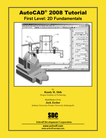
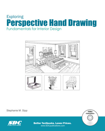
3-2ABAQUS for CATIA V5 TutorialsCopyrightedMaterialIntroduction:This tutorial is an extension of the problem described in chapter 2. The plate with acentral hole is pulled with a high load which drives the part into the plastic range. Thetrue stress/true strain curve is provided in tabular form for the plasticity model.Problem Statement:The steel plate shown below is subjected to a pressure load P at the two ends. Contrary tothe earlier model in chapter 2, the three planes of symmetry are used to reduce the finiteelement model as 2L/2H/2CopyrightedMaterialD/2
Elastic-plastic Analysis of a Notched PlateCopyrightedMaterial3-3CATIA Model:Create the CATIA model of the indicated plate with the following dimensions.L 0.15m, H 0.1m, W 0.02m, and D 0.025m.Use the Apply Material iconfrom the bottom row of toolbars. The use of this iconopens the material database box as shown next.CopyrightedMaterialChoose the Metal tab on the top; select Steel. Use your cursor to pick the part on thescreen at which time the OK and Apply Material buttons can be selected.Close the box. The material property is now reflected in the tree.CopyrightedMaterialCopyrightedMaterial
3-4ABAQUS for CATIA V5 TutorialsCopyrightedMaterialPoint the cursor to the Steel branch just created in the tree, right-click, and select theproperties from the contextual menu as shown.The Properties dialogue box shown below opens.CopyrightedMaterialSelect the Analysis tab from the list of tabs on the top of the dialogue box. The materialproperties supplied by the CATIA database appears. This data can be edited; however,the material data supplied directly to ABAQUS overrules the CATIA data. You will nextprovide the data directly through ABAQUS.CopyrightedMaterialSelect More at the bottom right corner. A second Properties dialogue box appearswhich is responsible for loading tabs associated with the installed workbenches.The box is shown below and may take a few seconds before it disappears.Note that additional tabs will appear in theProperties dialogue box.Use the scroll arrow to get access to theABAQUS Properties tab.CopyrightedMaterialscrollSelectABAQUS Properties
Elastic-plastic Analysis of a Notched Plate3-5A Warning box appears the first time that theABAQUS Properties are loaded. Ignore thewarning by pressing OK to close the box.CopyrightedMaterialThe initial (unfilled) window is shown below.CopyrightedMaterialOnce again, all the data supplied here overrules the data provided by the CATIAmaterials database. Select the Elasticity box. Since the material data in the presentproblem is independent of temperature, uncheck the box shown below. Finally, input theYoung’s modulus and the Poisson’s ratio. This will be the data that will appear in theABAQUS INPUT file. Press OK to close the Properties box.CopyrightedMaterialCheck ElasticityUncheck this boxCopyrightedMaterialInput Young’s ModulusInput Poisson’s Ratio
3-6ABAQUS for CATIA V5 TutorialsCopyrightedMaterialThe next several steps are new and were not required in chapter 2, which was primarilydealing with linear elastic analysis.Check the Plasticity boxand select the default Isotropic Hardening rule.Since the material data in the problem under consideration is assumed to be at a fixedtemperature, uncheck the appropriate box.You are now in the position to input the true stress/true strain data.Check PlasticityCopyrightedMaterialLeave defaultIsotropic HardeningUncheckTrue stress/True strainto be inputtedThe data shown below is for AISI 1020 hot-rolled steel. Note that the first entry in thetable corresponds to the yield strength at the plastic strain of zero.NOTE: In order to add a new line of data you have to press the e first line of the table must be theyield strength at zero plastic strain.
Elastic-plastic Analysis of a Notched Plate3-7CopyrightedMaterialRecall that the engineering stress/engineering strain data can be converted to the truestress/true strain data through the following formulas which are valid up to the neckingpoint.ε true ln(1 ε eng )σ true σ eng (1 ε eng )Upon the completion of the data entry, press the Applythe data in a different format. Close the box by pressingbutton which ck on the Save iconand save the part file in a directory of your choice. Here wehave created the directory AFC Tutorial chap3 storing all the files.CopyrightedMaterial
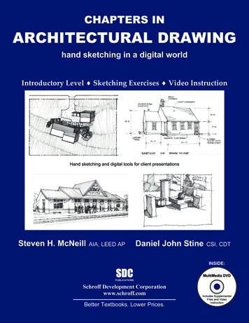
3-8ABAQUS for CATIA V5 TutorialsCopyrightedMaterialIf the part is still “gray”, one can change the rendering style. From the View toolbar, select the View modetoolbar.Next choose the Shading with Material iconThe part now appears shaded as shown ghtedMaterial
Elastic-plastic Analysis of a Notched PlateCopyrightedMaterialEntering the ABAQUS Structural Analysis Workbench:Select Start from the top menu, scroll down and select Analysis and Simulation,followed by ABAQUS Structural Analysis.CopyrightedMaterialYou will then find yourself in the new workbench with FEA icons and toolbars.The full interface with all toolbars in the default position is displayed below.CopyrightedMaterialCopyrightedMaterial3-9
3-10ABAQUS for CATIA V5 TutorialsCopyrightedMaterialClose the New Analysis Case by pressing OK.The representative element “Size” and “Sag” appears on your model. We have alsoshown the fully expanded tree for your information.CopyrightedMaterialRepresentative Element “Size” and “Sag”Click on the Save iconand save theAnalysis.1 file in a directory of yourchoice. Here we have created the directoryAFC Tutorial chap3 for storing all thefiles.CopyrightedMaterialIn order to change the size and sag, double-click on the branch OCTREE TetrahedronMesh.1. The data can be edited. Keep the default values and close the window.CopyrightedMaterial
Elastic-plastic Analysis of a Notched Plate3-11CopyrightedMaterialSelect the Mesh Visualization iconfrom the Model Manager toolbar. From the screen, select the block. The warning messagebelow appears that you can ignore by pressing OK.The finite element mesh appears on the screen.Note that the display of the mesh also gets recorded inthe tree by the addition of the Mesh.1 branch.CopyrightedMaterialBy selecting the Customize iconfrom the View mode toolbarCopyrightedMaterialyou can open the CustomView Modes dialogue box below and select different optionsfor display purposes. The above mesh was displayed bychecking the Dynamic hidden line removal option.An alternative way to display the mesh is to point the cursor tothe Nodes and Elements branch in the tree, right-click, andselect Mesh Visualization.CopyrightedMaterial
3-12ABAQUS for CATIA V5 TutorialsCopyrightedMaterialCreating an ABAQUS Step:The Analysis toolbar.has a sub-toolbar labeled Structur Select the General Static Step icon. The dialogue box shown below opens.Inspect the different options but keep the default entities. Since large plastic deformationis anticipated, check the Nonlinear geometry to be turned On.CopyrightedMaterialA Static Step-1 branch appears in the tree. Clearly this step belongs to s on OK to close the General Static Step dialogue box.CopyrightedMaterialApplying the Pressure Load:CATIA and ABAQUS for CATIA V5 (AFC) are geometrically based packages. Thismeans that the restraints and loads have to be applied on the geometrical entitiesassociated with the part. For example, these entities can be a vertex, an edge, a face, orthe entire body. One cannot apply restraints and loads on nodes or elements.The mesh that appears on the screen must therefore be replaced with the actual part.
Elastic-plastic Analysis of a Notched Plate3-13CopyrightedMaterialPoint the cursor to the branch of the tree labeled OCTREE Tetrahedron Mesh1, rightclick and select Activate/Deactivate. The part then appears on the screen.CopyrightedMaterialCopyrightedMaterialThe Prescribed Conditions toolbar. Select the Pressure Load iconLoadsThis action opens the Pressure dialogue box shown below.has a sub-toolbar called.Select the end face of the plate and enter -3E 8Pa for the Magnitude. The completedbox is displayed below.CopyrightedMaterial
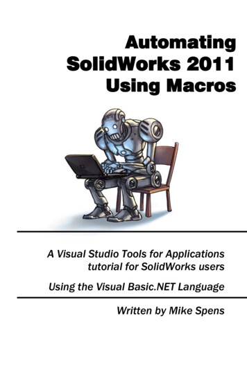
3-14ABAQUS for CATIA V5 TutorialsCopyrightedMaterialThe negative pressure indicates that the selected surfacein under a tensile load.The tree reflects the presence of the pressure loading.Applying the Restraints:CopyrightedMaterialThe Boundar toolbartoolbaris a sub-toolbar of the Prescribed Conditions.Select the Displacement Boundary Condition icon. In the resulting dialoguebox, select the face shown as Support. Assuming the xyz coordinate system is asindicated below, check the U2 box. If your part is oriented differently with respect to thexyx coordinate system, check the appropriate U1, U2, or U3 box. The displacementnormal to this face must be zero regardless.Select this face asthe supportCopyrightedMaterialzxCheck the U2 boxyCopyrightedMaterialOnce again, select the Displacement Boundary Condition icon.In the resulting dialogue box, select the face shown as Support. Assuming the xyzcoordinate system is as indicated below, check the U3 box. If your part is orienteddifferently with respect to the xyz coordinate system, check the appropriate U1, U2, orU3 box. The displacement normal to this face must be zero regardless.
Elastic-plastic Analysis of a Notched Select this face asthe supportCheck the U3 boxSelect the Displacement Boundary Condition icon. In the resulting dialoguebox, select the face shown as Support. Assuming the xyz coordinate system is asindicated below, check the U1 box. If your part is oriented differently with respect to thexyx coordinate system, check the appropriate U1, U2, or U3 box. The displacementnormal to this face must be zero regardless.Select this face asthe supportCopyrightedMaterialxyzCheck the U1 boxCopyrightedMaterialThe three prescribed displacements imposed appear in thehistory tree.Once again, it is emphasized that if your xyz orientation isdifferent from what is displayed, you have to check theappropriate U1, U2, and U3 boxes consistent with your xyzdirections.
3-16ABAQUS for CATIA V5 TutorialsCopyrightedMaterialRecall that the mesh was deactivated earlier to enable us to apply the loads and restraints.The little red markers on these two branches in fact confirm that they are deactivated.Deactivated earlierThis was achieved by pointing the cursor to the branch of the tree labeled OCTREETetrahedron Mesh1, right-clicking and selecting Activate/Deactivate.CopyrightedMaterialSelect the ABAQUS Consistency Checker iconfrom the Analysis Controltoolbar. You will note that the errors in the resulting dialogue boxare related to the mesh being deactivated.CopyrightedMaterialClose the Consistency Check box. To eliminate the errors listed, point the cursor tothe branch of the tree labeled OCTREE Tetrahedron Mesh1, right-click and selectActivate/Deactivate. The mesh then appears on the screen being superimposed on thepart as shown.CopyrightedMaterialNow activated
Elastic-plastic Analysis of a Notched Plate3-17CopyrightedMaterialOnce again select the ABAQUS Consistency Checker iconControl toolbardialogue box.from the Analysis. The previous errors no longer appear in theCopyrightedMaterialClose the Consistency Check box.CopyrightedMaterialCopyrightedMaterial
3-18ABAQUS for CATIA V5 TutorialsCopyrightedMaterialCreating an ABAQUS Job:Select the Create Job iconfrom the Analysis Control toolbar. The dialogue box shown below appears.Keep all the default settings. Note that the location of the Computation directory andthe Scratch directory can be set (changed) in this box.Close the Create Job box by pressing OK.CopyrightedMaterialA Job-1 branch is created in the tree.Submission Using the Job Manager:CopyrightedMaterialSelect the Job Manager iconin the Analysis Control toolbar. The Job Manager dialogue box appears on the screen.CopyrightedMaterial
Elastic-plastic Analysis of a Notched Plate3-19CopyrightedMaterialSelect the Write Inputbutton in the dialogue box. This results in anABAQUS input file being created. Also, it leads to the Write Input File window shownbelow.Close the window by pressing on Close.CopyrightedMaterialBefore the window closes, you will receive a messageconfirming the successful creation of the input file.Click on OK.CopyrightedMaterialSelect the Submitkey in the Job Manager window. The action results inthe Job Submission window displayed next.CopyrightedMaterialSelect the Continuebutton.
3-20ABAQUS for CATIA V5 TutorialsCopyrightedMaterialThe Status None in the Job Manager dialogue box changes to Status Run.Select the Monitorbutton.The Job Monitor window keeps updating the progress of the ABAQUS job.CopyrightedMaterialAs the run progresses, different steps are recorded in the Job Monitor window as shownbelow.CopyrightedMaterialThis particular job aborts after 27 iterations as displayed in the Job Monitor dialoguebox.CopyrightedMaterialRunningAborted
Elastic-plastic Analysis of a Notched Plate3-21CopyrightedMaterialIn order to view the reason behind the Abort status, you can select the Warnings andErrors tabs in the “big” Job Monitor window.Select theerror tabCopyrightedMaterialSelect theWarning tabCopyrightedMaterialIn this run, the reason for the Abort status is that, at the step 27, the number of iterationsto establish equilibrium has exceeded the default value set in ABAQUS.Close the Job Monitor window and select Attach Resultsin the JobManager dialogue box. Assuming that the run was successful and no errors weregenerated, the Attach Odb dialogue box below appears.CopyrightedMaterialClose the above window by pressing OK. Also close the Job Manager window.
3-22ABAQUS for CATIA V5 TutorialsCopyrightedMaterialNotice that the bottom of the tree records the creation of Job-1.odb file.Postprocessing:You are now in a position to conduct postprocessing.Point the cursor to the “Static Step-1”branch at the bottom of the tree, rightclick, and select Generate ABAQUSResults Image.CopyrightedMaterialYou are presented with the ABAQUSImage Generation dialogue boxwhere items to be plotted can beselected.CopyrightedMaterialThis action can also be achieved by selecting the Generate ABAQUS Results Imageiconfrom the Postprocessing toolbar.CopyrightedMaterial
Elastic-plastic Analysis of a Notched Plate3-23CopyrightedMaterialSelect the Translational displacement magnitude from the list and press OK. Thecontour plot at any particular increment can be requested by using the Select button.Contour at any particularincrement can be selctedCopyrightedMaterialIn the event that the deformed and undeformed meshes superimpose, point the cursor tothe OCTREE Tetrahedron Mesh.1, right click and select Hide/Show.The requested contour plot is displayed. The plot is also recorded in the tree.CopyrightedMaterialCopyrightedMaterialThe contour plot is drawn on the deformed shape which has been magnified for viewingpurposes. If you prefer the non-magnified scale, select the Amplification Magnitudeiconfrom the Analysis Tools toolbarIn the resulting dialogue box, set the Factor to 1.
3-24ABAQUS for CATIA V5 ect the Generate ABAQUS Results Image iconfrom the Postprocessing. From the ABAQUS Image Generation dialogue boxtoolbarselect Equivalent Plastic Strain.CopyrightedMaterialPoint the cursor to the branch of the tree labeled Equivalent Plastic Strain.1, rightclick, and select Activate/Deactivate. This will deactivate the contour and places thepart on the screen. Note that both contours plotted are deactivated now. This time activatethe first contour namely, Translational displacement magnitude.1.Obviously, every time a contour is plotted, by default the previous contour is d
Elastic-plastic Analysis of a Notched Plate3-25CopyrightedMaterialSelect the Cut Plane Analysis iconthe Analysis Tools toolbar.The part is cut with a plane and the contour entity (in this case Translationaldisplacement) can be viewed in the cut part. Note that the plane can be manipulated bythe compass; for example, it can be translated and rotated as desired. This feature isuseful to view the variable on interest inside of the part.CopyrightedMaterialCopyrightedMaterialYou may be interested in placing the two contours on the screen side-by-side. This isvery simple. First you have to make both contours active. This is achieved by placing thecursor on the two contour plots in the tree, right clicking, and selecting Activate/Deactivate.Make sure you activate both contoursCopyrightedMaterialContours and legends getsuperimposedWhen the two contours are activated, they get superimposed above each other. Thecontour legends are also superimposed as indicated above.
3-26ABAQUS for CATIA V5 TutorialsCopyrightedMaterialClick the Image Layout iconfrom the Analysis Tools toolbar.The Images Layout box, shown to the right, asksyou to specify the direction along which the two plotsare expected to be aligned.The outcome is side-by-side plots shown below.Contours side-by-sideCopyrightedMaterialLegends still superimposedCopyrightedMaterialAt this point, the contours are side-by-side but the legends are still superimposed. Toseparate then, select the legend with the left mouse button which in turn “dims” thecontour as shown below.CopyrightedMaterialLeft click on thelegend
Elastic-plastic Analysis of a Notched Plate3-27CopyrightedMaterialNow press the middle mouse button (and keep it pressed) and drag the mouse. In case ofa two mouse button, after the legend has been selected, click on the Pan iconPlace the selected legend at the desire location.Dragthe m the mousIs he iddle mo e whileuseld dobuttownnCopyrightedMaterialFinally, select either one of the two legends for the second time. This takes the actualcontour plots out of the “dim” mode.Select the legend again to take the contourout of the “dim” mode.CopyrightedMaterialCopyrightedMaterialOnce again, deactivate both contourplots. This places the part on thescreen.Both contours deactivated
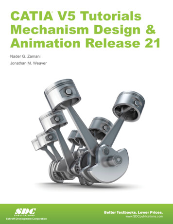
3-28ABAQUS for CATIA V5 TutorialsCopyrightedMaterialSelect the Surface Group iconfrom the Typed Groups toolbar. The resulting dialogue box allows you to select the desiredsurface.CopyrightedMaterialFor supports select this faceA surface group is recorded in the tree as shown.CopyrightedMaterialNow activate the Equivalent Plastic Strain.1 contour and double-click anywhere on thecontour.CopyrightedMaterialIf you are not getting the shaded mode, use the Shading with Material iconthe View Mode toolbar.from
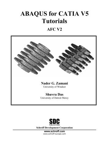
Elastic-plastic Analysis of a Notched PlateCopyrightedMaterial3-29Once you double-click on the contour, the Image Edition dialogue box below appears.CopyrightedMaterialPick the Selectionstab. Using the cursor, choose the Surface Group.1from the list and click on the button .CopyrightedMaterialThe final outcome is thecontour of the EquivalentPlastic Strain on the surfacegroup created.CopyrightedMaterial
3-30ABAQUS for CATIA V5 alCopyrightedMaterialCopyrightedMaterial
A Static Step-1 branch appears in the tree. Clearly this step belongs to ABAQUS-Analysis-Case-1. Press on OK to close the General Static Step dialogue box. Applying the Pressure Load: CATIA and ABAQUS for CATIA V5 (AFC) are geometrically based packages. This means that the restraints and loads have to be applied on the geometrical entities