Transcription
SolidWorks 2013Tutorial withVideo Instruction A Step-by-Step Project Based ApproachUtilizing 3D Solid ModelingVideoInstructionDavid C. Planchard CSWPMarie P. Planchard CSWPSDCP U B L I C AT I O N SSchroff Development CorporationBetter Textbooks. Lower Prices.www.SDCpublications.comAn audio/visualpresentation of thetutorial projects
Visit the following websites to learn more about this book:
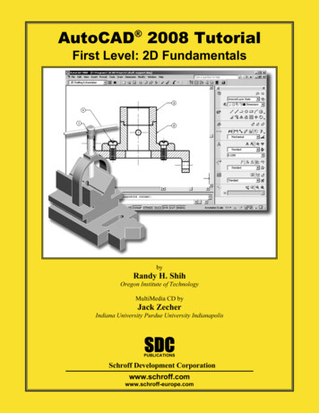
Chapter 1LINKAGE AssemblyLINKAGE AssemblyCourtesy ofSMC Corporation of AmericaBelow are the desired outcomes and usage competencies based on the completion ofChapter 1.Desired Outcomes:Usage Competencies: Understand the SolidWorks default UserInterface. Establish a SolidWorks session. Create 2D sketch profiles on the correctSketch plane.o FLATBAR Apply the following 3D features: ExtrudedBoss/Base, Extruded Cut and LinearPattern.Create an assembly: Understand the Assembly toolbar.o LINKAGE assembly Insert components into an assembly. Apply the following Standard mates:Concentric, Coincident and Parallel.Create three parts:o AXLEo SHAFT-COLLAR PAGE 1 - 1
LINKAGE AssemblySolidWorks 2013 TutorialNotes:PAGE 1 - 2
SolidWorks 2013 TutorialLINKAGE AssemblyChapter 1 - LINKAGE AssemblyChapter ObjectiveSolidWorks is a design software application used to model and create 2D and 3Dsketches, 3D parts, 3D assemblies and 2D drawings. The chapter objective is to provide acomprehensive understanding of the SolidWorks default User Interface andCommandManager: Menu bar toolbar, Menu bar menu, Drop-down menu, Contexttoolbar / menus, Fly-out FeatureManager, System feedback, Confirmation Corner,Heads-up View toolbar and an understanding of Document Properties.Obtain the working familiarity of the following SolidWorks sketch and feature tools:Line, Circle, Centerpoint Straight Slot, Smart Dimension, Extruded Boss/Base, ExtrudedCut and Linear Pattern.Create three individual parts: AXLE, SHAFT-COLLAR and FLATBAR.Create the assembly, LINKAGE using the three created parts and the downloadedsubassembly - AirCylinder from the DVD in the book.On the completion of this chapter, you will be able to: Start a SolidWorks session and navigate through the SolidWorks (UI) andCommandManager. Set units and dimensioning standards for a SolidWorks document. Generate a 2D sketch and identify the correct Sketch plane. Add and modify sketch dimensions. Create a 3D model. Understand and apply the following SolidWorks features:o Extruded Boss/Base, Extruded Cut and Linear Pattern Insert the following Geometric relations: Vertical, Horizontal, Coincident, MidPoint,Parallel and Equal. Download an assembly into SolidWorks and create an assembly. Understand the Assembly toolbar. Apply the following Standard mates: Coincident, Concentric and Parallel.PAGE 1 - 3
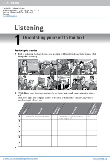
LINKAGE AssemblySolidWorks 2013 TutorialChapter OverviewSolidWorks is a 3D solid modeling CADsoftware package used to produce and modelparts, assemblies, and drawings.AXLESHAFTCOLLARSolidWorks provides design software to create3D models and 2D drawings.Create three parts in this chapter: AXLE SHAFT-COLLAR FLATBARFLATBARDownload the AirCylinder assemblyfrom the enclosed DVD.The AirCylinder assembly is alsoavailable from the internet.Combine the created parts and thedownloaded AirCylinder assembly tocreate the LINKAGE assembly.AirCylinder assemblyIllustrations in the book displaythe default SolidWorks user interfacefor 2013 SP0.Every license of SolidWorkscontains a copy of SolidWorksSustainabilityXpress. SolidWorksSustainabilityXpress calculates environmentalimpact on a model in four key areas: CarbonFootprint, Energy Consumption, AirAcidification and Water Eutrophication.Material and Manufacturing process region andTransportation Use region are use as inputvariables.PAGE 1 - 4LINKAGE assembly
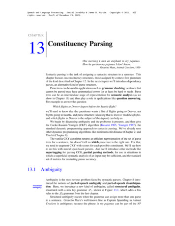
SolidWorks 2013 TutorialLINKAGE AssemblyAXLE PartThe AXLE is a cylindrical rod. The AXLEsupports the two FLATBAR parts.Tangent edges and origins are displayedfor educational purposes in this book.AXLEThe AXLE rotates about its axis. Thedimensions for the AXLE are determined fromother components in the LINKAGE assembly.FLATBARStart a new SolidWorks session. Create the AXLE part.AXLEApply the feature to create the part. Features are the buildingblocks that add or remove material.Utilize the Extruded Boss/Basetool from the Featurestoolbar to create a Boss-Exturde1 feature. The ExtrudedBoss/Base feature adds material. The Base feature (BossExtrude1) is the first feature of the part. The Base feature is thefoundation of the part. Keep the Base feature simple!The Base feature geometry for the AXLE is a simple extrusion.How do you create a solid Extruded Boss/Base feature for theAXLE? Select the Front Plane as the Sketch plane. Sketch a circular 2D profile on the Front Plane, centered atthe Origin as illustrated. Apply the Extruded Boss/Base Feature. Extend the profileperpendicular ( ) to the Front Plane.OriginUtilize symmetry. Extrude the sketch with the MidPlane End Condition in Direction 1. The ExtrudedBoss/Base feature is centered on both sides of the FrontPlane.Start a SolidWorks session. The SolidWorks applicationis located in the Programs folder.OriginPAGE 1 - 5
LINKAGE AssemblySolidWorks 2013 TutorialSolidWorks displays the Tip of the Day box. Read the Tip of the Day to obtain additionalknowledge on SolidWorks.from theCreate a new part. Select File, New from the Menu bar toolbar or click NewMenu bar menu. There are two options for new documents: Novice and Advanced. Selectthe Advanced option. Select the default Part document.Activity: Start a SolidWorks SessionStart a SolidWorks 2013 session.1)Click Start from the Windows Taskbar.2)Click All Programs3)Click the SolidWorks 2013 folder.4)Click the SolidWorks 2013 application. The SolidWorks program windowopens. Note: Do not open a document at this time.5)If you do not see thebelow screen, click theSolidWorks Resources.tab on the right sideof the Graphics windowlocation in the TaskPane as illustrated.6)Hover the mouse pointerover the SolidWorks iconas illustrated.7)Pin the Menu Bartoolbar. View youroptions.If available, doubleclick the SolidWorks 2013icon on the WindowsDesktop to start aSolidWorks session.The book is writtenusing Microsoft Office 2010on Windows 7 utilizingSolidWorks 2013 SP0.PAGE 1 - 6
SolidWorks 2013 TutorialLINKAGE AssemblyActivity: Understand the SolidWorks User Interface and CommandManagerMenu bar toolbarSolidWorks 2013 (UI) is design tomake maximum use of the Graphicswindow area. The default Menu bartoolbar contains a set of the mostfrequently used tool buttons from theStandard toolbar. The available tools are: New Open Save Print- Prints an active document Undo- Reverses the last action Select- Selects Sketch entities, components and more Rebuild- Rebuilds the active part, assembly or drawing File Properties- Shows the summary information onthe active document Options- Changes system options and Add-Ins forSolidWorks.- Creates a new document- Opens an existing document- Saves an active documentThe Search Knowledge Base and Community Forumoption from the Menu Bar toolbar requires Internet access.Menu bar menuClick SolidWorks in the Menu bartoolbar to display the Menu barmenu. SolidWorks provides aContext-sensitive menu structure.The menu titles remain the same forall three types of documents, but the menu items changedepending on which type of document is active.PAGE 1 - 7
LINKAGE AssemblySolidWorks 2013 TutorialExample: The Insert menu includes features in part documents, mates in assemblydocuments, and drawing views in drawing documents. The display of the menu is alsodependent on the workflow customization that you have selected. The default menu itemsfor an active document are: File, Edit, View, Insert, Tools, Window, Help, Pin.The Pinoption displays the Menu bar toolbar and the Menu bar menu asillustrated. Throughout the book, the Menu bar menuand the Menu bar toolbar is referredas the Menu bar.Until a file is converted to the current version ofSolidWorks and saved, a warning icon is displayed on theSave tool as illustrated.Drop-down menuSolidWorks takes advantage of the familiarMicrosoft Windows user interface. Communicatewith SolidWorks either through the; Drop-downmenu, Pop-up menu, Shortcut toolbar, Fly-out toolbaror the CommandManager.A command is an instruction that informs SolidWorksto perform a task. To close a SolidWorks drop-downmenu, press the Esc key. You can also click any otherpart of the SolidWorks Graphics window, or clickanother drop-down menu.Right-clickRight-click in the: Graphics window,FeatureManager, or Sketch to display a Contextsensitive toolbar. If you are in the middle of acommand, this toolbar displays a list of optionsspecifically related to that command.Press the s key to view/access previous commandtools in the Graphics window.PAGE 1 - 8
SolidWorks 2013 TutorialLINKAGE AssemblyConsolidated toolbarSimilar commands are grouped in the CommandManager.Example: Variations of the Rectangle sketch tool are grouped in asingle fly-out button as illustrated.If you select the Consolidated toolbar button without expanding: For some commands such as Sketch, the most commonlyused command is performed. This command is the first listed andthe command shown on the button. For commands such as rectangle, where you may want torepeatedly create the same variant of the rectangle, the last usedcommand is performed. This is the highlighted command whenthe Consolidated toolbar is expanded.System feedbackSolidWorks provides system feedback by attachinga symbol to the mouse pointer cursor. The systemfeedback symbol indicates what you are selecting orwhat the system is expecting you to select.FaceEdgeDimensionAs you move the mouse pointer acrossyour model, system feedback is provided toyou in the form of symbols, riding next tothe cursor arrow as illustrated.Confirmation CornerWhen numerous SolidWorks commands are active, a symbol or a set ofsymbols are displayed in the upper right hand corner of the Graphicswindow. This area is called the Confirmation Corner.When a sketch is active, the confirmation corner box displays two symbols.The first symbol is the sketch tool icon. The second symbol is a large red X.These two symbols supply a visual reminder that you are in an activesketch. Click the sketch symbol icon to exit the sketch and to saves anychanges that you made.When other commands are active, the confirmation corner box provides agreen check mark and a large red X. Use the green check mark to executethe current command. Use the large red X to cancel the command.PAGE 1 - 9Vertex
LINKAGE AssemblySolidWorks 2013 TutorialHeads-up View toolbarSolidWorks provides the user withnumerous view options from theStandard Views, View and Heads-upView toolbar.The Heads-up View toolbar is atransparent toolbar that is displayedin the Graphics window when adocument is active.For an activepart or assemblydocumentYou can hide, move or modify theHeads-up View toolbar. To modifythe Heads-up View toolbar: rightclick on a tool and select or deselectthe tools that you want to display.For an activedrawingdocumentThe following views are available:Note: The available views aredocument dependent. : Zooms theZoom to Fitmodel to fit the Graphics window. Zoom to Area: Zooms to theareas you select with a bounding box. Previous View Section View: Displays a cutaway of a part or assembly,using one or more cross section planes.: Displays the previous view.The Orientation dialog has a new option to display a viewcube (in-context View Selector) with a live model preview. Thishelps the user to understand how each standard view orientates themodel. With the view cube, you can access additional standardviews. The views are easy to understand and they can be accessedsimply by selecting a face on the cube.To activate the Orientation dialog box, press the spacebar orclick the View Orientationicon from the Heads up Viewtoolbar. The active model is displayed in the View Selector inan Isometric orientation (default view).As you hover over the buttons in the Orientation dialog box,the corresponding faces dynamical highlight in the ViewSelector. Select a view in the View Selector or click the viewfrom the Orientation dialog box. The Orientation dialog boxcloses and the model rotates to the selected view.PAGE 1 - 10
SolidWorks 2013 TutorialLINKAGE AssemblyClick the View Selector icon in theOrientation dialog box to show or hide the incontext View Selector.Press Ctrl spacebar to activate the ViewSelector.Press the spacebar to activate theOrientation dialog box. View Orientation box: Provides the abilityto select a view orientation or the number ofviewports. The available options are: Top,Left, Front, Right, Back, Bottom, Single view,Two view - Horizontal, Two view - Vertical,Four view. Click the drop-down arrowto access Axonometric views: Isometric,Dimetric and Trimetric. : Provides the ability toDisplay Styledisplay the style for the active view: Theavailable options are: Wireframe, HiddenLines Visible, Hidden Lines Removed,Shaded, Shaded With Edges. Hide/Show Items: Provides theability to select items to hide or show inthe Graphics window. The availableitems are document dependent. Note theView Center of Massicon. Edit Appearance : Provides the abilityto edit the appearance of entities of themodel. : Provides the ability toApply Sceneapply a scene to an active part orassembly document. View the availableoptions. View Setting : Provides the ability toselect the following settings: RealViewGraphics, Shadows In Shaded Mode,Ambient Occlusion and Perspective.PAGE 1 - 11
LINKAGE AssemblySolidWorks 2013 Tutorial Rotate view : Provides the ability to rotatea drawing view. Input Drawing view angleand select the ability to update and rotatecenter marks with view. : Provides the ability3D Drawing Viewto dynamically manipulate the drawing viewin 3D to make a selection.The default part and document settingdisplays the grid. To deactivate the grid, click Option
SolidWorks is a design software application used to model and create 2D and 3D sketches, 3D parts, 3D assemblies and 2D drawings. The chapter objective is to provide a comprehensive understanding of the SolidWorks default User Interface and CommandManager: Menu bar