Transcription
CHAPTERS INARCHITECTURAL DRAWINGhand sketching in a digital worldIntroductory Level Sketching Exercises Video InstructionHand sketching and digital tools for client presentationsSteven H. McNeillAIA, LEED APDaniel John StineCSI, CDTINSIDE:SDCMultiMedia DVDPUBLICATIONSSchroff Development Corporationwww.schroff.comBetter Textbooks. Lower Prices.Includes SupplementalFiles and VideoInstruction
C H A P T E R SI NA R C H I T E C T U R A LD R A W I N GChapter8The Perspective: Two-Point IAt this point you should have a comfort level with your pensufficient to begin exploring the fundamentals of the perspectivedrawing. This is an exciting step in learning to draw because youcan see the drawings begin to “come to life”!Aperspetive drawing is a two-dimensional drawing which represents athree-dimensional object or scene and takes into account the phenomenonthat things appear to get smaller the further they are from the viewer.There’s a bit more to it than that (which you will cover in this chapter), but this isa working definition we will start with. Additionally, a perspective drawing looksvery much like what we perceive when looking at the world.Below are the three primary types of perspective created by ArchitecturalDesigners: [from left to right] one-point, two-point and three-point perspectives.Vertical and Horizontal line work:Notice how the one-point perspective has bothhorizontal and vertical lines, the two-point onlyhas vertical lines and the three-point has neither.8-1
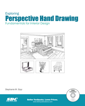
C H A P T E R SI NA R C H I T E C T U R A LD R A W I N GThe Horizon LineOne of the first things you need to understand when it comes to perspectivedrawing is the Horizon Line – what it is and how it relates to the drawing. In thesimplest of terms, the Horizon Line is the edge of the earth; at least the edge as it isperceived from the eye. As the earth curves away from any one person’s view,they see a distinct line between the earth and the sky. Even though the earth isround, it is so large that it appears to be flat. When drawing a perspective drawingthis important reference line is assumed to be flat (i.e., horizontal).In most perspectives, renderings and photographs you don’t usually see theHorizon Line because it is obscured by trees, hills, buildings, etc. However, thereare some cases in which you do see it, such as when you have the ocean or a vastfield as a backdrop to your building.The photo below helps to understand the Horizon Line by providing a real-worldexample. This example is of a building pictured with a large body of water behindit (this is not an ocean, but it is the largest freshwater lake in the world – bysurface area – Lake Superior). Notice the Horizon Line labeled in the picture.HorizonLineUnderstanding the Horizon Line8-2
T H EP E R S P E C T I V E :T W O - P O I N TIAnother quick example of the Horizon Line is shown in the photo below. A simplepicnic bench is not much different than a building when it comes to perspective;it has four sides and a top.You should pay close attention to the sketched overlays on this page and theprevious one. These overlays should make clear the close relationship between ahand drawn perspective (which you will learn how to do in this chapter) and aphotograph (or, better, what you see with your eyes)!HorizonLineUnderstanding the Horizon LineThe Vanishing Point is not something visible as is the Horizon Line. However itis possible to locate the Vanishing Points by extending lines back until theyconverge (as shown above). The lines will always converge on the Horizon Lineand thus reveal the Vanishing Point for the object under consideration.8-3
C H A P T E R SI NA R C H I T E C T U R A LD R A W I N GThe Two-Point PerspectiveTwo-point perspective drawings are two-dimensional drawings that representthree-dimensional objects or scenes. As the name implies, there are two points,referred to as Vanishing Points – VP. These points establish the perspective lineswhich are both relative to a Horizon Line (HL). The object being depicted hasthree primary types of lines: Perspective lines, which always converge at the Vanishing Points. Vertical lines, which are always truly vertical to the page. Angled lines, which are usually drawn by ‘connecting-the-dots’ via line workfully developed from the previous two line types.Two-point perspective drawings are primarily meant for rectilinear objects. Forexample, a uniform series of blocks can be sketched much easier than an ‘organic’shaped suburban development.The concepts covered can be applied to more detailed embellishments such aswindows and siding, sidewalks and driveways, fences and garages.In the image above you should take a moment to notice a few things:1) All lines are either vanishing or perfectly vertical.2) Anything drawn outside of an imaginary circle (actually shown on the nextpage) is too distorted and should be avoided.3) Objects completely below the horizon are as viewed from the top (aerialview, like from an airplane), and objects completely above are as viewedfrom below (worm’s eye view). You can quickly create rectilinear objectsin any shape or size by sketching the vanishing lines and vertical lines asshown!8-4
T H EP E R S P E C T I V E :T W O - P O I N TITwo-Point PerspectiveThe following exercise will walk you through the steps required to develop a twopoint perspective of the exterior of a residence. You are encouraged to followingalong on a separate piece ofpaper or in a sketch book.The exact dimensions andproportions do not reallymatter at this time as youare focusing on themechanics of perspectivedrawings. Try drawing thisfreehand first and then tryagain using a straightedge.The bulleted steps on the next page relate to the ‘lettered’ and then ‘numbered’sketches on the opposite page:8-5
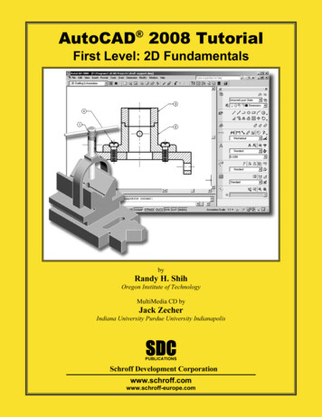
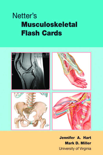
C H A P T E R SI NA R C H I T E C T U R A LD R A W I N GMain building with gable roof – Image AThis first step is simply sketching a basic box with a gable roof element dropped ontop. You should try to make your sketch as similar as possible in terms ofproportions – the vertical centerline (centered between the two Vanishing Points) hasbeen added to aid in this.1. Draw a vertical line just to the right of the ‘centerline’ with equal portionsabove and below the Horizon Line (see one vertical line marked with a #1).2. Connect-the-dots: draw four lines from the VP’s to the top and bottom ofthe vertical line as shown (see four lines marked with a #2).3. Draw two vertical lines to define the overall size of the main building.4. Draw an ‘X’ and a vertical line at its intersection to discern the midpoint ofthe gable end of the building. (Note: It is not the midpoint of the bottomedge of the building – confirm this with a scale).5. Draw the ridge line of the roof: a line from VP-1 to the vertical line sketchedin the previous step. (The location of this line determines the pitch of theroof; higher steeper.)6. Connect-the-dots: draw lines to create the gable roof edges.7. Lightly sketch the hidden portions of the building as shown.Bisecting the building – Image BHere you will learn how to find the exact middle of the building, this will help inlocating the cross-gable in the next image/task.1. Sketch an ‘X’ on the bottom plane of the building.2. Draw a perspective line from VP.2 which passes through the ‘X’.3. Sketch three vertical lines as shown (the vanishing line just drawn helpedestablish the starting point on the front and back face of the building).4. Connect-the-dots: from the intersection of the roof and three vertical lines.FYI: The two visible bisecting lines have an arrow at the top and bottom in thisimage and the next one to make them stand out – these lines will eventually beerased.Adding cross-gable entry – Image CNext you will sketch in the “bump out” on the front of the building.1. This perspective line (from VP.1) determines how far “out” the “bump” willbe.2. Draw two vertical lines a certain distance apart and approximately centeredon the main building (you will learn to be more precise later).3. Draw two perspective lines (from VP.2) to establish the bottom edges.4. Draw a vertical line up to the roof edge – from the intersection of theperspective line just drawn and the bottom front edge of the main building.5. Do the same as step three to establish the top edges (from VP.2)6. Draw this perspective line (from VP.1) to verify the top-front edge is correct.7. Use the ‘X’ method to discern the center of the gable wall.8. Sketch the ridge line of the entry roof – the location determines roof slope.9. Connect-the-dots: the remaining valley lines can be easily drawn.All lines should be sketched very lightly with pencil and the visible lines can be madedarker at the end, as well as erasing the unneeded reference lines and hidden lines.8-6
T H EP E R S P E C T I V E :T W O - P O I N T54223322133321852641378-7I
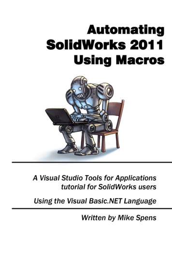
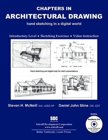
C H A P T E R SI NA R C H I T E C T U R A LD R A W I N GCentered and symmetrical addition – Image DThe following steps show you how to make an extrusion off the main building whichis symmetrical. You cannot measure in from each side an equal distance becausethings get closer together as you approach the Vanishing Points.1. The first line (from VP.2) will determine how large the extrusion (or addition)will be from the main mass of the residence.2. Here you will basically extend the front and back bottom (i.e., grade) line outto the previous line drawn. (Sketch lightly as these lines will be erased.)3. Draw an ‘X’ in the large, flat, rectangle just created.4. Now you will draw a vanishing line (from VP.2) near the building. Theintersection of this line and the ‘X’ lines will establish the front and back walllocations for the addition (which will be drawn in the next step).5. Draw two lines (from VP.1) so that they pass through the intersection of the‘X’ (from step 3) and the perspective line (from step 4), and terminate theselines at the perspective line drawn in step 1) – as shown in image D.Completing the massing of the addition – Image ENow that the footprint of the addition is sufficiently developed you can create theremaining line work.1. Draw four vertical lines as shown.2. Draw a perspective line (if needed – i.e., if you erased the previous one youdrew) – from VP.2 to the roof edge of the main building. This assumes theroof edge of the addition will align with the main building and not be lower(simply swinging this perspective line down a bit would allow for thischange).3. Draw two vanishing lines (from VP.1) through the line drawn in the previousstep and the vertical lines at the main building (drawn in step 1).4. Finding the middle of the gable end of the main building, you can sketch theroof slope lines. This is done in conjunction with the next step which locatesthe ridge line.5. Draw the ridge line (from VP.1).6. Find the middle of the gable end of the addition and finish sketching thesloped roof edges.At this point you have developed the main masses of your structure. Now you canerase the reference lines and hidden lines, and then darken the remaining lines.Another option is to use tracing paper and a soft pencil to sketch a new image basedon the ‘visible’ lines of your original sketch.Again, you may use these techniques toadd windows, siding, trim, chimneysand such. Here is another good use fortracing paper: you can sketch differentwindow and siding options on thetracing paper, so you don’t need to startfrom scratch with the base model everytime!8-8
T H EP E R S P E C T I V E :T W O - P O I N T4521253452361If you really want todevelop your sketchingskills, you should try todraw some nonarchitectural objects. Thiswill help you create morelively architecturalrenderings!8-9I
C H A P T E R SI NA R C H I T E C T U R A LD R A W I N GThe Human Scale MethodOne challenge we often have when sketching in perspective is making all thevarious parts at the proper scale. This gets easier with practice and experience, butuntil then you need to be able to use a few tricks to establish scale or even todouble check parts of your previously drawn perspective. In this section you willlearn about a technique called the Human Scale Method, which uses a 6 foottall measuring stick (i.e., a person) to size up objects in the perspective.When sketching a building, a designermay get the overall building correct,but then they may make the windowstoo small or the door too large; thishas a negative impact on the perceivedaesthetics of the design. The HumanScale Method projects the height of aperson around the scene to compareand verify vertical heights. Forexample, if you project the six footperson’s height onto the face of yourbuilding and the second floor windows are not approximately “another person”in height above (i.e., 12 feet total) something is probably wrong.In the following tutorial you will learn how to create a simple rectangular buildingwith a gable roof using the Human Scale Method.Step A – the horizon, a vanishing point, and a personBefore you begin drawing, you should remember you are not creatingpresentation drawings, so remember to work fast, keep it loose and don’t getbogged down! The example drawings in this section have been drawn with astraight edge just to make things very clear to you, but it is still all hand drawn.Start out by drawing a horizontal line; this is the horizon. Next, you will sketch agesture type person (covered in Chapter 2) with the head on the horizon (you willlearn more about this later in the Entourage section). The size of the person willdictate the overall size of the sketch so try to make it just the right size, which willallow the building to mostly fill the page - not so large it will not fit on the paperor too small that it is hard to show the proper level of detail; the only “right”answer is that this comes with experience.The next fundamental step to set up your perspective is to locate the VanishingPoints (VP) so you can begin projecting lines. Where do you put the VanishingPoints? If you are close to the object, the Vanishing Points are further apart, and ifyou are further away the VP’s are closer together.8-10
T H EP E R S P E C T I V E :T W O - P O I N TIThe example directly below shows one Vanishing Point on the left, the Horizon Lineand a person who we will assume is 6′-0″ tall. The other Vanishing Point will beadded later.Just so you know, even though the horizon actually curves with the surface of theearth, we always draw a horizontal line as the curve is not perceived by the eye.Also, this view would be from another person’s perspective – which is why thehead is on the horizon. If the view was from an airplane, the head would be wellbelow the Horizon Line (if the HL showed up at all).Step B – project the person back to one vanishing pointNow that you have the Horizon Line, a Vanishing Point and a person sketched, youcan project a set of lines from the feet and head of your person back to one of theVanishing Points. Obviously the person’s feet are on the ground, so the line fromthe feet to the Vanishing Point is also on the ground. From this “grounded” lineyou can project lines up to start your building. In this example the head is on theHorizon Line so you do not really need to project any lines from the head.8-11
C H A P T E R SI NA R C H I T E C T U R A LD R A W I N GStep C – determine the required heightUsing the approximate size of your human measuring stick, you can easily sketchadditional vanishing lines to establish various heights. Remember, the height staysconstant along a vertical line; notice the various 6′-0″ tall lines in the image below.For example, imagine the gesture person below with another person standing onhis shoulders. This second person’s head would (or should) align with the nextvanishing line above.In the next section, after the Human Scale Method, you will study how to dividefaces and spaces into smaller segments; which will allow more accuracy in yoursketch.Step D – describing a surfaceNow you can draw vertical lines, using the Vanishing Lines for reference. Oncethese vertical lines hit the other Vanishing Line (i.e., off the persons head, which ison the HL), you have made a six foot tall line. On one vertical line the scale doesnot change (like it does in plan) so you can use that 6 foot measure to establishthe height of the building (e.g., 2 units 12′ or 3 units 18′).As you can see in the image on the next page, a surface is described by drawingtwo vertical lines and then “connecting the dots” along the vanishing lines.In a similar fashion, you can establish another Vanishing Point and develop theadjacent surface.8-12
T H EP E R S P E C T I V E :T W O - P O I N TStep E – additional six foot squaresUsing the method shown graphically below, you can add additional 6′ x 6′surfaces (additional information is provided on Dividing Spaces in the nextsection). Notice this works in perspective as well as in flat two dimensionaldrawings (the sketch in the lower left is such a flat drawing).8-13I
C H A P T E R SI NA R C H I T E C T U R A LD R A W I N GStep F – gable roof edgeOnce you have your primary box established you are now in a position to developthe gable roof edge. As shown (and numbered) below, you can draw an “X” onthe surface from corner to corner. Now draw a vertical line which passes throughthe intersection of the two diagonal lines. Finally you draw the diagonal lines thatform the edge of the gable roof.Step G – dividing a surface into odd numbersIf you already have the overall surface described and you want to add an oddnumber of vertical lines, then do this:1. Divide the vertical line into the number of spaces desired. As you shouldrecall, the length is consistent along the length of the vertical lines in atwo-point perspective. Therefore you can use a scale if you want to bevery accurate or you may eyeball it seeing as things are not distorted. Inany case, make a small tick on the vertical lines for reference.2. Draw lines from the tick marks, made in the previous step, back to theVanishing Point. In the image on the top of the next page there are twoticks, with two corresponding lines extending to the Vanishing Point. Theselines should be very light on your drawing as they are only for reference.3. Draw a diagonal line across the surface under consideration. This shouldalso be a rather light line which is only for reference.4. Sketch vertical lines wherever a vanishing line (drawn in step 2) intersectsthe diagonal line (drawn in step 3).8-14
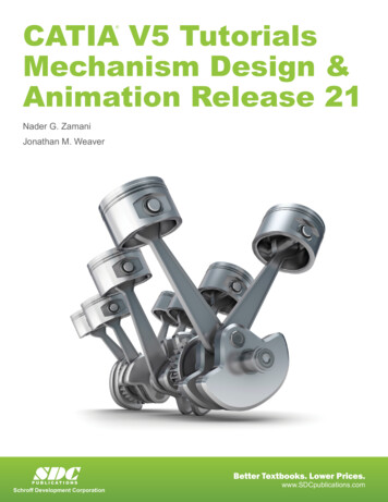
T H EP E R S P E C T I V E :T W O - P O I N TIStep H – completing the gable roofFinishing the roof consists, mostly, of connecting the dots. First you sketch a linefrom the peak of the gable roof (drawn in step F) back to the Vanishing Point. Thelast edge to be defined (the back edge in this example – below) is almost parallelto the front edge; this line is usually approximated.Once you have the Human Scale defined on one surface you can project it aroundthe corner and onto other surfaces. To do this you simply project a line from theintersection of the previously draw lines back to the other Vanishing Point.8-15
C H A P T E R SI NA R C H I T E C T U R A LD R A W I N GFinally, you may firm up the major lines. Use a rolling parallel rule to add verticalsiding (as shown below) and roofing if the perspective is not too sharp (otherwisethe lines are not parallel).We will cover a little more on this after the next section on Dividing Spaces.The end result is an accurately scaled two-point perspective drawing. You will bepresented with several exercises on this method to help drive the concept home!Study Sketches by Darryl Booker,Associate Professor, North Dakota State University8-16
–T H EP E R S P E C T I V E :N A M ET W O - P O I N TID A T EExercise 8-1Discover the Horizon Line / Create Boxes from RectanglesThe first task in this exercise is to discover the Horizon Line. This is done byprojecting vanishing lines back towards the vanishing point; where the linesconverge is where the vanishing point is. You will need to tear this page out andtape it onto a larger piece of paper as the Vanishing Points will not fit on thispage. The second task is to turn these surfaces into three-dimensional objects –you decide the depth to show.E8-1EXERCISES8Chapter 8C H A P T E R
8–T H EP E R S P E C T I V E :N A M ET W O - P O I N TID A T EExercise 8-2Chapter 8Storyboard Exercise – DataMake a few copies of this page and try sketching some rectangular shapes similarto those shown at the beginning of Chapter 8. Try to create your own variationson this theme.EXERCISESC H A P T E RE8-2
–T H EP E R S P E C T I V E :N A M ET W O - P O I N TID A T EExercise 8-3Human Measuring StickCompose a small 12′ by 18′ building, witha sidewall 9′ high and a gable roof. Theheight to the ridge of the gable is 12′.Again, use the human measuring stickmethod (i.e., a six foot person) toapproximate dimensions as well as thediagonal method to construct the gableroof. Use the vertical lines as one corner ofthe building.E8-3EXERCISES8Chapter 8C H A P T E R
–T H EP E R S P E C T I V E :N A M ET W O - P O I N TID A T EExercise 8-4Human Measuring StickUsing the same background as in theprevious exercise, create a composition ofstacked 6 feet by 6 feet by 6 feet cubes.Make any arrangement you wish, but usethe diagonal methods described earlier tocreate accuracy; create at least 7 cubes. Puta gable roof on one or more of the topcubes. Use the vertical line as one cornerof the building.E8-4EXERCISES8Chapter 8C H A P T E R
–T H EP E R S P E C T I V E :T W O - P O I N TN A M ED A T EExercise 8-5Human Measuring StickUsing the human figure as a 6 foot measuringstick, construct a two-point perspective of ablock 18′ high, 12′ wide and 18′ deep with a 9′high (and 3′ wide) door in one wall. Use thediagonal method to accurately repeat the humanmeasuring stick modules. Use the vertical lineprovided as one corner.E8-5IEXERCISES8Chapter 8C H A P T E R
–T H EP E R S P E C T I V E :N A M ET W O - P O I N TID A T ESelf-Exam:The following questions can be used as a way to check your knowledge of thislesson. The answers can be found at the lower left on this page.1.It is not possible to find the Vanishing Points in a printed photograph.(T/F)2.The three types of perspectives are: 1-, 2- and 3-point. (T/F)3.It is not possible to sketch equal spaces which step back into theperspective view. (T/F)4.In a 2-point perspective, all lines are either vanishing or.5.-point perspectives have both horizontal and vertical lines.Review Questions:Self-Exam Answers:1 - F, 2 - T, 3 - F, 4 - Vertical, 5 – OneThe following questions may be assigned by your instructor as a way to assess yourknowledge of this section. Your instructor has the answers to the review questions.1.All lines converge in 3-point perspectives. (T/F)2.In the Human Scale method, the [human’s] head is aligned with theHorizon Line for eye-level drawings. (T/F)3.Rectangular shapes are sketched more easily than are organic shapeswith the 2-point perspective method. (T/F)4.In a photograph, one does not usually see the horizon line. (T/F)5.In a 2-point perspective, the two vanishing points are not always on theHorizon Line. (T/F)6.The main value in the method ismaking the various parts of the drawing the proper size.7.Sketching an “X” on a surface in perspective locates the center. (T/F)8.3-point perspectives have vertical line work in them. (T/F)9.It is possible to reveal the Horizon Line in a photograph. (T/F)10. In a 2-point perspective, the length is consistent along any given verticalline. (T/F)Q8Questions8CHAPTER 8C H A P T E R
CHAPTERS IN ARCHITECTURAL DRAWING 8-2 The Horizon Line One of the first things you need to understand when it comes to perspective drawing is the Horizon Line – what it is and how it relates to the drawing. In the simplest of terms, the Horizon Line is the edge of the