Transcription
SIMULATION OF A SERIES RESONANT CIRCUITECE562: Power Electronics ICOLORADO STATE UNIVERSITYModified in Fall 2011ECE 562 Series Resonant Circuit (NL5 Simulation)Page 1
PURPOSE: The purpose of this lab is to simulate the series resonant circuit usingMATLAB and NL5 to better familiarize the student with some of its operatingcharacteristics. This lab will explore some of the following aspects of the series resonantcircuit: Input impedance Magnitude and phase margin Zero frequency Output power Output current Plot the natural response for the output voltage Zero poles Phase of transfer function Input impedance for varying resistance (R)NOTE: The simulations that follow are intended to be completed with NL5. It isassumed that the student has a fundamental understanding of the operation of NL5.Build the schematic shown in Figure A. Vm is an AC voltage source. Set the type to ‘Sin,’ and the magnitude to 1 volt.L1 is an ideal inductor. Set to 1000µH.R is an ideal resistor. Set to 200 Ω.C1 is an ideal capacitor. Set to 40pF.Figure A – Initial schematic.ECE 562 Series Resonant Circuit (NL5 Simulation)Page 2
Under the ‘AC Settings’ tab, specify V1 as the source, a frequency range of 100 Hz to10 MHz, 1000 points, and a logarithmic scale.Add a trace for the input impedance by selecting AC / Data / Traces from the menu.Click on ‘Function’ in the ‘Add new trace’ section. Add the function V(V1)/I(V1).ECE 562 Series Resonant Circuit (NL5 Simulation)Page 3
Run the simulation by selecting ‘AC’ and then ‘Start’ from the drop down menus.Figure B – Magnitude and phase of the input impedance.Referring to Figure B, what is the input impedance value of RLC circuit?Next, we want to measure the total inductor current of RLC series resonance circuit.Right click on the inductor, and select Add trace / current. Re-run the simulation andadjust the display to show the data of interest.Figure C – Inductor current.What is the value of the inductor current? Describe the phase characteristics of theinductor current.ECE 562 Series Resonant Circuit (NL5 Simulation)Page 4
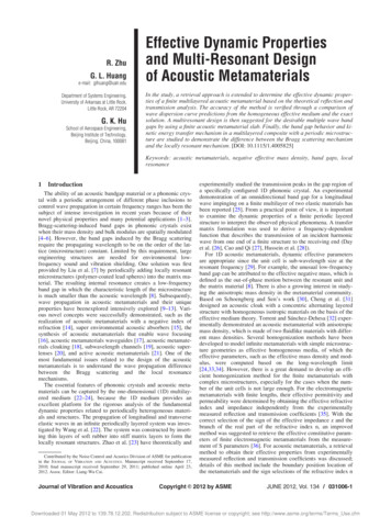
Next, we want to simulate the input impedance of series RLC resonant circuit with avarying resistor. Use the same circuit as above, but change the resistor values to 50,100, 200, 400, 2000, 4000, and 8000 Ω. This type of parametric sweep isaccomplished in NL5 with a script. Go to Tools / Script and click on the Sweep tab.Select List instead of Loop. Enter R1 as the Name, enter the parametric values in thebox, and select AC sweep. Click on the blue arrow to start the script.What is the input impedance value of RLC circuit with varying resistances?Figure D – Input impedance values of the RLC circuit.ECE 562 Series Resonant Circuit (NL5 Simulation)Page 5
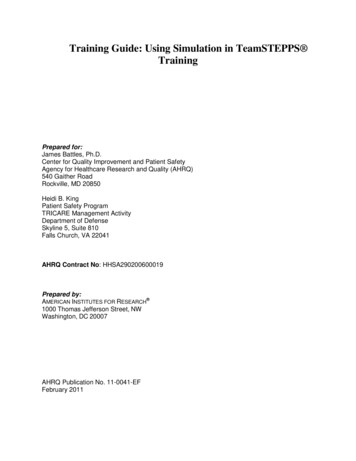
Next, we want to simulate the inductor current of series RLC resonant circuit withvarying resistance values.Figure E – Inductor current for varying resistor values.What is the value of the inductor current? Describe the phase characteristics of theinductor current.Next, simulate the output voltage as a function of varying resistance. For this example,take the voltage across the capacitor as the output voltage.ECE 562 Series Resonant Circuit (NL5 Simulation)Page 6
Figure F – Output voltage for varying resistor values.What is the value of the output voltage? Describe the phase characteristics of theoutput voltage.ECE 562 Series Resonant Circuit (NL5 Simulation)Page 7
For Homework:You need to re-solve the parallel resonant circuit with Capacitor ESR and see itseffects on the magnitude and phase plots in some detail. For example choosethe ratio of the C ESR to the load resistance to be in the ratio range from 0.01 to1.Series Resonant Circuit Using MATLABNOTE: The simulations that follow are intended to be completed with MATLAB .It is assumed that the student has a fundamental understanding of the operationof MATLAB . MATLAB provides tutorials for users that are not experienced withits functions.In this lab you will learn how to write a function to varying, calculating and plottingthe input impedance, current and output voltage of the series RLC resonant tankcircuit. You can define your own function in MATLAB. A function must start witha line.Function return-value function-name (arguments)So that MATLAB will recognize it as a function. Each function must have its ownfile and the file must have the same as the function.PROCEDURE:Part 1: Write a function to calculate the total input impedance of series RLCresonant circuit as shown in Figure 1.Vm is a variable voltage. Set to 1 voltsL is a variable inductor. Set to 1000µH.R is a variable ideal resistor. Set to 200Ω.C is a variable ideal capacitor. Set to 40pF.Page 8 of 33
Page 9 of 33
Figure 1: The input impedance of series RLC tank circuit.Once the above m file is captured, the simulations can be run. First, go to yourdirectory. Find your m file and then run your file. If there is a red message onPage 10 of 33
your MATLAB window, then you need to correct your error. Otherwise, you willsee the solution as show in figure 2.Page 11 of 33
Figure2: The output of input impedance of series RLC tank circuit.Next, plot the total input of the series resonant RLC tank circuit. Write anotherfunction to calculate the total input current of series RLC tank circuit as shown inFigure 3. All the initial variables and values are remained the same.Vm is a variable voltage. Set to 1 voltsL is a variable inductor. Set to 1000µH.R is a variable ideal resistor. Set to 200Ω.C is a variable ideal capacitor. Set to 40pFPage 12 of 33
Figure 3: the function to calculate the total input current of series RLC tank circuitOnce the above function file is captured, the simulations can be run. First, go toyour directory. Find your function file and then run your file. If there is a redmessage on your MATLAB window, then you need to correct your error.Otherwise, you will see the solution as show in figure 4.Page 13 of 33
Page 14 of 33
Figure 4: the output and plot of the total input current of series RLC tank circuitNow write a function to varying R of the input impedance of series RLC resonantcircuit by adding an array of Resistors (R) value. Again all the initial variablesand values are remain the same.Vm is a variable voltage. Set to 1 voltsL is a variable inductor. Set to 1000µH.R is a variable ideal resistor. Set to 200Ω.Page 15 of 33
C is a variable ideal capacitor. Set to 40pFWrite a loop function to do the varying resistors value, calculate and plot theoutput of total input impedance of series RLC resonant circuit. When thefunction to varying R of the input impedance of series RLC resonant circuitfunction file is captured, the simulations can be run. If there is any errormessage on your MATLAB windows, then correct your error and then rerun thesimulation. Otherwise, you will see the result as show belowPage 16 of 33
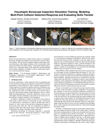
Figure 5: A function of the input impedance of series RLC resonant circuit withvarying ResistorPage 17 of 33
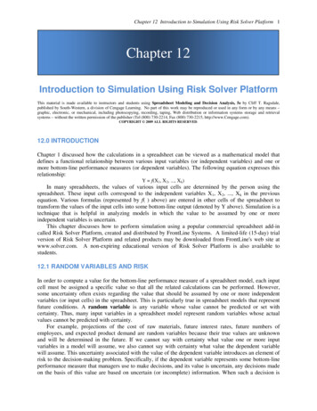
Figure 6: Output of the input impedance of series RLC resonant circuit withvarying ResistorNow write a function to varying R of the input current of series RLC resonantcircuit by adding an array of Resistors (R) value. Again all the initial variablesand values are remain the same.Vm is a variable voltage. Set to 1 voltsL is a variable inductor. Set to 1000µH.R is a variable ideal resistor. Set to 200Ω.C is a variable ideal capacitor. Set to 40pFWrite a loop function to do the varying resistors value, calculate and plot theoutput of total input current of series RLC resonant circuit. When the function tovarying R of the input current of series RLC resonant circuit function file iscaptured, the simulations can be run. If there is any error message on yourMATLAB windows, then correct your error and then rerun the simulation.Otherwise, you will see the result as show belowPage 18 of 33
Figure 7: A function of the input current of series RLC resonant circuit withvarying ResistorPage 19 of 33
Page 20 of 33
Figure 8: Output of the input current of series RLC resonant circuit with varyingResistorPage 21 of 33
Now write a function to varying R of the output voltage of series RLC resonantcircuit by adding an array of Resistors (R) value. Again all the initial variablesand values are remain the same.Vm is a variable voltage. Set to 1 voltsL is a variable inductor. Set to 1000µH.R is a variable ideal resistor. Set to 200Ω.C is a variable ideal capacitor. Set to 40pFWrite a loop function to do the varying resistors value, calculate and plot theoutput voltage of series RLC resonant circuit. When the function to varying R ofthe input current of series RLC resonant circuit function file is captured, thesimulations can be run. If there is any error message on your MATLAB windows,then correct your error and then rerun the simulation. Otherwise, you will see theresult as show belowPage 22 of 33
Figure 9: A function of the output voltage of series RLC resonant circuit withvarying ResistorPage 23 of 33
Figure 10: This figure is shown the output voltage of series RLC resonant circuitwith varying ResistorPage 24 of 33
For Homework:You need to re-solve the parallel resonant circuit with Capacitor ESR and see itseffects on the magnitude and phase plots in some detail. For example choosethe ratio of the C ESR to the load resistance to be in the ratio range from 0.01 to1.Now write m file to varying R of the natural response of current in series RLCresonant circuit by adding an array of Resistors (R) value. Again all the initialvariables are remain the same but change their values.Vm is a variable voltage. Set to 0 voltsL is a variable inductor. Set to 5mH.R is a variable ideal resistor. Set to 8Ω.C is a variable ideal capacitor. Set to 200µFIo is a variable ideal of inductor current. Set to 2 amps.Vo is a variable ideal of capacitor voltage. Set to -5 volts.Write a loop function to do the varying resistors value, calculate and plot thenatural response of current for series RLC resonant circuit. When the function tovarying R of the natural response of current in series RLC resonant circuit file iscaptured, the simulations can be run. If there is any error message on yourMATLAB windows, then correct your error and then rerun the simulation.Otherwise, you will see the result as show belowPage 25 of 33
Page 26 of 33
Figure 11: the m file to calculate and plot the natural response of current in seriesRLC resonant circuit with varying ResistorPage 27 of 33
Figure 12: This figure is shown the output of the natural responses of current inseries RLC resonant circuit with varying ResistorNow write m file to varying R of the natural response of capacitor voltage in aseries RLC resonant circuit by adding an array of Resistors (R) value. Again allthe initial variables are remain the same but change their values.Vm is a variable voltage. Set to 0 voltsL is a variable inductor. Set to 5mH.R is a variable ideal resistor. Set to 8Ω.C is a variable ideal capacitor. Set to 200µFPage 28 of 33
Io is a variable ideal of inductor current. Set to 2 amps.Vo is a variable ideal of capacitor voltage. Set to -5 volts.Write a loop function to do the varying resistors value, calculate and plot thenatural response of capacitor voltage in a series RLC resonant circuit. When thefunction to varying R of the natural response of series RLC resonant circuit file iscaptured, the simulations can be run. If there is any error message on yourMATLAB windows, then correct your error and then rerun the simulation.Otherwise, you will see the result as show belowPage 29 of 33
Page 30 of 33
Figure 13: the m file to calculate and plot the natural response of current in aseries RLC resonant circuit with varying ResistorPage 31 of 33
Page 32 of 33
Figure 14: the output of the natural response of capacitor voltage in a series RLCresonant circuit with varying ResistorPage 33 of 33
Next, we want to simulate the input impedance of series RLC resonant circuit with a varying resistor. Use the same circuit as above, but change the resistor values