Transcription
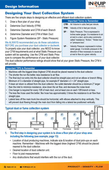
Design InformationDesigning Your Dust Collection SystemThere are five simple steps to designing an effective and efficient dust collection system.Important Terms to Remember1. Draw a floor plan of your shopCFM - Air Volume in cubic feet per minute.2. Determine Duct Velocity (FPM)FPM - Velocity of Air in feet per minute.3. Determine Diameter and CFM of each BranchSP -4. Determine Diameter and CFM of Main Duct5. Figure System Resistance (SP - Static Pressure)Static Pressure. This is expressed ininches water gauge. It is resistance to airat rest in a duct, and is also commonlycalled “resistance,” friction,” “friction loss”or “pressure loss”.We ALWAYS recommended you do these calculationsBEFORE you purchase your dust collector or ductwork. VP - Velocity Pressure: expressed in inchesTo properly size your dust collector, you NEED to knowwater gauge. It is kinetic pressure in thedirection of flow necessary to cause airyour CFM requirements and at what Static Pressure yourat rest to flow at a given velocity.system will be operating. Use the CFM and Static Pressure to compare the performance of your dust collector.The dust collector performance ratings should show that at your given Static Pressure, the CFM itwill provide.Important TIPS to Remember Machines with the biggest draw (highest CFM) should be placed nearest to the dust collector. The shorter the run the better, less resistance to air flow. The final duct run entry into the dust collector should be straight pipe and not an elbow or branch fitting.Minimum of 3 x diameter of straight pipe, for example 8" diameter x 3 24" straight pipe. If clean air return is utilized from the dust collector, the outlet diameter should be a minimum 2" largerthan the inlet to minimize resistance, slow down the air flow, and decrease the noise level. One hanger is required for every 10ft of main duct, and at least one on each 10ft branch or less. The less flex hose used the better; flex hose has approximately 3 times the resistance to air flow thanstraight pipe. Lateral tees off the main trunk line should be horizontal, with elbows attached to drop vertically. Thiswill prevent dust flowing through the main duct from falling into a lateral tee positioned vertically.Typical dust or fume collection system8"6"4"Table Saw1.4"Shaper8"5"5"RadialFloorsweep4"SanderDust CollectorThe first step in designing your system is to draw a floor plan of your shop areaincluding the following (see example, page 13): Location of dust producing machines, indicate size & location of dust pick-ups on eachmachine. Remember - Machines with the biggest draw (highest CFM) should be placednearest to the dust collector. Desired location of dust collector unit. Floor to joist measurement. Any obstructions that would interfere with the run of the duct.
Design Information2. Determine Duct Velocity (FPM)Use the chart below to determine the Velocity of your system.Type of DustMetalworking DustWoodworking DustOther Light DustVelocity in Branches4500 FPM4000 FPM4000 FPMVelocity in Main4000 FPM3500 FPM3500 FPM3. Determine Diameter and CFM of each BranchThere are several ways to determine the diameter of the branches. If the machine has a factory installed collar, the manufacturer has determined that themachine needs that size branch under normal circumstances. If the machine has a metric diameter outlet, convert it into inches, and round off to thenearest inch. When writing up your parts list you mayChart 1need to order a custom reducer.CFM requirements at specified velocity. If the outlet is rectangular you need to determine theDia. 3500 FPM 4000 FPM 4500 FPMequivalent round diameter. This will require a1701952203"Transition, see page 35.3003503904" If the branch is smaller than 3" dia., requirement is4755506105"high velocity vacuum, not volume dust collection, it is7007858806"950110012007"recommended to use a shop vac.1200140015708"Determine CFM requirement for each branch, use Chart 1.1550180019909"Under the proper velocity note the CFM of each branch. If19002200245010"working with wood dust, use 4000 FPM in branches.28003175360012"4. Determine Diameter of Main Duct14"380043004800Determine which machines are your primary machines. A primary machine is the machine(s)that will operate at the same time under the worst conditions. (If you normally operate two machines, but once a week need to operate a third machine at the same time, then you must size yoursystem for all three machines.) We generally highlight the primary machines on the drawing.Sizing the Main Trunk Line. When sizing the main trunk line start with the primary machine farthestfrom the dust collector. Run that size duct until the next primary branch enters the main. Increasethe main size at that junction to accommodate the CFM total of the two primaries. You will followthis practice all the way to the collector, sizing all primary junctions to accommodate total CFM of allprimaries at that point. Do not increase main duct size when a branch other than a primary enters.Your total CFM requirement is the total of all primary branches. When not using a primary machineyou will close blastgate and divert suction to a secondary machine.EXAMPLE - A 4" branch will be run from the Table Saw until it joins with the 4" branch from theShaper. At this point your main starts and you need to increase the pipe to handle the combinedCFM (350 350 700). Using the CFM Chart 1 look up 700 CFM under the appropriate velocity(3500 FPM in the main for wood dust), then look at the corresponding diameter (6"). Run 6" pipe inthe main from the Shaper until the branch of the Radial Saw joins the main.Here again you need to increase your main to handle the total CFM (700 550 1250 CFM). Usingthe chart again you will see that 1250 CFM is slightly more than volume for 8” diameter. Drop backto 8” diameter so as not to go below transport velocity. Run the 8” duct in your main from the RadialSaw to your Dust Collector.(continued on page 12)
Design Information5. Figure System Resistance (Static Pressure)Static pressure is resistance to flow caused by friction and the channeling of airflow through around pipe. If you turn on a dust collector with out anything attached to it - pipe, flex or filter bags, itwill pull max volume at free air without any resistance. Attach filter bags and 10' of pipe to the inletand you have added resistance. Add 20' more of pipe and so on - you increase resistance as youadd more pipe and fittings.It is the dust collector’s job to overcome the ductwork resistance and pull the proper amount ofCFM when you open a branch or branches in a central dust collection system. When you drink asoda with a regular straw it does not take much effort. If you have seen kids trying to drink a sodawith those curly straws, they strain trying to get the soda to flow. They are trying to overcome theresistance of the long run.You can run as much duct work in a system as long as the resistance has been compensated forand the CFM is delivered as required. “Inches of water” on a scale is used to measure the resistance in a duct system. It can be equated to the resistance to lift water by inches in a tube.The total static pressure is several factors added together. They are entry loss, dirty filter loss,static pressure of the worst branch duct, static pressure of main duct, and static pressure of thereturn duct.1. There are more complicated ways to figure the entry loss of your system, but we find it usuallyequals a loss of 1" watergauge. (Use 1" as a constant).2. If your system has filters, add in a 2" loss. (If you do not have filters add zero).3. The Worst Branch, is the branch with the greatest resistance. The branch with the greatest resistance is usually a smaller diameter with the most lineal footage of pipe and elbows. Static pressureof worst branch and main duct can be calculated by using Chart 2. Chart 2 is based on 100 feet ofpipe; therefore, you have to convertChart 2all elbows to an equivalent of pipe.Static Pressure based on 100' of Pipe.Elbow to Straight Pipe ConversionooTo convert 90 and 45 elbows to90o Elbow45o Elbowequivalent feet of pipe use Chart 2.Dia. 3500 FPM 4000 FPM 4500 FPM 1.5 Dia. Rad.1.5 Dia. Rad.When figuring the feet of pipe count5'2.5'3"7.510.012.0lateral type branches as 45o elbows. 4"6'3.0'5.57.08.5Flexhose has a lot of resistance depending on the corrugation. For thisreason we suggest you keep hoseto a minimum. Multiply your length offlexhose on your worst branch by 3for equivalent length of straight 5'15.0'If you are installing an indoor recirculating dust collector you need not calculate any more ductdiameters. If you are attaching ductwork to the exhaust side of your dust collector it is acceptedpractice to use a duct diameter two inches larger on the exhaust side than on the inlet side, thusminimizing exhaust and duct resistance. If clean air return duct is required, duct resistance shouldalso be calculated.Now you have all the information you need to make an educated decision in purchasing your dustcollector. You have determined the Velocity, CFM, Static Pressure and the size of the ductwork. Todevelop your list of materials required, go through the system; this time starting at the dust collectorand list each part you will need. Don’t forget pop rivets, hangers, strapping, caulking, and couplings.If you have any questions while you are designing your system give us a call at 800-367-3828.
Design Information - Example4"1. Draw a floor plan of your shop5"6"FloorsweepPlan View8"8"Table SawDust Collector4"5"ShaperRadial Saw4"Sander2. Determine Duct Velocity (FPM)Wood Dust 4000 FPM in Branch and 3500 PFM Main3. Determine Diameter and CFM of each Branch and Main DuctYou have 3 primary machines. You have assigned the branch diameter and CFM requirements.Table SawShaperRadial Saw4" Diameter4" Diameter5" Diameter4. Determine Diameter and CFM of Main Duct350 CFM350 CFM550 CFMTotal CFM of two 4" branches and one 5" branch pulling vacuum simultaneously 1,250 CFM5. Figure System Resistance (SP - Static Pressure)Determine Static Pressure (Inches of Water Gauge) in Worst Branch - 4" Table Saw.Description - 4" DiameterEquivalent to Straight PipeStraight Pipe20'2 - 90o Elbows12'2 - 45o Elbows6'5' Flexhose (3x)15'Total equivalent straight pipe after conversions53'350 CFM in 4" diameter 7" S.P. per 100'350 CFM in 4" diameter 3.71" S.P. per 53'Static Pressure in MAIN DUCT 6" and 8" The static pressure of the Main Duct is done the same way, except youfigure it out for each diameter in the Main, starting farthest away and working toward the collector.Description - 6" DiameterEquivalent to Straight PipeStraight Pipe20'Total equivalent straight pipe after conversions20'700 CFM in 6" diameter 3.5" S.P. per 100’700 CFM in 6" diameter .70" S.P. per 20’Description - 8” DiameterEquivalent to Straight PipeStraight Pipe25'2 - 90o Elbows30'Total equivalent straight pipe after conversions55'1,250 CFM in 8" diameter 2.4" S.P. per 100'1,250 CFM in 8" diameter 1.3" S.P. per 55'(8" Diameter runs to self contained Dust Collector)Total Static Pressure 1" (entry loss) 2" (filters) 3.71" (worst branch) .70" (6” Main) 1.3" (8” Main) 8.71" SPInches Water Gauge. System Requirement: 1,250 CFM at 8.71" SPWG
Helpful Installation InformationInstallation of Spiral Pipe and Fittings Fittings and Small-End couplings are made small end to slip inside pipe and flexhose. Fitting-to-Fitting connections are made by using a large end coupling or a short length of spiral pipe. To facilitate installation, assemble groupings of pipe and fittings on floor. Minimize amount of connections on ladder. It is recommended that you place silicone caulking about one inch in and around the inside of the spiralpipe before you assemble any fitting. Secure the connection with steel (not aluminum) pop rivets.Place a second bead of silicone around the outside of the connection, and smooth around connection.Pipe-To-Pipe ConnectionSpiral pipes are connected togetherby a sleeve type coupling (Part No.COUP). The coupling has a small-endand is slipped into the pipe sections.See page 18.Fitting-To-Fitting ConnectionFitting-to-Fitting con nec tions can bemade by cut ting a short length ofspi ral pipe and us ing this length ofpipe as a large end cou pling or byor der ing a large end cou pling (PartNo. COU2). See page 18.Fitting-To-Pipe ConnectionAll fittings are sized to slip into matingpipe sections or flex hose. No ad di tion al cou pling will be needed.Friction Loss and Air LeakageTwo problems with high velocity systems are friction loss and air leakage. The installer has toinstall the high-pressure system without causing possible friction losses or air leakage problems.Do not crimp the ends of the fittings to make assembly easier. The crimping puts interference inthe air stream, which adds friction loss to the system. Crimping can also create noise problems.Excessive clearances in sizing of the pipe and fittings can cause problems in sealing the systemto make it airtight. Hunting and patching leaks in an installed system is tedious and stressful.Your duct and fittings are sized to fit tightly for 3 good reasons.1. The joint has a minimum friction loss condition.2. The tight fit makes the joint easy to seal against air leakage3. Noise is reduced with a tighter joint.Connection of duct and fittingStarting the fitting into the duct.Starting the collar into duct, impactat A.AA sharp blow by a sheet met alhammer or mallet on the top of thefitting collar can help the collar toseat into the duct. Be careful not todent the collar.When a sub-assembly is puttogether on the floor, raise the endof the duct to support it off the floorwith a piece of wood. Tilt the fittingslightly and start the bottom part ofthe fitting collar into the duct.Starti
Typical dust or fume collection system. 2. Determine Duct Velocity (FPM) Use the chart below to determine the Velocity of your system. 3. Determine Diameter and CFM of each Branch There are several ways to determine the diameter of the branches . If the machine has a factory installed collar, the manufacturer has determined that the machine needs that size branch under normal circumstances .
