Transcription
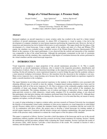
Visuohaptic Borescope Inspection Simulation Training: ModelingMulti-Point Collision Detection/Response and Evaluating Skills TransferDeepak Vembar, Andrew Duchowski Melissa Paul, Anand GramopadhyeCarl WashburnSchool of ComputingIndustrial EngineeringAircraft Maintenance ProgramClemson UniversityClemson UniversityGreenville Technical CollegeFigure 1: Visual comparison of intersection response of actual and virtual probe at 30 angle of incidence (for visualization purposes only—theuser’s viewpoint is from the probe’s tip); inspection of PT-6 aircraft engine using actual borescope, with operator’s view of the camera output.A BSTRACTResults are presented from a transfer effects study of a visuohapticborescope simulator developed for non-destructive aircraft inspection training. The borescope simulator supports multi-point collision detection to effect haptic feedback as the virtual probe slidesalong and collides with rigid surfaces. Such probe maneuvering isshown to be a significant aspect of the inspection task that benefitsfrom training, regardless of whether a real or virtual probe simulator is used to provide the training.Index Terms: I.3.6 [Computer Graphics]: Methodology andTechniques—Ergonomics; J.4 [Computer Applications]: Socialand Behavioral Sciences—Psychology.1 I NTRODUCTIONIn aircraft maintenance, visual inspection forms an important partof non-destructive testing [2] accounting for almost 80% of plannedmaintenance of large aircraft [7]. Due to minimal equipment costs,visual inspection is usually the quickest and most economical wayof obtaining a preliminary evaluation of the condition of an aircraft[6]. Inspection of easily accessible regions of an aircraft such ascargo bay and fuselage require simple equipment, such as a flashlight and magnifying glass. Enclosed components, such as an aircraft engine, present a challenge as the parts are not easily accessible without a complete teardown of the equipment.To enable a technician to inspect an area that is inaccessible byother means, a device known as a borescope is used. A borescopeis an optical device consisting of a rigid or flexible tube with aneyepiece or video screen at one end and a miniaturized camera orlens system at the other end. The two components are linked together by a fiber optic cable which carries a video signal and servesto illuminate the engine component under inspection.Theoretical knowledge of borescope inspection is generallygained in the classroom. On-the-job training by a more experi e-mail:duchowski@clemson.eduenced inspector is used to bridge the gap from an academic settingto a more practical workplace environment. However, this transition from the classroom to the workplace is not easy. Many noviceinspectors face a steep learning curve because they lack the requiredhands-on experience required to make a smooth transition to theworkplace. The major limitation in providing more practical experience to students is the prohibitive cost associated with obtainingdifferent types of aircraft to train the students.Virtual Reality (VR) simulators have been used to train novicesin a wide range of skills, including flight and surgery [3, 16]. Consisting of 3D models rendered by a computer, simulators attempt topresent a realistic, real-time environment with instantaneous performance feedback. Training sessions can be customized to suit individual needs and skill levels. In addition to purely visual feedback,simulators can be augmented with auditory and tactile feedback fora more immersive experience. It is hypothesized that functional realism [15] of the VR simulation is necessary for the skills to transfereffectively from the virtual testbed to the real world.Earlier, we described a novel virtual borescope inspection simulator [29]. Using 3D models of engine components, we developedthe simulator to train novice borescope inspection technicians inthe good practices of engine inspection. User interaction was testedwith a novel haptic device as well as with off-the-shelf devices suchas the Novint Falcon. By providing probe tip contact feedback anda realistic probe camera model, we established the benefit of forcefeedback by observing improved task completion times as well asreduced probe intersections in the simulator. However, some participants noted they did not receive any force feedback from the hapticdevice when inserting and maneuvering the virtual probe throughthe engine model.Presently, a mathematical model for multi-point collision detection and response along the length of the virtual probe is derived.Previously, multiple points of contact were detected, but force feedback was calculated only at the tip of the probe. As visualized inFigure 1, computation of forces along the probe’s length allows provision of sliding contact feedback to the user as the probe grazessurfaces in the virtual environment. The sliding contact feedback,augmenting tip contact feedback, is thought to further decrease performance uncertainty by affording the user with a richer compar-
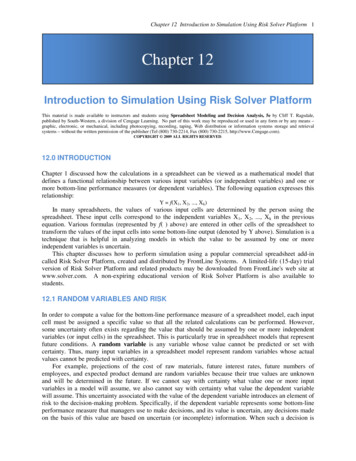
ison to expected kinesthetic sensations, and thus hypothesized toreduce functional task difficulty [17]. We do not test this hypothesisdirectly, however.While sliding contact is tacitly assumed to enrich haptic feedback, in this paper we focus on the evaluation of training transfer effects on real world task performance. Prior evaluation of theborescope simulator was limited to representative inspection tasksin the simulator. We did not perform any evaluation of task performance during an actual engine inspection. Here, quantitativeand qualitative measures are reported from novice students inspecting a PT6 engine after undergoing one of three training methods:classroom-only training, simulator training, or hands-on trainingwith the video borescope. Results indicate that the psychomotorskills required for maneuvering the borescope probe through theengine can be successfully obtained through simulator training.2P HYSICALLY - BASED P ROBE M ODELWhile graphics rendering focuses on the visual appearance of themodel, by computing appropriate force/torque interaction, hapticrendering simulates force feedback to allow the human operatorto feel the geometry, surface, and material properties of the object. There are two major points of asymmetry between haptic andgraphics rendering: collision detection and rate of dynamic simulation. Unlike graphics rendering which only needs to model object deformation to “look” realistic, haptic rendering has to be builtupon a more accurate physics-based model. While real-time update rates for graphics rendering are about 30-60 frames per second,smooth haptic rendering requires an update rate of almost 1 KHz.In haptic interface design, the deciding factor in choosing thebest collision algorithm is the speed of calculation to determinewhether a collision has occurred. Inter and intra-object collisionsplay an important role in the overall behavior of the interacting objects in a simulation. The choice of the contact model, single pointversus multi-point contact detection, and external forces such asstatic and dynamic friction, influence the post-impact motion of theinteracting objects. Quick changes in haptic forces when objects intersect can cause artificial growth of energy and lead to instabilitiesof the simulation [27].2.1Prior workPrior work in the medical simulation community has led to the development of fast, scalable, multi-object, multi-point collision simulation and response algorithms [4]. Intersections of the borescopeprobe with the engine can occur at multiple points along the inserted length. Probe deformations occur due to collisions with theengine, and the amount of deformation is dependent on the positionwithin the engine, force applied at the point of incidence, as wellas the angle of incidence of the probe at the point of contact. Unlike medical procedures, which use a catheter, such as in vascularand cardio-thoracic surgery, interaction of the borescope probe withthe engine consists of a semi-flexible body interacting with a rigidbody. Instead of computing elastic and deformation forces experienced by the catheter due to collision with soft tissues, computationof deformations can be limited to the interaction of the semi-flexibleprobe with rigid surfaces.Prior work, especially in radiology and vascular surgery [5, 24],has resulted in visual and behaviorally realistic models for simulating catheters, guidewires and surgical threads. Deformable objects have been simulated using physically-based mass-spring models following Newtonian Laws of motion. The catheter or surgicalthread is modeled as a linear system of point masses connectedby linear and torsional springs between two adjacent points. Using explicit or implicit numerical integration, the velocities andpositions of each point mass are computed over the duration ofthe simulation. Since collision detection is computationally expensive, methods such as bounding spheres, axis-aligned boundingFigure 2: Visualization of node chain used to model the borescope.boxes (AABBs) or bounding volume hierarchies (BVHs) are usedto speedup collision testing.The main advantage of mass-spring models is that they are fast,easy to implement and, with appropriate collision detection algorithms, can support haptic rates exceeding 1 KHz. Several previousexamples exist, including Dawson et al.’s [12] catheter simulationbased on a multi-body system composed of a set of rigid bodies andjoints, Pai’s [25] one-dimensional deformable objects modeled asCosserat rods, Brown et al.’s [8] physical simulation model calledFollow The Leader (FTL), Alderliesten et al.’s [1] simulation ofguidewire insertion into the vascular system, Wang et al.’s [30, 31]physics-based simulation of a thread model, and Kubiak et al.’s [18]real-time simulation of thread dynamics with all the relevant aspectsof the physics model of the thread, including stiffness, bending, torsion and self-collision, and output forces for haptic feedback. Thestability of these systems depends to a great extent on the simulation parameters chosen. Simulation of interactions of rigid objectswith large stiffness requires a small timestep for numerical stability,which in turn affects the interactive rate of the simulation. Biological materials, such as tissues, exhibit non-linear elasticity and arenot at all homogeneous, so choosing realistic simulation parametersfor the spring constants is time consuming.In mass-spring systems, the object is represented as a set of discrete point masses connected by springs. The initial formulationis discrete and any deformations of the model changes the levelof potential energy in the model. Finite Element Models (FEMs),on the other hand, have been proposed as a solution to the difficulties with simplified physically-based systems. FEMs provide acontinuous formulation that relates the model deformation to energy and compute deformation over the entire volume instead ofat discrete points. They are more accurate than mass-spring systems, but at the expense of added computational complexity. Examples include those of Contin et al. [11], who developed a real-timemodel for deformation of devices such as catheters and guidewiresduring navigation inside complex vascular networks, and Lenoir etal. [22], who used a composite model to realistically simulate acatheter/guidewire system,In addition to the graphical simulation of deformable objects,Laycock and Day [20, 21] have presented multiple algorithms tomodel the interactions of a deformable tool with a rigid body. Thedeformable tool, in this case an elastic rod, is modeled as a linearchain of 6-DOF nodes and its behavior is calculated using FEManalysis. Translational and rotational properties as well as realistic deformation of the beam elements were implemented. However,the simulation performance degraded as the number of nodes increased, due to the computational complexity of increased collisiondetection required for the additional nodes.Our implemented probe model (Figure 2) is based on GlobularElastic Models (GEMs) [10] used to simulate deformable objects,but instead of computing the medial axis transform, the borescope
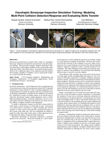
Direction of probe motionProxy positionProbe articulationcontrolled by userAft nodesAmount ofsurfacepenetrationRigid surfaceGuide tubeHapticInterfacePoint (HIP)Foremost nodeNodes in guide tube, fixedF proxyNodes controlling probe articulationNodes used in dynamic simulationFigure 5: Single point contact with position of Haptic Interface Point(HIP) and proxy position.Figure 3: Representation of the linear chain of nodes used to modelthe borescope probe. Each adjacent pair of nodes is connected by aset of linear and angular springs. llrFF l l l rF ke llNode 0Node 1F1F0θ1θ0τ i kf ( θlrτ0π/2 )τFi ilrτ1Figure 4: Elongation and torsion due to linear and angular springsbetween two adjacent nodes of the probe.probe is modeled as a discrete linear chain of point mass nodes (p0 ,. . . , pn ) with damped linear and angular springs connecting adjacent nodes. We implemented a simple numerical integrator usingEuler’s method, as opposed to using middleware APIs such as Havok Physics or the Open Dynamics Engine (ODE). We describe themodel in the following section.2.2ImplementationSuccessful implementation of a physically based probe model requires fast detection of collisions, computation of interacting forcesfrom an internal mass-spring model of the simulation as well as external forces due to the point-proxy model, and collision responsefrom the computed forces. We implemented a hybrid probe modelcombining the deformation modeling of a linear mass-spring system, and collision detection and response through a chain of pointproxy nodes.2.2.1Linear elongation springs between adjacent nodes provide axialcompression and elongation, and angular springs simulate flexionand torsion of the probe. The behavior of linear and angular springsis based on Hooke’s Law. The rest length b
borescope simulator was limited to representative inspection tasks in the simulator. We did not perform any evaluation of task per-formance during an actual engine inspection. Here, quantitative and qualitative measures are reported from novice students inspect-ing a PT6 engine after undergoing one of three training methods: