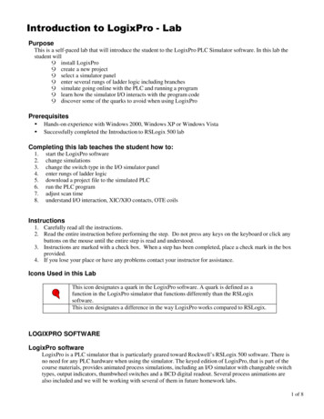
Transcription
EC-LabSoftwareUser's ManualVersion 10.1x – February 2011
Equipment installationWARNING!: The instrument is safety ground to the Earth through the protectiveconductor of the AC power cable.Use only the power cord supplied with the instrument and designed for the goodcurrent rating (10 Amax) and be sure to connect it to a power source provided withprotective earth contact.Any interruption of the protective earth (grounding) conductor outside the instrumentcould result in personal injury.Please consult the installation manual for details on the installation of the instrument.General descriptionThe equipment described in this manual has been designed in accordance with EN61010and EN61326 and has been supplied in a safe condition. The equipment is intended forelectrical measurements only. It should be used for no other purpose.Intended use of the equipmentThis equipment is an electrical laboratory equipment intended for professional and intendedto be used in laboratories, commercial and light-industrial environments. Instrumentation andaccessories shall not be connected to humans.Instructions for useTo avoid injury to an operator the safety precautions given below, and throughout themanual, must be strictly adhered to, whenever the equipment is operated. Only advanceduser can use the instrument.Bio-Logic SAS accepts no responsibility for accidents or damage resulting from any failure tocomply with these precautions.GROUNDINGTo minimize the hazard of electrical shock, it is essential that the equipment be connected toa protective ground through the AC supply cable. The continuity of the ground connectionshould be checked periodically.ATMOSPHEREYou must never operate the equipment in corrosive atmosphere. Moreover if the equipmentis exposed to a highly corrosive atmosphere, the components and the metallic parts can becorroded and can involve malfunction of the instrument.The user must also be careful that the ventilation grids are not obstructed. An externalcleaning can be made with a vacuum cleaner if necessary.Please consult our specialists to discuss the best location in your lab for the instrument(avoid glove box, hood, chemical products, ).
AVOID UNSAFE EQUIPMENTThe equipment may be unsafe if any of the following statements apply:- Equipment shows visible damage,- Equipment has failed to perform an intended operation,- Equipment has been stored in unfavourable conditions,- Equipment has been subjected to physical stress.In case of doubt as to the serviceability of the equipment, don’t use it. Get it properly checkedout by a qualified service technician.LIVE CONDUCTORSWhen the equipment is connected to its measurement inputs or supply, the opening ofcovers or removal of parts could expose live conductors. Only qualified personnel, whoshould refer to the relevant maintenance documentation, must do adjustments, maintenanceor repairEQUIPMENT MODIFICATIONTo avoid introducing safety hazards, never install non-standard parts in the equipment, ormake any unauthorised modification. To maintain safety, always return the equipment toBio-Logic SAS for service and repair.GUARANTEEGuarantee and liability claims in the event of injury or material damage are excluded whenthey are the result of one of the following.- Improper use of the device,- Improper installation, operation or maintenance of the device,- Operating the device when the safety and protective devices are defectiveand/or inoperable,- Non-observance of the instructions in the manual with regard to transport,storage, installation,- Unauthorized structural alterations to the device,- Unauthorized modifications to the system settings,- Inadequate monitoring of device components subject to wear,- Improperly executed and unauthorized repairs,- Unauthorized opening of the device or its components,- Catastrophic events due to the effect of foreign bodies.
IN CASE OF PROBLEMInformation on your hardware and software configuration is necessary to analyze and finallysolve the problem you encounter.If you have any questions or if any problem occurs that is not mentioned in this document,please contact your local retailer (list available following the link: .html). The highly qualified staff will be glad to help you.Please keep information on the following at hand:- Description of the error (the error message, mpr file, picture of setting orany other useful information) and of the context in which the erroroccurred. Try to remember all steps you had performed immediatelybefore the error occurred. The more information on the actual situation youcan provide, the easier it is to track the problem.- The serial number of the device located on the rear panel device.Model: VMP3s/n : 0001Power: 110-240 Vac 50/60 HzFuses: 10 AF Pmax: 650 W-The software and hardware version you are currently using. On the Helpmenu, click About. The displayed dialog box shows the version numbers.The operating system on the connected computer.The connection mode (Ethernet, LAN, USB) between computer andinstrument.
General safety considerationsThe instrument is safety ground to the Earth throughthe protective conductor of the AC power cable.Class IUse only the power cord supplied with the instrumentand designed for the good current rating (10 A max)and be sure to connect it to a power source providedwith protective earth contact.Any interruption of the protective earth (grounding)conductor outside the instrument could result inpersonal injury.Guarantee and liability claims in the event of injury ormaterial damage are excluded when they are the result ofone of the following.- Improper use of the device,- Improper installation, operation or maintenance of thedevice,- Operating the device when the safety and protectivedevices are defective and/or inoperable,- Non-observance of the instructions in the manual withregard to transport, storage, installation,- Unauthorised structural alterations to the device,- Unauthorised modifications to the system settings,- Inadequate monitoring of device components subjectto wear,- Improperly executed and unauthorised repairs,- Unauthorised opening of the device or its components,- Catastrophic events due to the effect of foreign bodies.ONLY QUALIFIED PERSONNEL should operate (orservice) this equipment.
EC-Lab Software User's ManualTable of contentsEquipment installation . iGeneral description . iIntended use of the equipment . iInstructions for use . iGeneral safety considerations . iv1.Introduction. 52.EC-Lab software: settings . 72.1Starting the Program . 72.2Preparing and Running an Experiment with EC-Lab software . 92.2.1 EC-Lab main window . 92.2.1.1 Settings tool bar . 102.2.1.2 The graphic tool bars . 112.2.1.3 Status tool bar . 112.2.1.4 Current values tool bar . 112.2.1.5 The parameter settings frame. 132.2.1.6 Right click on the “Parameter settings” window . 132.2.2 The bar menu. 142.2.3 Selecting a technique . 172.2.4 Parameter Settings . 192.2.5 Cell characteristics . 232.2.5.1 Standard “Cell Characteristics” window . 232.2.5.2 Cell characteristic window in column format . 252.2.5.3 Battery “Cell Characteristics” window . 252.2.6 Advanced Settings . 282.2.6.1 Compliance . 302.2.6.2 Electrodes connections . 312.2.6.2.1 CE to Ground connection mode . 312.2.6.2.2 WE to Ground connection mode . 322.2.6.3 Experiment limits . 322.2.6.4 Miscellaneaous. 332.2.6.4.1 Text export . 332.2.6.4.2 Filter . 332.2.6.4.3 Smooth with sliding average. . 332.2.6.4.4 Create one data file per loop . 332.2.6.5 Filtrering . 332.2.6.6 Channel . 332.2.6.7 Ultra low current option. 342.2.7 Accepting and saving settings . 362.2.8 Running acquisition . 362.3Available commands during the run. 372.3.1 Stop and Pause . 372.3.2 Modifying an experiment in progress . 372.4Multi-channel selection: Grouped, Synchronized or stack experiments . 372.4.1 Grouped or synchronized experiments . 382.4.2 Stack experiments. 392.5Batch mode . 412.6Data properties . 422.6.1 Type of data files . 422.6.2 Variables description . 421
EC-Lab Software User's Manual2.6.3 Data recording . 442.6.4 Data Saving . 452.7Changing the channel owner . 452.8Virtual potentiostat . 452.9Configuration options. 472.9.1 General options. 472.9.2 Warning options . 482.9.3 Text Export options . 492.9.4 Color options . 502.9.5 Reference electrode options . 502.9.6 Tool bars options . 523.EC-Lab software: Graphic Display. 533.1The Graphic window . 533.1.1 The graphic window right click menu . 533.1.2 Loading a data file . 563.1.3 EC-Lab graphic display . 583.1.4 Graphic tool bars . 593.1.5 The data file and plot selection window . 593.2Graphic facilities . 613.2.1 Cycles/Loops visualization . 613.2.2 Show/Hide points . 623.2.3 Add comments on the graph . 623.2.4 Three-Dimensional graphic . 643.2.5 Graph properties . 663.2.6 The LOG (History) file . 703.2.7 Copy options . 703.2.7.1 Standard copy options . 713.2.7.2 Advanced copy options . 713.2.8 Print options . 713.2.9 Multiple graphic windows . 723.2.9.1 Multi-graphs in a window . 723.2.9.2 Multi windows . 733.2.10Graph Representation menu . 743.2.10.1Axis processing . 753.2.10.2How to create your own graph representation for a specific technique? . 773.2.10.3How to create a Graph Style? . 783.3Graph Tools . 803.3.1 Zone selection. 813.4Analysis Menu . 823.4.1 Math Menu . 843.4.1.1 Min and Max determination . 843.4.1.2 Linear Fit . 853.4.1.3 Circle fit . 863.4.1.4 Linear interpolation . 873.4.1.5 Subtract files . 883.4.1.6 Integral . 893.4.1.7 Fourier transform . 903.4.1.8 Filter . 923.4.1.9 Multiexponential Sim/Fit . 933.4.2 General Electrochemistry Menu . 943.4.2.1 Peak Analysis . 942
EC-Lab Software User's Manual3.4.2.1.1 Baseline selection . 953.4.2.1.2 Peak analysis results . 963.4.2.1.3 Results of the peak analysis using a linear regression baseline . 963.4.2.1.4 Results of the peak analysis using a polynomial baseline . 983.4.2.2 Wave analysis . 993.4.2.3 CV sim. 1003.4.3 Electrochemical impedance Spectroscopy menu . 1043.4.3.1 Impedance data analysis: Simulation, Fit and Kramers-Kronig criterion. 1043.4.3.1.1 Electric equivalent elements: description . 1053.4.3.1.2 Resistor: R . 1053.4.3.1.3 Inductor: L . 1063.4.3.1.4 Capacitor: C. 1063.4.3.1.5 Constant phase element: Q . 1073.4.3.1.6 Warburg element for semi-infinite diffusion: W . 1073.4.3.1.7 Warburg element for convective diffusion: W d. 1083.4.3.1.8 Linear diffusion element: M . 1083.4.3.1.9 Gerischer element: G . 1093.4.3.2 Simulation: ZSim . 1103.4.3.2.1 ZSim window . 1103.4.3.2.2 Circuit selection . 1123.4.3.2.3 Description code . 1123.4.3.3 Fitting: ZFit . 1143.4.3.3.1 Zfit selection window. 1153.4.3.3.2 Fitting methods . 1153.4.3.3.3 Application . 1173.4.3.3.4 Fit on successive cycles . 1183.4.3.3.5 Pseudo-capacitance . 1193.4.3.3.6 Additional plots . 1213.4.3.4 Mott-Schottky fit. 1223.4.3.4.1 Mott-Schottky relationship and properties of semi-conductors . 1223.4.3.4.2 The Mott-Schottky plot . 1233.4.3.4.3 The Mott-Schottky Fit. 1243.4.3.4.4 Saving Fit and analysis results. 1253.4.3.5 Kramers-Kronig transformation . 1263.4.4 Batteries menu . 1283.4.5 Photovoltaic/fuel cell menu. 1283.4.6 Corrosion menu . 1293.4.6.1.1 Linear microPolarization (LP) . 1303.4.6.1.2 Constant Amplitude Sinusoidal microPolarization (CASP) . 1303.4.6.1.3 Variable Amplitude Sinusoidal microPolarization (VASP). 1313.4.6.2 Rp Fit . 1323.4.6.3 Tafel Fit . 1343.4.6.3.1 Tafel Fit window . 1343.4.6.3.2 Corrosion rate . 1363.4.6.3.3 Minimize option . 1363.4.6.4 Constant Amplitude Sinusoidal microPolarization fit (CASP fit) . 1373.4.6.5 Variable Amplitude Sinusoidal microPolarization fit (VASP fit) . 1393.4.6.6 Electrochemical Noise Analysis . 1393.4.6.7 Other corrosion processes. 1413.5Data and file processing . 1413.5.1 Data processing . 1423.5.1.1 Process window . 1423.5.1.2 Additional processing options . 1433.5.1.3 The derivative process . 1443
EC-Lab Software User's Manual3.5.1.4 The compact process . 1453.5.1.5 Capacity and energy per cycle and sequence . 1463.5.1.6 Summary per protocol and cycle . 1473.5.1.7 Constant power protocol summary . 1483.5.1.8 Polarization resistance . 1493.5.1.9 Multi-pitting statistics . 1513.5.2 Data File import/export functions . 1523.5.2.1 ASCII text file creation and exportation . 1523.5.2.2 ZSimpWin exportation . 1533.5.2.3 ASCII text file importation from other electrochemical software . 1533.5.2.4 FC-Lab data files importation. 1553.6Reports. 1554.Linked experiments . 1584.1Description and settings . 1584.2Applications . 1594.2.1 Linked experiments with EIS techniques . 1594.2.2 Application of linked experiments with ohmic drop compensation . 1615.Advanced features. 1635.1Maximum current range limitation (2.4 A) on the standard channel board . 1635.1.1 Different limitations. 1635.1.2 Application to the GSM battery testing . 1645.2Optimization of the potential control resolution . 1665.2.1 Potential Control range (span) . 1665.2.2 Setting of the Working Potential window . 1675.3Measurement versus control current range . 1685.3.1 The potentio mode . 1685.3.2 The galvano mode . 1685.3.3 Particularity of the 1 A current range in the galvano mode . 1695.3.4 Multiple current range selection in an experiment . 1695.4External device control and recording . 1705.4.1 General description . 1705.4.2 Rotating electrodes control. 1725.4.2.1 Control panel . 1735.4.3 Temperature control . 1745.4.4 Electrochemical Quartz Crystal Microbalance coupling . 1755.5Preconditioning methods before an electrochemical experiment . 1765.5.1 Equilibrium state establishment . 1765.5.2 Preconditioning methods . 1775.5.2.1 Mechanical modification . 1775.5.2.2 Electrochemical modifications . 1775.5.3 EC-Lab facilities for the pretreatment before an electrochemical measurement . 1776.Troubleshooting . 1786.16.26.3Data saving: . 178PC Disconnection: . 178Effect of computer save options on data recording: . 1787.Glossary . 1798.Index .
General safety considerations Class I The instrument is safety ground to the Earth through the protective conductor of the AC power ca
