Transcription
NXP SemiconductorsDocument identifier: DRM172Reference ManualLLC Resonant Converter Design UsingMC56F8xxxxRev. 1, 10/2020
NXP SemiconductorsContentsChapter 1 Introduction. 31.1 Application outline. 31.2 Resonant converter topologies and features.31.3 MC56F8xxxx controller advantages and features. 6Chapter 2 System description.92.1 Structure. 92.2 Modulation mode. 102.3 Control loop introduction.13Chapter 3 Hardware design. 153.1 Specifications. 153.2 Resonant network design. 153.3 Transformer design. 163.4 Power circuits and drivers. 173.5 PCB layout considerations. 19Chapter 4 Software design. 234.1 Parameter normalization. 234.2 State machine.234.3 Control timing. 264.4 Drive signal generation logic. 284.5 Fault protection.294.6 Use of peripherals. 294.7 Code runs in RAM. 304.8 Bootloader. 32Chapter 5 Testing. 355.1 System efficiency.355.2 Dynamic performance. 375.3 Current limitation function.385.4 Output voltage ripple. 39Chapter 6 Revision history.41Reference ManualLLC Resonant Converter Design Using MC56F8xxxx, Rev. 1, 10/20202 / 42
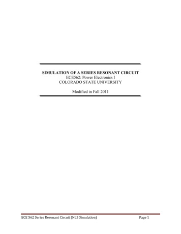
NXP SemiconductorsChapter 1Introduction1.1 Application outlineThis reference design describes an LLC resonant converter design using MC56F8xxxx DSC.This document focuses on the key part design of the LLC resonant converter. The system description includes:— system structure— modulation modes— control loop The hardware design includes:— resonant network design— transformer design— PCB layout consideration The software design includes:— system state machine— control timing— drive signal generation logic— fault protection— bootloader1.2 Resonant converter topologies and featuresThe demand for increasing power density of switched-mode power supplies pushes designers to use a higher switchingfrequency. But a high switching frequency significantly increases switching losses at Pulse Width Modulated (PWM) converters.It decreases the efficiency. Besides, with larger heatsink or forced cooling, it wastes the spaces saved by using smaller passivecomponents. Therefore, the SMPS designers are looking for solutions to decrease switching losses.One of the possible solutions is to use the resonant converter topologies. The resonant converter uses a resonant circuit in theconversion path. Figure 1 shows the typical structure of the resonant converter. The switching network generates a square wavevoltage output. This voltage pattern feeds the resonant tank. The resonant tank consists of a serial or a parallel combination of Land C passive components. There are several combinations of two or three L and C passive components used in the resonanttank. The type of resonant tank and its connection to the load defines the resonant converter behaviors. Due to the resonant tank,the semiconductor switches can operate at zero voltage or current switching condition. This phenomenon significantly reducesswitching losses and allows the converter operation at high switching frequencies.Reference ManualLLC Resonant Converter Design Using MC56F8xxxx, Rev. 1, 10/20203 / 42
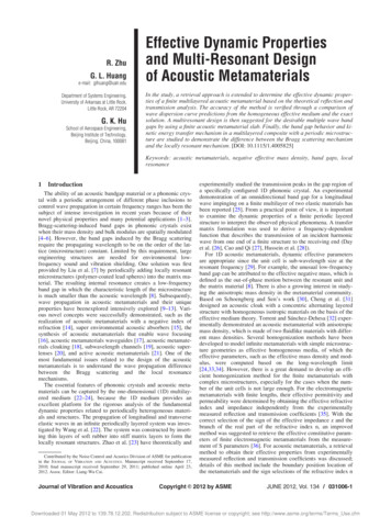
NXP SemiconductorsIntroductionFigure 1. Resonant converter principleThe most common known resonant topologies are a Serial Resonant Converter (SRC) and Parallel Resonant Converter (PRC). Figure 2 shows the SRC. The resonant tank consists of a serial connected inductor Lr and capacitor Cr. The load RL is alsoconnected in series with the resonant tank. In the serial resonant converter, the resonant tank and load creates a voltagedivider. Because the resonant tank impedance is frequency dependent, the output voltage of the SRC can be controlled byswitching frequency. At the DC or low switching frequency the resonant tank has high impedance in comparison with the loadimpedance and the output voltage is low. Increasing the switch frequency also increases the output voltage. At the resonantfrequency, the voltage drop on the resonant tank is equal to zero and thus the output voltages are equal to the input voltage.Continuing over the resonant frequency, the output voltage starts to decrease. This is because the resonant tank impedanceincreases against to the load impedance. The operation over the resonant frequency is preferred, even if the output voltageregulation is possible over or below resonant frequency. The inductive character of the resonant frequency allows to achieveZero Voltage Switching (ZVS), which is preferred for MOSFET transistors.The output voltage regulation is also limited by the load value. If the load is very low, the load impedance is high in comparisonwith the resonant tank. Keeping the desired voltage at the output becomes difficult. Theoretically the switching frequency canbe infinite, but practically there is some maximal frequency limit. Therefore, the output voltage regulation at light or no loadcondition is very limited.Reference ManualLLC Resonant Converter Design Using MC56F8xxxx, Rev. 1, 10/20204 / 42
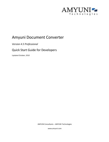
NXP SemiconductorsIntroductionFigure 2. SRC topology Figure 3 shows another well-known topology - PRC. The parallel converter uses the same resonant tank as the serial resonantconverter, the serial connection of inductor Lr and capacitor Cr. The PRC differs in load connection to the resonant tank. In thiscase, the load is connected in parallel with the capacitor Cr. In this configuration, the voltage divider consists of impedance ofthe inductor Lr and impedance of parallel combination of the capacitor Cr and the load RL. This means that both parts top andbottom impedance of the voltage divider are frequency dependent. At the DC or low switching frequency, the output voltage ofthe PRC is equal to input voltages. With the increase of the switching frequency, the output voltage also increases due to thecharacteristic of the resonant tank. The maximal output voltage is achieved at a resonant frequency, where the output voltageis Q times higher than the input voltage. The Q is a quality factor of the resonant tank. Over the resonant frequency, the outputvoltage falls, because the inductor impedance becomes more dominant against the capacitor impedance.The PRC can control the output voltage even at no load conditions. In this case, the PRC is comprised of a resonant tank only.On the other hand, the permanent connection of the resonant tank to the switch network brings some drawbacks at nominaloperation. At nominal load the parallel converter operates close to the resonant frequency and thus the resonant tanks havethe lowest impedance. This also means a high circulating current through the resonant tank. The parallel converter is alsosuggested to operate over the resonant frequency due to ZVS conditions.Figure 3. PRC topologyReference ManualLLC Resonant Converter Design Using MC56F8xxxx, Rev. 1, 10/20205 / 42
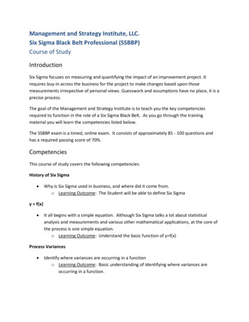
NXP SemiconductorsIntroductionBesides the two part resonant tanks, there are almost 40 possibilities of three part resonant tanks. The most popular memberof three part tanks is the LLC resonant converter. The resonant tank consists of two inductors Lr, Lm and one capacitor Cr (seeFigure 4). The load is connected in parallel to the inductor Lm. The LLC resonant converter solves all drawbacks mentionedabove. At no load conditions the output voltage can still be controlled by a voltage drop over inductor Lm. Also at resonantfrequency, the current is limited by the Lm inductor; therefore, the circulating current through the resonant circuit can be kepton an acceptable level. Another advantage of the LLC resonant converter is that it can operate under ZVS condition over thewhole load range. Table 1 lists the summary of the key features of all mentioned resonant converters.Figure 4. LLC resonant converter topologyTable 1. Resonant converters comparison—SRCPRCLLCZVS operationAbove fr (resonant frequency)onlyAbove fr onlyYesOperation without loadNoYes, but high lossesYesOperation at frNoNoYesOperation at wide input rangeHigh lossesHigh lossesYes1.3 MC56F8xxxx controller advantages and featuresThe 56F8xxxx microcontroller is a member of the 32-bit 56800EX core-based Digital Signal Controllers (DSCs). Each device inthe family combines, on a single chip, the processing power of a 32-bit DSP and the functionality of a microcontroller with a flexibleset of peripherals. Due to its cost-effectiveness, configuration flexibility, and compact program code, 56F8xxxx is well-suited formany consumer and industrial applications.With numerous, highly-integrated peripherals and powerful processing capabilities, the 56F8xxxx is a low-cost family especiallyuseful for Switched Mode Power Supplies (SMPSs), advanced motor control (including dual motor control), smart appliances,Uninterruptible Power Supplies (UPSs), photovoltaic systems, power distribution systems, wireless charging, and medicalmonitoring applications.The following list summarizes the superset of features across the entire 56F8xxxx family. 56800EX 32-bit DSC core Up to 100MIPS at 100 MHz core frequencyReference ManualLLC Resonant Converter Design Using MC56F8xxxx, Rev. 1, 10/20206 / 42
NXP SemiconductorsIntroduction Protects supervisor programs and resources from user programs One/Two 8-channel eFlexPWM module(s) with NanoEdge placement and enhanced capture Two 8-channel 12-bit cyclic ADC One windowed watchdog timer, power Supervisor; On-chip 8 MHz/400 kHz relaxation oscillator, 200 kHz Relaxation Oscillator and 4 MHz to 16 MHz Crystal Oscillator(XOSC) Inter-Module Crossbar with AND-OR-INVERT function Programmable Interrupt Controller (INTC) One/Two Quad Timer(s), two Periodic Interval Timers Two 12-bit DAC modules Four High Speed Comparators with integrated DAC referencesThe switched-mode power supply applications benefit greatly from the flexible eFlexPWM module, fast ADC module, on-chipanalog comparator module, and inter-module crossbar with AOI function.This PWM module can generate various switching patterns, including highly sophisticated waveforms. It can be used to controlall known motor types and is ideal for controlling different SMPS topologies as well, it has the following features: 16 bits of resolution for center, edge aligned, and asymmetrical PWMs; Fractional delay for enhanced resolution of the PWM period and edge placement; PWM outputs that can operate as complementary pairs or independent channels; Support for synchronization to external hardware or other PWM, half cycle reload capability; Multiple output trigger events can be generated per PWM cycle via hardware; Fault inputs can be assigned to control multiple PWM outputs, programmable filters for fault inputs; Independently programmable PWM output polarity, independent top and bottom dead time insertion; Each complementary pair can operate with its own PWM frequency and dead time values; All outputs can be programmed to change simultaneously via a FORCE OUT event.The eFlexPWM offers flexibility in its configuration, enabling efficient control of any SMPS topology. The eFlexPWM module iscapable of free control of rising and
— system state machine — control timing — drive signal generation logic — fault protection — bootloader. 1.2 Resonant converter topologies and features. The demand for increasing power density of switched-mode power supplies pushes designers to use a higher switching frequency. But a high switching frequency significantly increases .