Transcription
PDHonline Course C619 (8 PDH)The Basics of Culvert and Inlet DesignJerry D. Morrow, PE2013PDH Online PDH Center5272 Meadow Estates DriveFairfax, VA 22030‐6658Phone & Fax: An Approved Continuing Education Provider
www.PDHcenter.comPDHonline Course C619www.PDHonline.orgThe Basics of Culvert and Inlet DesignIntroductionThe design of a culvert is influenced by cost, hydraulic efficiency, purpose, and the topography at theproposed culvert site. Thus physical data must be integrated with engineering and economicconsiderations. The information contained in this chapter should give the design engineer the ability todesign culverts taking into account the factors that influence their design and selection. Whilecomputer programs are often used for design, the input data requires knowledge what effects the datahas and what conditions must be evaluated. While most of the recommendations made herein arecommonly accepted, they are the opinion of the writer and local standards will always prevail.DefinitionCulverts are structures used to convey surface runoff through embankments. Culverts are usuallycovered with embankment and composed of structural material around the entire perimeter, althoughsome are supported on spread footings with the streambed serving as the bottom of the culvert. Foreconomy and hydraulic efficiency, culverts should be designed to operate with the inlet submergedduring flood flows, if conditions permit. Cross‐drains are those culverts and pipes that are used toconvey runoff from one side of a roadway to another.PurposeThe primary purpose of a culvert is to convey surface water across or from the roadway right‐of‐way. Inaddition to the hydraulic function, a culvert must also support the embankment and roadway for trafficconveyance, and protect the traveling public and adjacent property owners from flood hazards to theextent practicable and in a reasonable and prudent manner.ConsiderationsPrimary considerations for the final selection of any drainage structure are that its design be based uponappropriate hydraulic principles, economy, and minimized effects on adjacent property by the resultantheadwater depth and outlet velocity. In addition to sound hydraulic design, sound structural design, sitedesign, and construction practices are necessary for a culvert to function properly. The allowableheadwater elevation is that elevation above which damage may be caused to adjacent property and/orthe roadway. It is this allowable headwater depth that is the primary basis for sizing a culvert.To ensure safety during major flood events, access and egress routes to developed areas should bechecked for the 100‐year flood to determine if these streets will provide safe access for emergencyvehicles and local residents.Bridge or Culvert SelectionAt many sites, either a bridge or a culvert will fulfill the structural and hydraulic requirements. Thestructural choice should be based on: 2013Jerry D. MorrowPage 2 of 63
www.PDHcenter.com1.2.3.4.5.6.PDHonline Course C619www.PDHonline.orgRisk of property damage,Construction and maintenance costs,Traffic safety,Environmental considerations,Risk of failure, andAesthetic considerations.Symbols, Definitions and Units – TABLE 1AArea of cross section of flow sq. ft.BBarrel width ft.CdOvertopping discharge coefficientDCulvert diameter or barrel depth in. or ft.dDepth of flow ft.dcCritical depth of flow ft.duUniform depth of flow ft.gAcceleration of gravity ft./sec.HTotal energy loss ft.HeEntrance head loss ft.HfFriction head loss ft.hoHeight of hydraulic grade line above outlet invert ft.HWHeadwater depth above invert of culvert (depth from inlet invert to upstream totalenergy grade line) ft.KeInlet loss coefficientLLength of culvert ft.PEmpirical approximation of equivalent hydraulic grade line ft.QRate of discharge cfsSSlope of culvert ft./ft.TWTailwater depth above invert of culvert ft. 2013Jerry D. MorrowPage 3 of 63
www.PDHcenter.comPDHonline Course C619VMean velocity of flow ft./sec.VcCritical velocity ft./sec.www.PDHonline.orgConcept DefinitionsCritical DepthCritical depth can best be illustrated as the depth at which water flows over a weir, this depth beingattained automatically where no other backwater forces are involved. For a given discharge and cross‐section geometry there is only one critical depth.Uniform FlowUniform flow is flow in a prismatic channel of constant cross section having a constant discharge,velocity and depth of flow throughout the reach. This type of flow will exist in a culvert operating on asteep slope provided the culvert is sufficiently long.Free OutletsFree outlets are outlets whose tailwater is equal to or lower than critical depth. For culverts having freeoutlets, lowering of the tailwater has no effect on the discharge or the backwater profile upstream ofthe tailwater.Submerged OutletsPartially submerged outlets are outlets whose tailwater is higher than critical depth and lower than theheight of the culvert. Submerged outlets are outlets having a tailwater elevation higher than the soffit ofthe culvert.Submerged InletsSubmerged inlets are those inlets having a headwater greater than about one and one‐half times thediameter of the culvert.Improved InletsFlared, improved, or tapered inlets indicate a special entrance condition which decreases the amount ofenergy needed to pass the flow through the inlet and thus increases the capacity of culverts at the inlet.SoffitSoffit refers to the inside top of the culvert. The soffit is also referred to as the crown of the culvert. 2013Jerry D. MorrowPage 4 of 63
www.PDHcenter.comPDHonline Course C619www.PDHonline.orgInvertInvert refers to the flowline of the culvert (inside bottom).Steep and Mild SlopeA steep slope culvert operation is where the computed critical depth is greater than the computeduniform depth.A mild slope culvert operation is where critical depth is less than uniform depth.Culvert Design StepsFollowing are the recommended steps in the design of a culvert in order to ensure that all designaspects are taken into account.Step 1: Determine And Analyze Site Characteristics ‐ Site characteristics include the generalizedshape of the roadway embankment, bottom elevations and cross sections along the stream bed,the approximate length of the culvert, and the allowable headwater elevation. In determiningthe allowable headwater elevation, roadway elevations and the elevation of upstream propertyshould be considered. The consequences of exceeding the allowable headwater elevationshould be evaluated and kept in mind throughout the design process.Culvert design is actually a trial‐and‐error procedure because the length of the barrel cannot beaccurately determined until the size is known, and the size cannot be precisely determined untilthe length is known.In most cases, however, a reasonable estimate of length will be accurate enough to determinethe culvert size.Step 2: Perform Hydrologic Analysis ‐ Delineate the drainage area above the culvert site.Develop flow estimates for the design frequencies. The probable accuracy of the estimateshould be kept in mind as the design proceeds.Step 3: Perform Outlet Control Calculations And Select Culvert ‐ These calculations areperformed before inlet control calculations in order to select the smallest feasible barrel whichcan be used without the required headwater elevation in outlet control exceeding the allowableheadwater elevation. The full flow outlet control performance curve for a given culvert (size,inlet edge, shape, material) defines its maximum performance. Therefore, the inletimprovements beyond the beveled edge or changes in inlet invert elevation will not reduce therequired outlet control headwater elevation. This makes the outlet control performance curvean ideal limit for improved inlet design. The results of these calculations should be the outletcontrol performance curve. In addition to considering the allowable headwater elevation, thevelocity of flow at the exit to the culvert should be checked to determine if downstream erosionproblems will be created. 2013Jerry D. MorrowPage 5 of 63
www.PDHcenter.comPDHonline Course C619www.PDHonline.orgStep 4: Perform Inlet Control Calculations For Conventional and Beveled Edge Culvert Inlets ‐Perform the inlet control calculations to develop the inlet control performance curve todetermine if the culvert design selected will be on inlet or outlet control for the design andcheck flood frequencies. A drop may be incorporated upstream of the culvert to increase theflow through the culvert.Step 5: Perform Throat Control Calculations For Side‐ Slope‐Tapered Inlets ‐ The same conceptsare involved here as with conventional or beveled edge culvert design.Step 6: Analyze The Effect of a Drop On Inlet Control Section Performance ‐The purpose of thisstep is to determine if having a drop before the inlet of the culvert would increase the capacityof the culvert and if a drop can be justified from a cost perspective and site characteristics.Step 7: Design Side‐ and/or Slope‐Tapered Inlet ‐ Side‐ and slope‐tapered inlets can be used tosignificantly increase the capacity of many culvert designs. Develop performance curves basedon side‐ and/or slope tapered inlets and determine from a cost perspective and sitecharacteristics if such a design would be justified.Step 8: Complete File Documentation ‐ Complete a documentation file for the final designselected.Engineering Design CriteriaThe design of a culvert should take into account many different engineering and technical aspects at theculvert site and adjacent areas. The following design criteria should be considered for all culvert designsas applicable.Engineering aspects1. Flood frequency2. Velocity limitation3. Buoyancy protectionSite criteria1. Length and slope2. Debris controlDesign limitations1. Headwater2. Tailwater conditions3. Storage 2013Jerry D. MorrowPage 6 of 63
www.PDHcenter.comPDHonline Course C619www.PDHonline.orgDesign options1.2.3.4.5.6.7.Culvert inletsInlets with headwallsWingwalls and apronsImproved inletsMaterial selectionCulvert skewsCulvert sizesRelated designs1.2.3.4.5.Weep holesOutlet protectionErosion and sediment controlEnvironmental considerationsSafety considerationsLoading requirementsSome culvert designs are relatively simple, involving a straight‐forward determination of culvert size andlength.Other designs are more complex where structural, hydraulic, environmental, or other considerationsmust be evaluated and provided for in the final design. The design engineer must incorporate personalexperience and judgment to determine which criteria must be evaluated and how to design the finalculvert installation.Expansion of the above criteria as it relates to culvert siting and design.Flood FrequencyCulverts should be designed to convey at least the 50‐year runoff event without overtopping theroadway.The flow rate should be based on upstream full‐build out land‐use conditions from the tributary area.Where roadside ditches convey the minor storm drainage in lieu of storm sewers, appurtenant culvertsshould be designed to convey the 10‐year storm event, but in no case should be less than the minimumsizes specified by the regulatory authority. 2013Jerry D. MorrowPage 7 of 63
www.PDHcenter.comPDHonline Course C619www.PDHonline.orgIn addition, the 100‐year frequency storm should be routed through all culverts to be sure structures arenot flooded or increased damage does not occur to the roadway or adjacent property for this designevent.An economic analysis may justify a design to pass floods greater than those noted above wherepotential damage to adjacent property, to human life, or heavy financial loss due to flooding issignificant.Also, in compliance with the National Flood Insurance Program, it is necessary to consider the 100‐yearfrequency flood at locations identified as being special flood hazard areas. This does not necessitate thatthe culvert be sized to pass the 100‐year flood, provided the capacity of the culvert plus flow by‐passingthe culvert, is sufficient to accommodate the 100‐year flood without raising the associated watersurface elevation more than floodplain regulations or adjacent property elevations allow for thatlocation. In addition, storm water management facilities cannot be installed which would result in amajor lowering of the associated water surface elevation without a downstream evaluation. The designengineer should review the floodway regulations.Velocity LimitationsBoth minimum and maximum velocities should be considered when designing a culvert. The maximumvelocity should not exceed culvert manufacturer recommendations. The maximum velocity should beconsistent with channel stability requirements at the culvert outlet. As outlet velocities increase, theneed for channel stabilization at the culvert outlet increases. If velocities exceed permissible velocitiesfor the various types of nonstructural outlet material available, the installation of structural energydissipaters is appropriate.A minimum velocity of 3.0 ft./sec. when the culvert is flowing partially full is recommended to ensure aself‐cleaning condition during partial depth flow. Energy dissipation may be required at the outlet of theculvert.Buoyancy ProtectionHeadwalls, endwalls, slope paving or other means of anchoring to provide buoyancy protection shouldbe considered for all flexible culverts. Buoyancy is more serious with steepness of the culvert slope,depth of the potential headwater (debris blockage may increase), flatness of the upstream fill slope,height of the fill, large culvert skews, or mitered ends. 2013Jerry D. MorrowPage 8 of 63
www.PDHcenter.comPDHonline Course C619www.PDHonline.orgLength and SlopeSince the capacity of culverts on outlet control will be affected by the length of the culvert, their lengthshould be kept to a minimum and existing facilities should not be extended without determining thedecrease in capacity that will occur. In addition, the culvert length and slope should be chosen toapproximate existing topography. To the degree practicable, the culvert invert should be aligned withthe channel bottom and the skew angle of the stream, and the culvert entrance should match thegeometry of the roadway embankmentDebris ControlThe need for bar grates should be considered for each culvert site, but in general, bar grates should notbe used on end sections for culverts (either inlets or outlets).Headwater LimitationsThe allowable headwater elevation is determined from an evaluation of land use upstream of theculvert and the proposed roadway elevation. Headwater is the depth of water above the culvert invertmeasured at the entrance end of the culvert.The following criteria related to headwater should be considered:The allowable headwater for design frequency conditions should allow for the following upstreamcontrols:1.2.3.4.5.12 inch freeboard.Avoidance of upstream property damage.Elevations established to delineate floodplain zoning.Low point in the road grade either adjacent to or away from the culvert location.Ditch elevation of the terrain that would permit flow to divert around culvert.The headwater should be checked for the 100‐year flood to ensure compliance with floodplain criteriaand to avoid flooding of building sites. For most facilities, the culvert should be sized to maintain flood‐free conditions on major thoroughfares.The maximum acceptable outlet velocity should be identified. Either the headwater should be set toproduce acceptable velocities or stabilization measures should be provided where these velocities areexceeded.Site‐specific design considerations should be addressed. In general the constraint which gives thelowest allowable headwater elevation establishes the criteria for the hydraulic calculations. 2013Jerry D. MorrowPage 9 of 63
www.PDHcenter.comPDHonline Course C619www.PDHonline.orgInvert elevations should be established after determining the allowable headwater elevation, tailwaterelevation, and approximate length. Scour can be minimized if the culvert has the same slope as thechannel. Thus, to reduce the chance of failure due to scour, invert elevations should correspond to thenatural grade where feasible. In addition, the flow conditions and velocity in the channel upstream fromthe culvert should be investigated to determine if scour will occur.If there is insufficient headwater elevation to convey the required discharge, it will be necessary toeither use a larger culvert, lower the inlet invert, use an irregular cross section, use an improved inlet ifin inlet control, use multiple barrels or a bridge, or use a combination of these measures. If the inletinvert is lowered, special consideration must be given to scour.Tailwater ConsiderationsThe hydraulic conditions downstream of the culvert site must be evaluated to determine a tailwaterdepth for a range of discharge. At times there may be a need for calculating backwater curves toestablish the tailwater conditions.If the culvert outlet is operating with a free outfall, the critical depth and equivalent hydraulic grade lineshould be determined. For culverts which discharge to an open channel, the stage‐discharge curve forthe channel must be determined.If an upstream culvert outlet is located near a downstream culvert inlet, the headwater elevation of thedownstream culvert may establish the design tailwater depth for the upstream culvert.If the culvert discharges to a lake, pond, or other major water body, the expected high water elevationof the particular water body may establish the culvert tailwater.FreeboardIn the design of cross drainage culverts, there should be a minimum of a one‐foot freeboard betweenthe flood elevation and the roadway surface for all floods that are equal to or less than the design floodevent. In addition, there should be a minimum of one‐foot freeboard between the headwater elevationfor a culvert under 100‐year storm event flow or by‐pass conditions and the low opening of upstream oradjacent building sites.Culvert InletsSelection of the type of inlet is an important part of culvert design, particularly with inlet control.Hydraulic efficiency and cost can be significantly affected by inlet conditions. The inlet coefficient Ke, is 2013Jerry D. MorrowPage 10 of 63
www.PDHcenter.comPDHonline Course C619www.PDHonline.orga measure of the hydraulic efficiency of the inlet, with lower values indicating greater efficiency.Recommended inlet coefficients are given in Table 2.Inlet Coefficients – TABLE 2Type of Structure and Design of Entrance Coefficient KeConcrete Pipe:Projecting from fill, socket end (grove‐end)0.2Projecting from fill, square cut end0.5Headwall or headwall and wingwalls:Socket end of pipe (groove‐end)0.2Square‐edge0.5Rounded [radius 1/12(D)]0.2Mitered to conform to fill slope0.7End‐Section conforming to fill slope0.5Beveled edges, 33.7 or 45 bevels0.2Side‐ or slope‐tapered inlet0.2Pipe, or Pipe‐Arch, Corrugated MetalProjecting from fill (no headwall)0.9Headwall or headwall and wingwalls square‐edge0.5Mitered to fill slope, paved or unpaved slope0.7End‐Section conforming to fill slope0.5Beveled edges, 33.7 or 45 bevels0.2Side‐ or slope‐tapered inlet0.2Headwall parallel to embankment (no wingwalls):Square‐edged on 3 edges 2013Jerry D. Morrow0.5Page 11 of 63
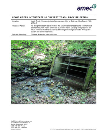
www.PDHcenter.comPDHonline Course C619Rounded on 3 edges to radius of [1/12(D)] orbeveled edges on 3 sideswww.PDHonline.org0.2Wingwalls at 30 to 75 to barrelSquare‐edged at crown0.4Crown edge rounded to radius of [1/12(D)]0.2Wingwalls at 10 or 25 to barrelSquare‐edged at crown0.5Wingwalls parallel (extension of sides)Square‐edged at crown0.7Side‐ or slope‐tapered inlet0.2Note: End Sections conforming to fill slope, made of either metal or concrete, are the sectionscommonly available from manufacturers. From limited hydraulic tests they are equivalent in operationto a headwall in both inlet and outlet control. Some end sections incorporating a closed taper in theirdesign have a superior hydraulic performance.Inlets With HeadwallsHeadwalls may be used for a variety of reasons:(1) increasing the efficiency of the inlet(2) providing embankment stability(3) providing embankment protection against erosion(4) providing protection from buoyancy or(5) to shorten the length of the required structure.The primary reasons for using headwalls are for embankment protection, buoyancy control, and ease ofmaintenance.Figure 1 shows typical headwall and wingwall configurations. Culvert or storm sewer headwallsconstructed in or adjacent to public right‐of‐way should be designed to protect pedestrians. Thisprotection should include a pipe railing fence on the headwall and any wingwalls, unless the grading andsize of the pipe precludes the need for the fence. 2013Jerry D. MorrowPage 12 of 63
www.PDHcenter.comPDHonline Course C619www.PDHonline.orgWingwalls And ApronsWingwalls are used where the side slopes of the channel adjacent to the entrance are unstable or wherethe culvert is skewed to the normal channel flow. Little increase in hydraulic efficiency is realized withthe use of wingwalls, regardless of the pipe material use and the use should be justified for otherreasons. Wingwalls can be used to increase hydraulic efficiency if designed as a side‐tapered inlet.If high headwater depths are to be encountered, or the approach velocity in the channel will causescour, a short channel apron should be provided at the toe of the headwall. This apron should extend atleast one pipe diameter upstream from the entrance, and the top of the apron should not protrudeabove the normal streambed elevation.Improved InletsWhere inlet conditions control the amount of flow that can pass through the culvert, improved inletscan greatly increase the hydraulic performance at the culvert. The design for this type of inlet isdescribed in the Design Of Improved Inlets. 2013Jerry D. MorrowPage 13 of 63
www.PDHcenter.comPDHonline Course C619www.PDHonline.orgFigure 1Typical Headwall and Wingwall ConfigurationsSource: Wright‐McLaughlin EngineersManning's n Values ‐ Table 3Type of ConduitWall & Joint DescriptionManning's nConcrete PipeGood joints, smooth walls0.011‐0.013Good joints, rough walls0.014‐0.016 2013Jerry D. MorrowPage 14 of 63
www.PDHcenter.comPDHonline Course C619www.PDHonline.orgPoor joints, rough walls0.016‐0.017Good joints, smooth finished walls0.014‐0.018Poor joints, rough, unfinished walls0.014‐0.0182 2/3 by 1/2‐inch corrugations0.027‐0.022Metal Pipes and6 by 1‐inch corrugations0.025‐0.022Boxes, Annular5 by 1‐inch corrugations0.026‐0.025Corrugations3 by 1‐inch corrugations0.028‐0.0276 by 2‐inch structural plate0.035‐0.0339 by 2 1/2‐inch structural plate0.037‐0.0332 2/3 by 1/2‐inch corrugated24‐inch plate width0.024‐0.0123/4 by 3/4‐inch recesses at 12‐inch spacing,good joints0.012‐0.013Concrete BoxCorrugatedCorrugatedMetal Pipes,Helical Corrugations,Full Circular FlowSpiral Rib Metal PipeNote: For further information concerning Manning n values for selected conduits, consult HydraulicDesign of Highway Culverts, Federal Highway Administration, HDS No. 5, page 163.Culvert SkewsNormally, culvert skews should not exceed 45 degrees as measured from a line perpendicular to theroadway centerline.Minimum Culvert SizeThe minimum culvert size should be 18 inches for roadways and 12 to 15 inches for driveways asspecified by jurisdictional agencies for the area.Outlet ProtectionIn general, scour holes at culvert outlets provide efficient energy dissipation. As such, outlet protectionfor the culvert should be provided where the outlet scour hole depth computations indicate: 2013Jerry D. MorrowPage 15 of 63
www.PDHcenter.com1.2.3.4.PDHonline Course C619www.PDHonline.orgthe scour hole will undermine the culvert outlet,the expected scour hole may cause costly property damage,the scour hole will cause a nuisance effect (most common in urban areas), orthe scour hole will conflict with land use.Permitting ConsiderationsThere may be federal or state permitting implications that affect the culvert design. These could includewetlands, regulatory floodplains and preparation of a storm water pollution prevention plan forconstruction activity.Safety ConsiderationsTraffic should be protected from culvert ends as follows:1. Small culverts should use an end section or a sloped headwall.2. Large culverts should receive one of the following treatments:a. Be extended to the appropriate "clear zone" distance per AASHTO Roadside Design Guide.b. Shielded with a traffic barrier if the culvert is very large, cannot be extended, or has a channelwhich cannot be safely traversed by a vehicle.3. Each site should be routinely inspected to determine if safety problems exist for traffic or for thestructural safety of the culvert and embankment.Loading RequirementsReinforced concrete box culverts, reinforced concrete pipe culverts, and corrugated metal pipe culvertsshould all be designed for HS20 live load, with the appropriate impact factor, and dead load. Dead load(fill) should be based on the depth of earth cover, plus pavement, above the top of the culvert.Culvert Flow Controls And EquationsGenerally, the hydraulic control in a culvert will be at the culvert outlet if the culvert is operating on amild slope. Entrance control usually occurs if the culvert is operating on a steep slope.For outlet control, the head losses due to tailwater and barrel friction are predominant in controlling theheadwater of the culvert. The entrance will allow the water to enter the culvert faster than thebackwater effects of the tailwater and barrel friction will allow it to flow through the culvert. 2013Jerry D. MorrowPage 16 of 63
www.PDHcenter.comPDHonline Course C619www.PDHonline.orgFor inlet control, the entrance characteristics of the culvert are such that the entrance head losses arepredominant in determining the headwater of the culvert. The barrel will carry water through theculvert more efficiently than the water can enter the culvert.Design procedures herein contained are for the design of culverts with a constant discharge, consideringinlet and outlet control.Inlet and Outlet ControlInlet Control ‐ If the culvert is operating on a steep slope it is likely that the entrance geometry willcontrol the headwater and the culvert will be designed on inlet control.Outlet Control ‐ If the culvert is operating on a mild slope, the outlet characteristics will probably controlthe flow and the culvert will be on outlet control.Proper culvert design and analysis requires checking for both inlet and outlet control to determinewhich will govern particular culvert designs. More information on inlet and outlet control can be foundin the Federal Highway Administration publication entitled Hydraulic Design Of Highway Culverts, HDS‐5,1985.EquationsThere are many combinations of conditions which classify a particular culvert's hydraulic operation. Byconsideration of a succession of parameters, the engineer may arrive at the appropriate calculationprocedure. The most common types of culvert operations for any barrel type are classified as follows.Mild SlopeCritical Depth ‐ Outlet Control ‐ The entrance is unsubmerged (HW 1.5D), the critical depth is less thanuniform depth at the design discharge (dc du) and the tailwater is less than or equal to critical depth(TW dc). This condition is a common occurrence where the natural channels are on flat grades andhave wide, flat floodplains. The control is critical depth at the outlet.HW dc Vc2/(2g) He Hf ‐ SL (Equation 1)Where: HW headwater depth (ft.)dc critical depth (ft.)Vc critical velocity 2013Jerry D. MorrowPage 17 of 63
www.PDHcenter.comPDHonline Course C619www.PDHonline.org2g 32.2 (ft./sec )He entrance headloss (ft.)Hf friction headloss (ft.)S slope of culvert (ft./ft.)L length of culvert (ft.)Tailwater Depth ‐ Outlet Control ‐ The entrance is unsubmerged (HW 1.5D), the critical depth is lessthan uniform depth at design discharge (dc du) and TW is greater than critical depth (TW dc) and TWis less than D.(TW D). This condition is a common occurrence where the channel is deep, narrow, and well defined.The control is tailwater at the culvert outlet. The outlet velocity is the discharge divided by the area offlow in the culvert at tailwater depth.HW TW V2/(2g) He Hf ‐ SL (Equation 2)Where:HW headwater depth (ft.)TW tailwater at the outlet (ft.)V velocity based on tailwater depth (ft.)g 32.2 (ft./sec2)He entrance headloss (ft.)Hf friction headloss (ft.)S slope of culvert (ft./ft.)L length of culvert (ft.)Tailwater Depth Barrel Depth ‐ Outlet Control ‐ This condition will exist if the critical depth is less thanuniform depth at the design discharge (dc du) and TW depth is greater than D (TW D) or; the criticaldepth is greater than the uniform depth at the design discharge (dc du) and TW is greater than (SL D), [TW (SL D)]. The HW may or may not be greater than 1.5D, though often it is greater. If thecritical depth of flow is determined to be greater than the barrel depth (only possible for rectangularculvert barrels), then this operation will govern. Outlet velocity is based on full flow at the outlet.HW H TW ‐ SL (Equation 3)Where: HW headwater depth (ft.) 2013Jerry D. MorrowPage 18 of 63
www.PDHcenter.comPDHonline Course C619www.PDHonline.orgH total head loss of discharge through culvert (ft.)TW tailwater depth (ft.)SL culvert slope times length of culvert (ft.)Tailwater Depth Barrel Depth ‐ Outlet Control ‐ The entrance is submerged (HW 1.5D) and thetailwater depth is less than D (TW D). Normally, the engineer should arrive at this type of operationonly after previous consideration of the operations depth covered when the critical depth, tailwaterdepth, or "slug" flow controls the flow in outlet control conditions.
www.PDHcenter.com PDHonline Course C619 www.PDHonline.org