Transcription
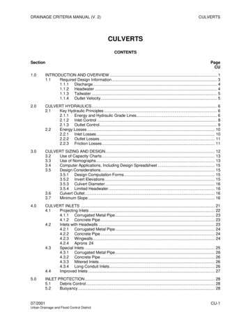
DRAINAGE CRITERIA MANUAL (V. TION AND OVERVIEW . 11.1Required Design Information . 31.1.1 Discharge. 41.1.2 Headwater . 41.1.3 Tailwater . 51.1.4 Outlet Velocity. 52.0CULVERT HYDRAULICS. 62.1Key Hydraulic Principles . 62.1.1 Energy and Hydraulic Grade Lines. 62.1.2 Inlet Control . 82.1.3 Outlet Control. 92.2Energy Losses . 102.2.1 Inlet Losses. 102.2.2 Outlet Losses. 112.2.3 Friction Losses. 113.0CULVERT SIZING AND DESIGN. 123.2Use of Capacity Charts. 133.3Use of Nomographs. 133.4Computer Applications, Including Design Spreadsheet . 153.5Design Considerations. 153.5.1 Design Computation Forms. 153.5.2 Invert Elevations . 153.5.3 Culvert Diameter. 163.5.4 Limited Headwater. 163.6Culvert Outlet. 163.7Minimum Slope . 164.0CULVERT INLETS . 214.1Projecting Inlets . 224.1.1 Corrugated Metal Pipe. 234.1.2 Concrete Pipe . 234.2Inlets with Headwalls . 234.2.1 Corrugated Metal Pipe. 244.2.2 Concrete Pipe . 244.2.3 Wingwalls. 244.2.4 Aprons 244.3Special Inlets . 254.3.1 Corrugated Metal Pipe. 264.3.2 Concrete Pipe . 264.3.3 Mitered Inlets . 264.3.4 Long Conduit Inlets. 264.4Improved Inlets . 275.0INLET PROTECTION . 285.1Debris Control . 285.2Buoyancy . 2807/2001Urban Drainage and Flood Control DistrictCU-1
CULVERTSDRAINAGE CRITERIA MANUAL (V. 2)6.0OUTLET PROTECTION . 306.1Local Scour . 306.2General Stream Degradation. 307.0GENERAL CONSIDERATIONS . 327.1Culvert Location. 327.2Sedimentation. 327.3Fish Passage . 337.4Open Channel Inlets . 337.5Transitions . 337.6Large Stormwater Inlets. 337.6.1 Gratings . 347.6.2 Openings . 347.6.3 Headwater . 347.7Culvert Replacements . 347.8Fencing for Public Safety. 348.0TRASH/SAFETY RACKS . 358.1Collapsible Gratings. 368.2Upstream Trash Collectors . 369.0DESIGN EXAMPLE . 379.1Culvert Under an Embankment . 3710.0CHECKLIST. 4311.0CAPACITY CHARTS AND NOMOGRAPHS. 4412.0REFERENCES . 58TablesTable CU-1—Inlet Coefficients For Outlet Control . 21FiguresFigure CU-1—Definition of Terms for Closed Conduit Flow. 6Figure CU-2—Definition of Terms for Open Channel Flow . 7Figure CU-3—Inlet Control—Unsubmerged Inlet . 8Figure CU-4—Inlet Control—Submerged Inlet . 9Figure CU-5—Outlet Control—Partially Full Conduit. 10Figure CU-6—Outlet Control—Full Conduit . 10Figure CU-7—Culvert Capacity Chart—Example. 17Figure CU-8—Design Computation for Culverts—Blank Form . 18Figure CU-9—Inlet Control Nomograph—Example. 19Figure CU-10—Outlet Control Nomograph—Example. 20Figure CU-11—Common Projecting Culvert Inlets. 22Figure CU-12—Inlet With Headwall and Wingwalls . 23Figure CU-13—Typical Headwall-Wingwall Configurations . 25Figure CU-14—Side-Tapered and Slope-Tapered Improved Inlets . 27CU-207/2001Urban Drainage and Flood Control District
DRAINAGE CRITERIA MANUAL (V. 2)CULVERTSFigure CU-15—Design Computation Form for Culverts—Example 9.1 . 39Figure CU-16—Headwater Depth for Concrete Pipe Culverts with Inlet Control—Example 9.1 . 40Figure CU-17—Head for Concrete Pipe Culverts Flowing Full (n 0.012)—Example 9.1. 41Figure CU-18—Culvert Capacity Standard Circular Corrugated Metal Pipe HeadwallEntrance 18” to 36” . 45Figure CU-19—Culvert Capacity Standard Circular Corrugated Metal Pipe HeadwallEntrance 36” to 66” . 46Figure CU-20—Culvert Capacity Standard Circular Corrugated Metal PipeProjecting Entrance 18” to 36” . 47Figure CU-21—Culvert Capacity Standard Circular Corrugated Metal PipeProjecting Entrance 36” to 66” . 48Figure CU-22—Culvert Capacity Circular Concrete Pipe Square-Edged Entrance 18” to 66” . 49Figure CU-23—Culvert Capacity Circular Concrete Pipe Square-Edged Entrance 60” to 180” . 50Figure CU-24—Culvert Capacity Circular Concrete Pipe Groove-Edged Entrance 18” to 66” . 51Figure CU-25—Culvert Capacity Circular Concrete Pipe Groove-Edged Entrance 60” to 180” . 52Figure CU-26—Headwater Depth for Corrugated Metal Pipe Culverts With Inlet Control . 53Figure CU-27—Headwater Depth for Concrete Pipe Culverts With Inlet Control . 54Figure CU-28—Headwater Depth for Circular Pipe Culverts With Beveled Ring Inlet Control . 55Figure CU-29—Head for Standard Corrugated Metal Pipe Culverts Flowing Full n 0.024 . 56Figure CU-30—Head for Concrete Pipe Culverts Flowing Full n 0.012 . 57PhotographsPhotograph CU-1—Public safety considerations for long culverts should be accountedfor with culvert designs such as with this collapsible trash rack at a park-like location. 2Photograph CU-2—Culverts can be designed to provide compatible upstreamconditions for desirable wetland growth. . 2Photograph CU-3—Culverts can be integrated into the urban landscape without negativevisual impact. . 2Photograph CU-4—Public safety features such as the rack at the entrance to an irrigationditch and the railing on the wingwalls must be considered. . 4Photograph CU-5—Energy dissipation and outlet protection are essential to promotechannel stability. . 31Photograph CU-6—Smal
Photograph CU-6—Small trash racks at culvert entrance will increase the risk of entrance plugging. . 35 07/2001 CU-3 Urban Drainage and Flood Control District . DRAINAGE CRITERIA MANUAL (V. 2) CULVERTS 1.0 INTRODUCTION AND OVERVIEW The function of a culvert is to convey surface water across a highway, railroad, or other embankment. In addition to the hydraulic function, the culvert
