Transcription
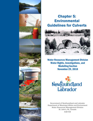
Chapter 5:EnvironmentalGuidelines for CulvertsWater Resources Management DivisionWater Rights, Investigations, andModelling SectionNovember 29, 2018Government of Newfoundland and LabradorDepartment of Municipal Affairs and EnvironmentWater Resources Management DivisionSt. John’s, NL, CanadaA1B 4J6
Chapter 5Environmental Guidelines ForCULVERTSWater Resources Management DivisionWater Rights, Investigations, and Modelling SectionNovember 29, 2018
5.0CULVERTSTable of ContentsPageList of Tables. iiiList of Figures . iii5.lGeneral . 15.2Culvert Location and Shape . 35.2.15.2.25.2.35.2.45.3Culvert Capacity . 65.3.15.3.25.3.35.3.45.3.55.4Provide Adequate Capacity to Prevent Surcharge . 6Allowance for Limited Gravel Deposition . 8Maintain Natural Stream Channel Capacity . 10Debris Control Structures and Culvert CapacityShould Address Maintenance Requirements . 10Anticipate Reduced Capacity . 10Flow Velocities in Culverts . 115.4.15.4.25.4.35.5Select a Stable Location . 4Select a Site With Uniform Channel Gradient. 4Location With Regard to Ice . 4Culvert Shape . 4Choose Design Velocities to Suit Existing Flow Conditions . 11Results of High Velocity . 11Choose Correct Gradient . 12Culvert Installation and Construction Practices . 125.5.15.5.25.5.35.5.45.5.5Installation to Manufacturer's Specifications . 13Operation of Heavy Equipment . 13Work During Times of Low Flow . 14Avoid In-Stream Excavation, Work in the Dry . 14Control of Stream Flow for Culvert Placement . 14-i-
ert Inlet and Outlet Structures . 165.6.15.6.25.6.35.6.45.6.55.6.65.6.75.7Culvert Gradient to Follow Stream Gradient . 14Multiple Culvert Installations. 14Place Culvert at Correct Elevation . 15Quality of Bedding and Backfill Material for Culverts . 15Procedure for Backfilling Culverts . 16Removal of Shipping Supports . 16Headwalls Required . 17Use of Armour Rock . 17Use of Slope-Tapered Inlets . 18Use of Steel End Sections . 18Use of Concrete . 18Trash Racks Should be Sloped. 18Use of Spill Aprons for Scour Protection . 19Inspection and Maintenance . 195.7.1 Inspect Culverts Regularly . 195.7.2 Inspect Culverts During and After Major Floods . 195.7.3 Establish a Culvert Maintenance Program. 195.7.4 Mark Culvert Inlets and Outlets for Identification . 195.7.5 Protect Inlets and Outlets . 195.7.6 Replace Damaged Culverts . 205.7.7 Maintenance Access . 20- ii -
5.0CULVERTSList of TablesPage5.1Transport velocity for various sizes of streambed materials . 12List of Figures5.15.25.35.45.55.65.75.85.9A Corrugated Steel Culvert Mitred to the Face of a Wall (Top),and a Small Plastic Culvert with a Masonry Headwall (Bottom) . 2Common Shapes for Corrugated Steel Culverts . 5Corrugated Steel Arch Culvert . 5California Balanced Design Method . 7Countersunk Culvert . 9Conversion of Normal Round Culvert to Countersink Size . 10Poorly Installed Culverts . 13Two Culverts with a Shared Outlet Location . 15Pipe Arch Culvert with Masonry Headwall and Wingwalls . 17- iii -
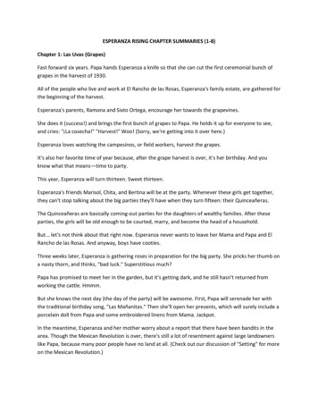
5.05.lCULVERTSGeneralCulverts are often used to provide access across drainage ditches, intermittent streamsand small watercourses. Culverts can provide an efficient and inexpensive means ofcrossing provided they are properly designed and properly installed at suitablelocations. Often culverts are also necessary to provide drainage where roads or otherstructures would interfere with the otherwise normal flow of surface runoff.Temporary or permanent culvert stream crossings are preferred to fording of smallwatercourses where extensive fording may give rise to channel destabilization.On some streams it is environmentally desirable to construct bridges instead ofculvert crossings because bridge installations can avoid extensive alteration of theflow regime which is inherent with most culvert installations. Bridges are alsopreferred to culverts in crossing all streams which support fish populations. Culvertinstallations usually result in more substantial alteration or loss of sections of thenatural channel bed and can cause a partial or total barrier to fish migration.Installation of culverts in major watercourses and rivers, instead of bridges, is notconsidered a good environmental practice.Many types of culverts are available from suppliers, the most popular beingcorrugated steel pipe. Reinforced concrete culverts, and plastic pipe culverts, areusually available in round sections only. Examples of corrugated steel and plasticculverts can be seen in Figure 5.1. Corrugated steel culverts are available in a largevariety of cross sectional shapes and sizes to suit varying stream conditions orrequirements, the most popular shape being round or arched.All culvert installations of significant size, including multiple or gang culvertinstallation, should undergo thorough hydraulic and hydrologic analysis. Factors suchas channel gradient, flow velocity, channel cross section, channel roughness,discharge patterns, peak water levels, quantity of flow, and ice formation must beconsidered.-1-
5.0CULVERTSFigure 5.1A Corrugated Steel Culvert Mitred to the Face of a Wall (Top), and aSmall Plastic Culvert with a Masonry Headwall (Bottom)-2-
5.0CULVERTSThe completed culvert installation should safely accommodate reasonably predictablelevels of flow and adequately resist the erosive action of moving water withoutcreating any adverse environmental impact at the crossing or in upstream ordownstream areas. Flow quantity may be predicted through a variety of methodsincluding the rational method, unit hydrograph, SCS Method, or Regional FloodFrequency Analysis. In addition to utilizing any of these methods a relevant amountof data must be collected on the stream and its watershed such as:-historical streamflowsvelocity distribution in streamhigh water marksice shove marksprecipitation datapotential river scour dataice formation and ice jamming areasrating of erosion hazardsurface drainage patternsfloodplainssurface area of rivers, lakes, bays, wetlandsWhile it is not always necessary or possible to determine all of the source data listedabove it is generally advisable to have sufficient data to check expected flood flow byat least two independent methods.The following sections of this chapter provide helpful information for culvert designand installation to ensure that the width and depth of flow expected in the streamunder natural conditions is not significantly altered by the installation of culverts.Construction procedures should follow these guidelines with the primary objectivebeing to prevent environmental damage such as pollution and siltation. Theseguidelines are intended to provide explanatory information and guiding principles butdo not provide a complete code for design because certain design criteria such as loadbearing capacity should be derived from appropriate texts. Engineering advice shouldbe sought by lay people who wish to purchase and install their own culverts.5.2Culvert Location and ShapeThe location of culverts is perhaps the most important consideration in installing anenvironmentally satisfactory culvert crossing. While the location of the road willprobably be the primary consideration, it is important to realize that minor changes inroad alignment may be necessary to avoid problem areas as far as culvert installationsare concerned.-3-
5.0CULVERTS5.2.1Select a Stable LocationAvoid locations where there are abrupt or short radius bends in the streamchannel and areas where erosion, undercutting, or fine soils are evident. Theseareas are often subject to greater erosive force which could create problemsfor a culvert installation.Heavy erosive action can lead to undercutting of the culvert and structuraldamage. In addition, these areas are often unstable and the channel may beshifting. If the stream bed is mobile it may eventually bypass the culvert,rendering the installation useless. Culvert crossings should be located onstraight, stable channel segments with no evidence of heavy erosive action.5.2.2Select a Site With Uniform Channel GradientSelect a culvert site where the channel gradient is uniform for a distanceupstream and downstream in the channel. This will avoid areas where theremay be sudden increases in water velocity immediately upstream ordownstream of the installation. The gradient must be constant at the crossingitself. Culverts should never be installed with bends in them.Steeper channel gradients result in higher flow velocity. This could mean thatthe installation would be subject to greater risk of erosion and washout causedby the momentum of water striking the culvert inlet area. Areas of lowgradient should therefore be given preference.5.2.3Location With Regard to IceA culvert should not be located where large quantities of solid sheet ice areformed upstream. During spring runoff such ice may break loose and blockthe culvert. Outlet areas of small pools or ponds should therefore not beculverted.5.2.4Culvert ShapeThe shape of a culvert should conform to the site conditions and to the flowregime at that location. While round culverts are the most popular, a variety ofshapes are available (see Figure 5.2). Design options are limited by flowcharacteristics and highway alignment. Where elevation is restricted thedesigner may select a shape which is horizontally elongated to produce thesame cross sectional area with less height.-4-
5.0Figure 5.2CULVERTSCommon Shapes for Corrugated Steel CulvertsAlthough an open bottom arch is shown in Figure 5.2, arch "culverts" can betreated as bridges and are discussed in Chapter 4, "Bridges". A photo of anarch culvert can be seen in Figure 5.3.Figure 5.3Corrugated Steel Arch Culvert-5-
5.0CULVERTSWider culverts result in lower flow velocity. At low flows wider culverts mayhave insufficient water depth to allow fish passage.Generally, arch shapes are useful to reduce the elevation of fill, but they aremore difficult to install. Elliptical shapes provide better low flowcharacteristics. Multiple barrels of the same size or different sizes may beeasier to install and conform to the stream shape, but these installations aregenerally less efficient
All culvert installations should be designed to safely accommodate peak flow volumes estimated for that section of channel during the expected life of the culvert. This means that the size or capacity of a culvert should be commensurate with its expected serviceability. For instance a culvert installed under an infrequently used