Transcription
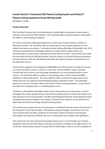
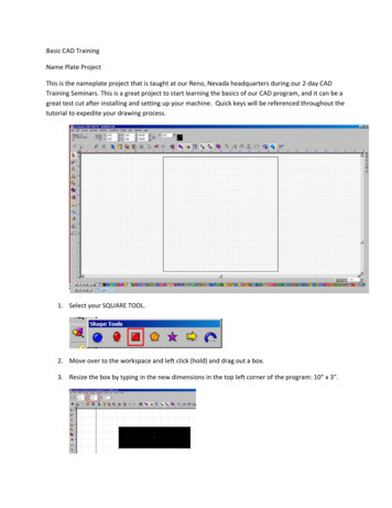
Basic CAD TrainingName Plate ProjectThis is the nameplate project that is taught at our Reno, Nevada headquarters during our 2-day CADTraining Seminars. This is a great project to start learning the basics of our CAD program, and it can be agreat test cut after installing and setting up your machine. Quick keys will be referenced throughout thetutorial to expedite your drawing process.1. Select your SQUARE TOOL.2. Move over to the workspace and left click (hold) and drag out a box.3. Resize the box by typing in the new dimensions in the top left corner of the program: 10” x 3”.
4.Once the box is created and resized, use the TEXT TOOL to type your name.Select the TEXT TOOL.5. Once the text tool is selected, the cursor with change from a normal pointer to a white pointerwith a “T”. Left click above the box to initialize the text tool.6. Now select the “F” button displayed at the top.This will bring up the FONT DETECTIVE.
The FONT DETECTIVE allows you to go through all of your fonts and select the one you want to use. Pickyour desired FONT and press SELECT. This will close the dialog box, allowing you to type in your name.and go to ARRANGE/TEXT TO GRAPHICS. This will7. Now select your Orange Pointer toolconvert the text that you generated into an OBJECT. Then click ARRANGE/MAKE PATH. This willkeep the text in one piece.
8.Once it is placed in the position that you want, select all (ctrl A), then go to ARRANGE/MAKEPATH. Turn on VIEW/SHOW FILL (alt S).9.The fill shows what will drop out and what will stay behind, so we can see that the “A” and the“P” will require a connection from the main letters to the “floating” pieces. These are what wecall bridges.10. Bridges can be any shape, but in this example we will use the basic rectangle.Select your rectangle tool.Generate a rectangle and make it .20” wide by 1” tall.
11. Now we will create three of them by having your item selected and pressing (ctrl D) x2 forDUPLICATE .12. Select one and move it to the first area you need bridged. Notice that when you have the itemselected an arrow appears in the top right hand corner, this allows you to rotate your object.You can use the arrow keys on the keyboard to fit it into a better position.This is what it should look like once all of the bridges are in place.
You can see that the bridges anchor the parts that would have previously dropped out. You canalter the size of these to fit your individual name.13. Once all the bridges are in place, you will SELECT ALL (ctrl A), and then select the BASIC WELDto weld them into place.
14. Now that everything is welded into place, it’s time to generate the legs for the name plate. Wewill generate these with the rectange tool. Configure the dimensions to be: 0.5” wide by 1.75”tall.15. Select the Orange pointer tool and press DUPLICATE (ctrl D) x2. We will then select one of therectangles and move it to the bottom-right side of the nameplate. Space out the otherrectangles appropriately, as displayed below.16. Select the right leg and press and hold SHIFT and select the nameplate. This will select just theright leg and the name plate. Press “R”. This will align the leg you have selected to the RIGHT.
17. Select the center leg, hold shift and select the nameplate. Press “C” for CENTER.18. Select the left leg, hold shift and select the name plate. Press “L” for LEFT19. Now we are going to select all three legs and press “E” for EVEN. This will vertically even out theobjects selected.
20. Now that the legs are all selected, use the arrow keys to move the legs to overlap the base ofthe nameplate.
21. Now select all (ctrl A) and do your BASIC WELD. This will weld the legs to the nameplate.22. Now we need to generate the cross brace for the legs. Select the Rectangle tool and draw out arectangle. Size the dimensions to: 10” wide and .5” tall.23. In order to place this bottom bar, select all (ctrl A) and press “C” (center) and “B” (bottom).
24. Now go to your Weld Tool and select BASIC WELD.25. Time for the tool path. Select all (ctrl A) and go to MACHINE/CREATE TOOL PATH/MALE
This will bring up the MALE TOOL PATH dialog. We will skip the TEMPLATES TAB and go to BASICCUT tab.Make sure that your tool is set for PLASMA. Select your direction to CLIMBING. Enter in yourFEED RATE to be 100. Now go to the LEAD IN/OUT tab.
Lead-ins can be a LINE or an ARC. What you are cutting usually determines the type of lead-inyou are generating. For this project, because we have TEXT, we are going to select the ARC leadin so the lead-in takes up less space. Once you press “OK,” the tool path will be applied.
26. Once the tool path is applied we will then do a Select All (ctrl a) and put the design in the X-0,Y-0 coordinates (bottom left corner of the workspace).27. Now we need to generate the G-CODE file for the VMD (Visual Machine Designer. Go toMACHINE/OUTPUT.28. Once the OUTPUT opens, it will show you the tool path. On the CUT TOOLBOX bar you will pressthe Numerical Control Manager. This will generate your G-CODE for the VMD software.
29. Once the G-Code is created, save the file to the location of your choice. Press the scissors on theend of the CUT TOOL bar. This will bring up a SAVE dialog box. Save your file as NAMEPLATE.GM.
30. Close the OUTPUT CONTROL tool bar.31. Go to FILE/SAVE AS, and save your file as NAMEPLATE.CDL. This format will allow you to alterthe CAD drawing if you need to change something in the future.This completes the NAMEPLATE project.
Hot Keys Used.MAKE PATH(ctrl H)SHOW FILL(alt S)DUPLICATE(ctrl D)Alignment when two objects are en(E)
Basic CAD Training . Name Plate Project . This is the namep late project that is taught at our Reno, Nevada headquarters during our 2-day CAD Training Seminars. This is a great project to start learning the basics of our CAD program, and it can be a great test cut after installing and setting up your machine.