Transcription
Computer Aided Drafting(CAD) StandardsFacilities Planning and ConstructionOCTOBER 2020
University of Nebraska CAD StandardsTable of Contents12Introduction .31.1The Need for (CAD) Standards .31.2Building Information Modeling (BIM) .31.3Standard of Production .3CAD Drawing Setup Process .42.1CAD Drawing File Format .42.2Sheet Numbering and File Identification .42.2.1Sheet Numbering .42.2.2File Identification .42.2.3Alternate File Identification .42.33Drawing Environment .52.3.1External Reference & Imported Image Files .52.3.2Model Space and Paper Space .5CAD Parameters .63.1Units and Tolerances .63.1.1Units of Measure .63.1.2Tolerances .63.1.3Scale Factors .63.1.4Scale Factor and Text Table .63.2Drawing .73.2.1Drawing Description .73.2.2Drawing Walls .73.3Room, Space and Area .83.3.13.4Polylines and Room Square Footage .8Text .83.4.1Text Descriptions.83.4.2Text Style, Font and Size Table .93.5Dimensioning. 103.5.1Dimension Description . 103.5.2Dimension Style Parameters . 103.6Blocks, Details and Title Blocks . 113.6.1Block Definitions . 113.6.2NU FPC Defined Blocks and Details . 123.6.3Vendor Defined Blocks and Symbols . 123.6.4NUTitle Blocks . 121
University of Nebraska CAD Standards3.6.5NU Symbols . 123.6.6Addenda, Revisions . 123.7Layers . 133.7.1Layer Description . 133.7.2AIA CAD Layer Naming Summary . 133.7.3NU FPC Layer Properties. 163.7.4NU FPC Layer Property Table . 163.7.5Layer Attributes . 223.7.6Layer Colors . 223.7.7Layer Linetypes . 223.7.8Layer Lineweight . 224CAD Templates . 235NU Space & Door Numbering Requirements . 23675.1Room, Space & Area Numbering . 235.2Door Numbering . 235.3Signage . 23CAD Reproduction. 236.1NU Drawing File Disclaimer . 236.2Plot Styles . 246.3NU FPC Color and Line Weights . 246.4Printing . 246.5Sheet Size . 256.6Delivery . 256.7Reproduction Quality Assurance. 26CAD Project Closeout Documentation . 277.1Reference Binding . 277.2Conversions and CAD Translations . 277.3As-Built Documents . 277.4Construction Revisions . 277.5Delivery . 287.6Waiver Procedure . 282
University of Nebraska CAD Standards1 Introduction1.1 The Need for (CAD) StandardsThe University of Nebraska Facilities Planning and Construction Department (NU FPC) is responsible forarchiving electronic “as-built” construction documents produced as part of capital construction projects.NU FPC is also responsible for generating and maintaining accurate electronic floor plans for all campusfacilities. These floor plans support many campus entities and initiatives including telecommunications,building automation systems, CCTV, access control, maintenance management, security, SpaceManagement (and Geographic Information Systems (GIS).In addition, NU FPC staff performs Architectural/Engineering design services on an in-house basis forsome capital construction projects.In order to support NU FPC’s missions, a well-defined and detailed set of Computer Aided Design (CAD)standards are required in order to maximize efficiencies and usability.This document details NU FPC’s CAD standards for the production and delivery of CAD documents for allcapital construction projects.1.2 Building Information Modeling (BIM)Refer to the BIM guidelines in the University design guidelines and provide as necessary per requirements.NU has adopted BIM as a process for recording project documentation, development and as-built recorddocumentation for select projects. Our goal is to achieve the following benefits form BIM.1.3 Standard of ProductionThe intent for the standard production of drawings and plans is to allow a multitude of personnel to review,revise, share, maintain and print various archived projects which all have similar parameters. Theseparameters include: Layering and colors Scale factors, line types and line weights Font type and size Room and door numbering Title block and sheet titles Drawing sequence and sheet numbers Model/Paper space and external reference files (Xrefs)FPC has adopted the latest version of the AIA CAD Guidelines found in the United States National CADStandard. All layer names and descriptions shall follow these standards. Some layer attributes in the AIACAD Guidelines have been predefined by NU FPC with set Colors, Linetypes and specific layer names inorder to maximize the printed clarity of archived drawings and to conform to core layer line weight/colorassignments. It is required that all vendors providing CAD documents to the University adopt the AIA CADGuidelines as well as implement the predefined layer attributes described herein.3
University of Nebraska CAD Standards2 CAD Drawing Setup Process2.1 CAD Drawing File FormatNU FPC require that vendors submit the most current version of AutoCAD .dwg formatted CAD files for allcapital construction intermediate design submittals and final “as-built” documents that are fully compliantwith all of the standards outlined herein, and which have no significant loss of drawing entities or projectdata that can result from standard CAD file translation procedures. PDF and DXF files will not be acceptedat project closeout as a substitution for “.dwg” CAD file deliverables only as supplemental information.All CAD files submitted shall be in the latest addition of Autodesk AutoCAD .dwg format.2.2 Sheet Numbering and File Identification2.2.1Sheet NumberingThe drawing/project sheet number for all projects must follow the single or double discipline, uppercasealphabetic designator followed by a three digit numerical sheet number with a dot, no spaces. The threedigit numerical number and dot can be used in any fashion at the discretion of the coordinating professionaland shall be similarly repeated by all disciplines. The numbers shall be arranged and used on a project byproject basis as it pertains to the size and complexity of a project, the number of floors, constructionphases, etc. A single or double digit number or sheet number not using a dot is unacceptable (i.e. A100;A01 or A4). A building name, acronym, project title or progress phase shall not be included in any way aspart of the sheet numbering. Below is an example of the NU FPC sheet numbering nomenclature required:“G0.01” or “A1.00” or “MD2.10” or “FP3.30”, etc.The first digit represents the discipline designator (G – General Sheet) (A – Architectural Sheets) (MD –Mechanical Demolition Sheets) (FP – Fire Protection Sheets) etc. Followed by a three digit numericalsheet number with a dot, no spaces (0.01) (1.00) (2.10) (3.30) etc. which is determined by the coordinatingprofessional based on the project complexity/parameters and similarly followed by all other disciplines.2.2.2File IdentificationThe drawing/project file name for all projects must be represented with the NU project number anddrawing/project sheet number. Each CAD, PDF or Revit drawing file shall be preceded with theNUproject number followed by a hyphen and then the drawing sheet number (as described previously) withno spaces. Finally, a last dot and then the file extension shall conclude the complete file naming. Abuilding name, acronym, project title or progress phase shall not be included in any way as part of the filenaming. Below is an example of the NU FPC file naming nomenclature:“467123-A1.01.dwg” or “467123-SD2.01.pdf”The first digits represent the NU project number (467123), then the hyphen as a placeholder to help makethe name more readable and easier to manage, followed by the sheet number (A1.01) (SD2.01). Thesheet number includes the discipline designator (A – Architectural) in this case a single digit used forArchitectural but expandable up to two alphabetical characters as indicated for (SD – StructuralDemolition). Next a three digit numerical sheet number with a dot, no spaces and finally the dot file nameextension (.dwg – AutoCAD file) (.pdf – Adobe System File).2.2.3Alternate File IdentificationIn some cases grouped PDF files, external CAD references/images, zipped files or Revit models mayrequire an alternate nomenclature. Each PDF, CAD, ZIP or Revit drawing file shall be preceded with the4
University of Nebraska CAD StandardsNU project number followed by a hyphen, then must follow the single or double discipline, uppercasealphabetic designator as deemed appropriate followed by a dot and the grouped file name, external CADreference description or short Revit Model description, no spaces. A building name, acronym, project titleor progress phase shall not be included in any way as part of the file naming. Variations of acceptable filenaming nomenclature for these type of files are indicated below:“467123-AE.binder.pdf” or “467123-ME.binder.pdf” or “467123-X.firstfloor.dwg” or “467123-A.binder.zip” or“467123-AE.model.rvt”The first digits represent the NU project number (467123), then the hyphen as a placeholder to help makethe name more readable and easier to manage, followed by the file name (AE.binder) (ME.binder)(X.firstfloor) (A.binder) (AE.model). The file name includes a single or double digit discipline designator asdeemed appropriate (AE all Arch/Eng. sheets in one file) (ME Mechanical Electrical sheets) (X AutoCAD external reference file) (A Architectural sheets). Finally the dot and a file name extension (.pdf– Adobe System file) (.dwg – AutoCAD file) (.zip – Zipped file) (.rvt – Revit file).2.3 Drawing Environment2.3.1External Reference & Imported Image FilesAll drawing floor plans shall be set up for shared use with external reference files (xrefs). Xrefs must beinserted into sheet files as an attachment or overlay using relative path method in lieu of the full pathmethod. Relative path allows drawings to be moved between subdirectories and still maintain their xreflinks. Full path (absolute) xref’s are not allowed. NU FPC encourages that any imported image files suchas JPG’s, Tiff’s, BMP’s, PDF’s, etc. used within a CAD drawing also be imported in the same manner andwith the same requirements as drawing xrefs.The base point for all drawing floor plans shall be set in model space at 0,0,0 reference point. Likewise, alldrawing floor plan xrefs inserted into a drawing shall be set in model space at 0,0,0 reference point. Thishelps to provide for a consistent insertion placement point from file to file.Sheet title blocks shall be inserted as an xref into paper space at 0,0,0 reference point. Title block sheetidentification names and sheet page numbers shall not be part of the xref and shall be editable from sheetto sheet. Title block sheet project information text shall be part of the xref and shall not be editable fromsheet to sheet. NU FPC requires that all vendors utilize the standard University of Nebraska title blocks,available for download in the CAD library download section. Refer to Blocks, Details and Title Blockssection herein for additional information.Upon project completion and prior to delivery to NU FPC all external reference files that were used duringCAD production shall be bound, inserted and retained as a block within a single drawing file, this includesthe title block and any image files. NU FPC will not accept the submission of any CAD drawings thatcontain external reference files.2.3.2Model Space and Paper SpaceAll submitted CAD file drawings shall contain only one variation of the floor plan and site plan in modelspace. Multiple enlarged partial plans, sections, elevations, details, schedules, dimensions, notes and othermaterial directly related to the drawing set shall also be completed in model space. Model space shall notcontain any alternate design considerations, collaboration ideas, multiple variations of design and otherwork that is not needed or not meant to be submitted as part of the construction documentation.Paper space is reserved to be used for viewports, title block and sheet titling information only. Multiplepaper space tab views, each with its own set of viewports, title block and sheet titling information isacceptable. Each tab view shall be named with the exact respective individual sheet number of depictedsheet. Tab view number and respective sheet number shall strictly follow NU FPC sheet numberingnomenclature.5
University of Nebraska CAD StandardsEach paper space tab view in a single drawing file is reserved for viewports depicting the elements of thatparticular floor, space or area. Multiple floor plan levels, (i.e. basement, first floor, second floor, etc.) shallbe laid out and provided in separate drawing files. NU FPC will not accept multiple floor levels within onesingle drawing file. Limit paper space layouts to only those sheets being submitted as part of theconstruction documentation.3 CAD Parameters3.1 Units and Tolerances3.1.1Units of MeasureAll CAD drawings shall be drawn in architectural units of feet and inches with a precision not less than1/64”. The format, precision and other conventions to be used in displaying coordinates, distances andangles are set and saved in the drawing units. This system of measure also pertains to the drawinggeometry and appropriate distance values required when dimensioning.3.1.2TolerancesBuilding floor plans, elevations, details and sections shall be shown at not less than 1/16” 1’-0” scale andno more than 1/2” 1’-0” drawings scale. Enlarged partial floor plans, sections and details shall be viewedat not less than 1/4" 1’-0” and no more than 3/4" 1’-0” drawing scale. Details, schedules and risers areacceptable to be viewed with no particular drawing scale. In these instances the text height of non-scaledentities shall follow the guidelines set forth in the text styles, heights and fonts sections. Whencircumstances warrant the use of alternate desired drawing scales the vendor shall request a variancethrough the NU FPC Project Manager or representative prior to design.3.1.3Scale FactorsAll CAD model space drawings shall be drawn at full scale. For example when drawing a door in CAD, thedoor should be drawn 3 feet wide and 7 feet tall.Model space layouts shall be inserted into paper space via viewports as described previously. Viewportswithin paper space are required to be scaled to fit the actual sheet size. To do this, a scale factor isrequired so that the final printed or viewed drawing sheet has a usable scale reference. Below is a quickreference guide for standard architectural scale factors to be used in scaling up or down and as a referencefor text size associated with the respective scale of the drawing or viewport.3.1.4Scale Factor and Text TableDrawing Scale1/16" 1'-0"3/32" 1'-0"1/8" 1'-0"3/16" 1'-0"1/4" 1'-0"3/8" 1'-0"Scale Factor Scale 1660.0156250.02083330.03125ViewportScaleDecimal Scale1/192xp1/128xp1/96xp1/64xp1/48xp1/32xp.0625" 1'-0".09375" 1'-0".125" 1'-0".1875" 1'-0".25" 1'-0".375" 1'-0"ModelPaperSpace Text Space �6”3/32”4.5”3/32”3”3/32”6
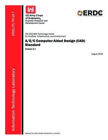
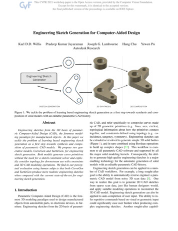
University of Nebraska CAD Standards1/2" 1'-0"240.01416661/24xp.50" 1'-0"3/4" 1'-0"160.06251/16xp.75" 1'-0"1" 1'-0"120.083331/12xp1" 1'-0"1 1/2" 1'-0"80.1251/8xp1.5" 1'-0"3" 1'-0"40.251/4xp3" 1'-0"1” 10’120.008331/120xp1” 10’1” 20’240.004171/240xp1” 20’1” 30’360.002781/360xp1” 30’1” 40’480.002081/480xp1” 40’1” 50’600.001671/600xp1” 50’1” 60’720.001391/720xp1” 60’1” 100’1200.000831/1200xp1” 100’All general drawing plan text size shall print out with a minimum height of 2 Drawing3.2.1Drawing DescriptionAll drawing plan layout entities including but not limited to details, diagrams, hatch patterns, wall types,symbols, line types, text and other predefined entities are strictly required to be created in the correct NUFPC standard layers and with bylayer properties. All predefined entities shall revert to layer 0 or bylayerproperties when exploded. All predefined entities created in programs other than AutoCAD shall alsorevert to bylayer properties. NU FPC requires the use of bylayer properties in order to swiftly and easilyconvert misused vendor layers and colors to the required NU standard layer and layer properties. Thestandard NU layer properties are essential to internal reproduction of plans from department to departmentwithout the need for storing and managing vendor plot styles.Similarly blocks, symbols and details shall also be created with bylayer properties and revert to layer 0 orbylayer properties when exploded. Refer to the Blocks and Details section herein for additional informationon the use and insertion of blocks within floor plans, drawings and/or xrefs.3.2.2Drawing WallsAll walls and elements of wall construction shall be clean and clear of erroneous additional lines, doublelines, fillers, hatch patterns, etc. which depict drywall, vapor barriers, insulation, air gaps, etc. Wallintersections shall be shown as actual intersections with lines terminating and/or ACAD fillet withintersecting wall line so that it is also clean and clear of erroneous lines, double lines, fillers, hatch patterns,etc. NU FPC archived drawings require walls be shown with only two lines, depicting the outer mostextents of walls. In the event that multiple lines are required to be shown on construction drawings todepict the various construction materials of the wall then the outer most lines of the drawn wall shall be onlayer A-WALL and all other lines labeled with an alternate layer name so that erroneous lines not relevantto NU can be easily frozen or isolated and erased upon delivery of drawing file to NU FPC. Refer to theexamples below for the properly drawn wall detail as it relates to NU archived drawing requirements.7
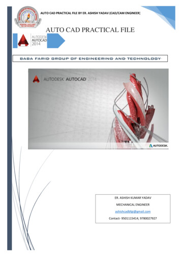
University of Nebraska CAD Standards3.3 Room, Space and Area3.3.1Polylines and Room Square FootageEach room, space, area, and general circulation space such as lobbies, corridors, vestibules, stairs andmezzanines shall be individually enclosed by a continuously joined polyline. The Polyline and squarefootage number associated with these individual space polylines shall be included in the space on theplans and provided on the appropriate layer and in the text style, font and size as listed in the text tableherein this document.The space polyline and area square footage numbers associated with individual rooms, spaces and areaas previously described shall be included on the AutoCAD .dwg plans. This procedure is similar to theprocess created with using BIM models. When a BIM model is used the polyline process shall be exportedfrom Revit as part of the AutoCAD export feature. When exporting Revit to AutoCAD in sessionexport setup click the Modify Export Setup button then select the General tab. Under the General tabcheck the Room and Area Boundaries box to Export Rooms and Areas as Polylines.3.4 Text3.4.1Text DescriptionsNU FPC requires that all text associated with the drawing of building floor plans, elevations, enlarged floorplans, section, details, schedules, risers, notes, call-outs, dimensions and titles be represented a standardNUtext style and font as indicated in the table below. All model text heights shown (unless notedotherwise) represent a model space layout drawn at 1/8” 1’-0” scale. Refer to the afore mentioned scalefactor section for conversion of model space text height per respective scale factor.8
University of Nebraska CAD Standards3.4.2Text Style, Font and Size TableUseText StyleFontModel PaperWidth Space SpaceHeight HeightAngleColorOrientationRoom,Space-Dwg TextArial1.01’-0”1/8”18White 790 Name/No.Door No. NU-Dwg TextArial1.01’-2”9/64”0White 70 or 90 Area SFNU-Dwg TextArial1.01’-6”3/16”18White 790 Dimensions NU-Dim TextArial1.09”3/32”0White 70 or 90 Leader Note NU-Dwg TextArial1.09”3/32”0White 70 GeneralNU-Dwg TextArial1.09”3/32”0White 70 NoteKeyed Note NU-Dwg TextArial1.09”3/32”0White 70 Equip. Tag NU-Dwg TextArial.99”3/32”0White 70 or 90 DemolitionNU-Dwg TextArial1.09”3/32”0White 70 TextExisting to145, 155 orNU-Dwg TextArial1.09”3/32”00 Remain Text163Gen. SingleNU-Dwg TextArial1.09”3/32”0White 70 or 90 Line TextElevation/Detail/NU-Dwg TextArial1.09”3/32”0White 70 Section TextRiser Text NU-Dwg TextArial1.09”3/32”0White 70 or 90 Note Titles NU-Dwg TextArial1.01’-0”1/8”0White 70 ScheduleNU-Dwg TextArial1.01’-0”1/8”0Red 10 TitlesElevation/Detail/NU-Dwg TextArial1.02’-0”1/4”0Red 10 SectionTitlesPlan &NU-Dwg TextArial1.02’-0”1/4”0Red 10 Sheet TitlesTitle BlockNU-Dwg TextArial1.0--1/8”0White 70 General InfoTitle BlockSheet Title & NU-Dwg TextArial1.0--3/16”0White 70 Projct.NameTitle BlockNU-Dwg TextArial1.0--3/8”0White 70 Sheet NumbAll model space text sizes above are listed at 1/8” 1’-0” for reference, actual text sizes to be adjustedaccording to respective scale factors. Only the above text style, sizes and fonts are approved by NU FPC,no frame, fill or non-standard AutoCAD text shall be used. Alternate styles, sizes and fonts must haveprior approval by NU FPC.9
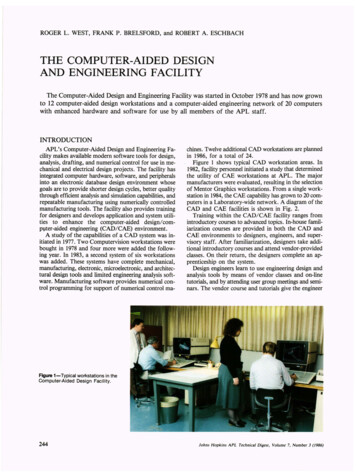
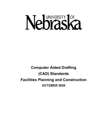
University of Nebraska CAD Standards3.5 Dimensioning3.5.1Dimension DescriptionAll dimensioning shall be completed in model space. Dimensioning shall also be completed in layer AANNO-DIMS, bylayer, white (7), continuous linetype and default lineweight. NU does not recognize theuse of Interior (I) discipline designator layers for dimensions and request that this either not be used whenat all possible or be converted to A-ANNO-DIMS layer upon output to AutoCAD .dwg delivery to NU FPC.3.5.2Dimension Style ParametersNU FPC suggests the use of the standard NU FPC dimension style. “NU-DIM” dimension style is availablefor download with the drawing title block templates found in the CAD library downloads section. NU-DIMstyle parameters shall be set according to the NU FPC standard dimension styles shown below: AlternateDimension Style Units are not defined therefore the Dialog Box is not displayed.10
University of Nebraska CAD Standards3.63.6.1Blocks, Details and Title BlocksBlock DefinitionsAll parameters of a CAD drawing including blocks, details, symbols and any other predefined entities shallbe easily modified. Floor plans, backgrounds, blocks, details, symbols and other predefined entities shallbe easily manipulated to match the NUFPC uniform standard layer and layer color assignments for bestviewing and plotting.All blocks, block definitions, details, hatch patterns, walls types, symbols, line types and other predefinedentities including block attributes shall be created in layer 0 with bylayer properties. All predefined blockentities shall revert to layer 0 and Bylayer properti
In order to support NU FPC’s missions, a well-defined and detailed set of Computer Aided Design (CAD) standards are required in order to maximize efficiencies and usability. This document details NU FPC’s CAD standards