Transcription
AUTO CAD PRACTICAL FILE BY ER. ASHISH YADAV (CAD/CAM ENGINEER)AUTO CAD PRACTICAL FILEER. ASHISH KUMAR YADAVMECHANICAL ENGINEERashishcadbfgi@gmail.comContact- 9501115414, 9780027927ASHISH
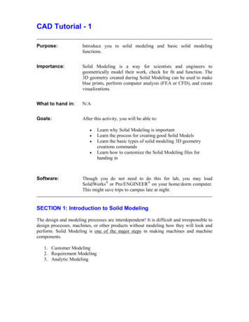
BABA FARID GROUP OF ENGINERING AND TECHNOLOGY(AUTO CAD 2014 FOR CIVIL, ELECTRONICS AND MECHANCIAL ENGINEERING)INTRODUCTION OF THE AUTO CAD SOFTWARE AND ITS UTILITIES IN THE ENGINEERING SOFTWARE.AutoCAD is a commercial software application for 2D and isometric and 3D computer-aideddesign (CAD) and Drafting software available since 1982 as a desktop application andsince2010 as a mobile web- cloud based app market as AutoCAD 360. This software isdeveloped and marketed by the Autodesk Company. AutoCAD is used across a wide range of industries, byarchitects, project managers, engineers, designers and other professionals.1. You can install the software package of AutoCAD through DVD and also AutoCAD LT version is also availablefor the beginners.2. Choose start All Programs Autodesk AutoCAD 2014You can also double click AutoCAD 2014 icon on your Windows Desktop.RIBBONDrawing areaUCS (USER CO-ORDINTATE SYSTEMCommand windowStatus bar1
BABA FARID GROUP OF ENGINERING AND TECHNOLOGYADVANTAGES OF THE AUTO CAD1. It has ability to producing very accurate designs. And drawing can be created in 2D or 3D .2. Easy to modify- modifying the CAD geometry is easy; you will always have “copy” “cut” paste and delete andmove or some similar editing option available with each of the package.3. Easy to Reproduce- Draftsmen used to take days to complete a drawing by manual drafting, and reproducingthe drawing means recreating the drawing from the beginning. But, in case of the CAD, you can reproducethe drawing in no time and makes as many copies as you can.4. Computer aided manufacturing- The 3D CAD geometry is used as input for the CAM packages for generatesNC codes. The manual drawings cannot be used for CAM packages.5. Environmental Friendly – Manual drawings are necessarily created on the paper, but the CAD drawings canbe stored and used electronically without using paper.6. Access Control – some of the drawings and design documents are very crucial for a company business, andsuch drawings should not be accessible to all. Providing are easy for the CAD drawings. Strict access controland maintaining confidentiality is difficult in manual drawing.STUDY THE BASIC INITIAL SETTING AND VIEWING OF THE DRAFTING SOFTWARE INTERFACE.HOW TO SET UNITS1. In autoCAD every object is measured in units. You determine the value of unit before you draw. For example,in one drawing, a unit might equal one millimeter of the real world object. In another drawing, a unit mightequal to inch. You can set the unit type and number of the decimal place for the object length and angles.COMMAND- UNITSor unUNIT FORMATEXAMPLESSCIENTIFIC1.55E 1’-3 ½”2
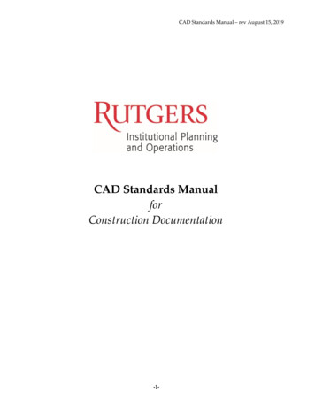
BABA FARID GROUP OF ENGINERING AND TECHNOLOGYUNITS In units settings go to “Type” choose the desired unit standard e.g. 0.000 for the decimal, 1E3 (1000)for the Engineering etc.In “Precision” choose the desired preciseness you need in the drawing e.g. 1.001 for (0.000) and for0.1 choose 0.0 and for 1 choose “0”Choose the insertion scale of your set perimeter or dimension e.g. millimeters, centimeters, inches,feet etc.Choose the angle type same as your desired units choose before e.g. decimal degrees, engineering,architectural etc.Click on “OK” to set the units and hit the Esc key to get out of the command.How to set the limits in Auto cadLIMITS in the rectangle boundary area in the AutoCAD where we draw our working drawings. Settingof the limits is the most important task because of in very large scale of drawing we need the actuallimits of the drawings so that they can easily printable and zoom and easy to the find the object wecreate in specified limit. type – LIMITS1. Specify the lower left corner of thescreen type (0,0) and hit the ENTER key2. Specify the Upper right corner of thescreen type (500,500) and hit the Enterkey. 500 is the specified units distancee.g. if you choose millimeters then 500mm 500mm is considered as a base height.3. Click the ZOOM tool in the status bar and type AORType ZAor DOUBLE CLICK on the mid mouse button.UPPER RIGHT CORNERLOWER LEFT CORNER3
BABA FARID GROUP OF ENGINERING AND TECHNOLOGYHOW TO SET THE DRAFTING SETTINGS IN THE AUTOCADDSETTINGS – TOOLS DRAFTING SETTINGS Drafting settings this dialogue box contain so many tabs like Snap and Grid, Polar tracking, Object snap, DynamicInput etc. let discuss each tab one by oneRight click on the status bar and choose properties thedrafting setting box will appears to you in the AutoCADscreen.Command – DSETTINGS1. Object snap (F3) - it’s used to turns the running snap onand off when the object snap is on it will shows the mainsnap points of the object which is relative to the otherobject e.g. end point, midpoint, center point, tangentpoint, perpendicular etc.2. Object Snap tracking (F11)- object snap tracking gives the tracking point of the object near to the relativepoint of the another object which is more helpful and no need to draw any extra helping line to follow theobject corner, center, quadrant tracking.3. Dynamic input (F12) - The dynamic input enables the graphics cursor with the power of the command line.Thus you enter dimensional and command option information as you work, you get immediate feedbackwhen your dynamic input is ON.4. Snap (F7) and Grid (F9)- Snap and Grid mode is used for the showing the graphical representation and whenwe move the mouse cursor it will not move freely it will move point to point as we set the graph snap point.e.g. if we set snap 0.5 to 0.5 the mouse corsur move to the distance .5 on the computer screen.5. ORTHO MODE (F8) – Ortho mode is used to draw a straight line if we need to draw a perfect straight line youneed to on the ortho mode by pressing F8 button on your keyboard.6. POLAR TRACKING (F10)- Polar tracking is used when we work on the specified angel it will automaticallytracks the angel we choose and indicate us with green hidden line indication. You can also choose yourcostum angle by click on the additional angle New and put the specified angle you need.4
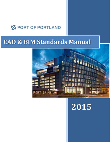
BABA FARID GROUP OF ENGINERING AND TECHNOLOGYVARIOUS TYPE OF CO-ORDINATE SYSTEM USED IN AUTO CADAll the drawings are suprimposed on an invisible grid, or co-ordinate system with Horizontal axis and Verticalaxis which is commonly known as X axis and Y axis.Y axisX axisIn AutoCAD there are main three types of CO-ORDINATE system used. Each of the co-ordinate are explained follows.Absolute Co-ordinate System (x, y)In absolute coordinates works when you know the precise X and Y values of the point from the origin. The followingsequence of the coordinate system shown.Command - line Specify first point : 3,3Specify next point or [Undo]: 7,3Specify next point or [Undo]: 5,5Specify next point or [Undo]: c5
BABA FARID GROUP OF ENGINERING AND TECHNOLOGYRELETIVE RECTANGULAR CO-ORDINATE SYSTEMRelative rectangular coordinates system is used when we know the position of a point with respect to the previouspoint.@ x-displacement, y-displacementCommand - line Specify first point : @2,2Specify next point or [Undo]: @ 4,0Specify next point or [Undo]: @ 0,4Specify next point or [Undo]: @-2,0Specify next point or [Undo]: @0,-2Specify next point or [Undo]: @-2,0Specify next point or [Undo]: cPOLAR CO-ORDINATE SYSTEM(@ DISTANCE ANGLE)Polar co-ordinate system uses when a distance and an angle with reference to the previous point to locate a point.Angle are measured in Anti-cock direction, taking 00 towards right.Command - line Specify first point : 2,2Specify next point or [Undo]: @4 0Specify next point or [Undo]: @4 90Specify next point or [Undo]: @4 180Specify next point or [Undo]: c6
BABA FARID GROUP OF ENGINERING AND TECHNOLOGYUse of Drawing tools.DRAWING TOOLBARMODIFY TOOLBARThere are various commands tools available in drawing toolbars let’s discuss each tool one by one.LINE COMMANDDraw lineLine command allows you to create a line where the end point are specified by two-dimensional of threedimensional co-ordinates.7
BABA FARID GROUP OF ENGINERING AND TECHNOLOGYCIRCLE- cDRAW CIRCLE {options}In circle you create circle in several ways either by click on the command or pressing command through keyboard.And there are so many options to draw the circle.Command: circleSpecify center point for circle or [3P/2P/Ttr (tan tan radius)] : use one of point fixing method or enter an optionCenter, Radius/Center, DiameterSpecify radius of circle or [Diameter] : Enter the value of radius or Press “D” and hit enter to put diameter.3P - you can also draw a circle with any 3 point on the screen this 3 point is working as a circumferential point of acircle.2P – you can draw circle with also 2 point click on anywhere on screen it will create a circle as per 2 point youselected.2 point3 point8
BABA FARID GROUP OF ENGINERING AND TECHNOLOGYTtr (tangent tangent radius) - circle will draw with both of object tangent to the circle or circle is tangent to the objectwith given radius.ARC –DRAW ARC 3 POINTYou can also create various type of arc as per your need goto the “draw” choose ARC and choose the type of arc youneed to use in arc options.e.g. you can draw arc by choosing “start, center, end” or “start, center, angle” etc.Command: ArcSpecify start point of arc or [CEnter] : use one of point fixing methodRECTANGLE- RECRectangle command is used to create a rectangular box with the selection of the direction of the X axis and Y axis orsay you have to choose first Base and then Height of the object.9
BABA FARID GROUP OF ENGINERING AND TECHNOLOGYCommand: RectangleSpecify first corner point or [Chamfer/Elevation/Fillet/Thickness/Width]: enter the value of [base, height]POLYLINE – PLPolyline is used to create a line and arc and in polyline you draw anything with polyline command it always consideredas a single entities in the autocad.Command: plineSpecify start point:Specify next point : 10Specify next point: aPOLYGONPolygon command create a regular polygon of no. of faces we can draw the minimum- 3 polygon and maximum- 1024sides of the polygon inside the Autocad software.Command: polylineEnter the no. of sides 8Specify the center point of the polygon choose by point fixing method.Circumscribed or Inscribed10
BABA FARID GROUP OF ENGINERING AND TECHNOLOGYChoose circumscribed if you want to create polygon outside of a circle or choose inscribed if you want to create polygon inside thecircleInscribed polygoncircumscribed polygonMODIFY COMMANDSModify command is used for the modify the object we draw with the help of some modify commands like erase, copy,move, array etc. let’s discuss each of important modify commands one by one1. COPY –Copy command is used to copy the object to the another place without drawing it again and again just choosethe copy command or type “copy” Enter. You will start copy command in autocad.Copy [Enter] – select object [enter]Specify the base point [select the center point of the circle]Move the object to the another place you want copy that object and click it once [repeat the same procedure when all the copy is done]11
BABA FARID GROUP OF ENGINERING AND TECHNOLOGYMove –Move command is similar as copy command but in move command the object is moved instead of copy follow theabove procedure same as for the move command.Mirror – MiSometimes we need to create an object which is symmetrical about a particular axis. In such case the mirrorcommand is most useful command which helps you to create the half of object mirrored about the reference axiswithout creating the full object which is also very time consuming.Command- mirror [enter]Select the object [select the object you want to mirror] – enterSelect first reference point – choose the top point of the reference lineSelect the second point – choose the bottom point of the reference lineDelete the source object ? No [enter]MIRRORARRAY arArray command is used to create the multiple copies of the same object in a regular way (in terms of rows andcolumns) when the use or row and columns to use the multiple copies this type of copy command is known asRectangular Array When the multiple copies is in the way of circular pattern then the this type of array is known asPolar Array. Let’s discuss each type of array one by one.Rectangular Array.Command- array [enter] One box will appear in the autocad window screen (select the rectangular array shown in figure below )12
BABA FARID GROUP OF ENGINERING AND TECHNOLOGY Click on the select object (now box will hideand choose the object you want to array)[enter] Choose the no. of columns and rows you needto copy Set the Row offset distance as per you need andcolumns distance also. Click on “Preview” if you want to check youarray pattern or simply click ok.POLAR ARRAY :-Command- array [enter] One box will appear in the autocadwindow screen (select the Polar arrayshown in figure below ) Click on the select object (now box willhide and choose the object you want toarray) [enter] Choose the center point of the circlein which you want to be polar arraywork. Choose the no. of items Also choose the angle to fill (3600 forthe full circular array)13
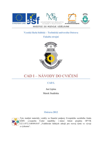
BABA FARID GROUP OF ENGINERING AND TECHNOLOGYTRIM – trtrim command is used to remove the extra or unwanted object from the autocad this command works only when the interferencebetween the two object is known in other words trim is trims off an object using cutting edges defined by other objects.Command- trim [enter] select the object first you need to keep then select the object you want to remove or TYPE “TR“ (TR DOUBLE ENTER and choose directly the object you want to remove)EXTEND:- EXExtend command is used to elongate the object this command gives you the facilities to extend an object to a boundary definedby the object.unextended objectextended object
(AUTO CAD 2014 FOR CIVIL, ELECTRONICS AND MECHANCIAL ENGINEERING) INTRODUCTION OF THE AUTO CAD SOFTWARE AND ITS UTILITIES IN THE ENGINEERING SOFTWARE. AutoCAD is a commercial software application for 2D and isometric and 3D computer-aided design (CAD) and Drafting software available since 1982 as a desktop application and