Transcription
British ColumbiaMinistry of Technology, Innovation and Citizens’ ServicesShared Services BCReal Property DivisionCAD Guidelines and StandardsApprovals:Todd EvansDrawings TechnologistLorraine McMillanDirector of Real Estate Policy andPerformance Management (SharedServices)Stephen MarguetExecutive Director of Real EstatePolicy and PerformanceManagement ( Shared Services)
CAD Guidelines and StandardsDocument ControlBritish ColumbiaMinistry of Technology, Innovation and Citizens’ ServicesShared Services BCReal Property Division1. Document ControlChange RecordDateAuthorVersionChange Reference07-20-200702-12-2009Todd EvansTodd Evans1.0CDocument CreatedDocument updated, IWS (SharedServices) file naming conventionremoved and added to IWS (SharedServices) Drawing policy. Title blockrestrictions ,Drawing file submissionschedule removed03-12-2013CristinaMartinez forTodd EvansD02-04-2014Todd EvansEDocument Update, addedDisclaimers and Limitation ofLiabilitiesDocument Update – Reorg DivisionName change RPDReviewersNamePositionCristina MartinezTodd EvansLorraine McMillanDrawings CoordinatorDrawings TechnologistDirector of Real Estate Policy andPerformance Management (SharedServices)Executive Director of Real EstatePolicy and PerformanceManagement ( Shared Services)Stephen MarguetShared Services RPD CAD Standards RevE.docxFeb 04, 2014 Original Release March 2008Page 2 of 49
CAD Guidelines and StandardsTable of ContentsBritish ColumbiaMinistry of Technology, Innovation and Citizens’ ServicesShared Services BCReal Property Division2. Table of Contents1.Document Control . 22.Table of Contents . 33.Quality Assurance of CAD Data . 73.1.Digital File Review . 73.2.Drawing File Format . 83.2.1.External references (XREF) . 83.2.2.Raster images . 83.2.3.Vertical products . 93.2.4.File submission . 94.Project Delivery . 104.1.Project Start-up . 104.1.1.CAD Master File Use . 104.1.2.Drawing Format. 104.2.Work in Progress . 104.3.Production of Contract Drawings . 104.4.Contract drawing submission . 114.5.Disclaimers and Limitation of Liabilities . 114.6.Copyright . 125.RPD Computer Aided Drafting Standards. 135.1.Layering Standards . 135.1.1.Colour Assignment Standard: Layer Colours and Pen Weights . 135.1.2.Graphic Data Sort into Related Data Groups . 135.1.3.Principal Data . 145.1.4.Supporting Data . 145.1.5.Provision for Creation of New Layers . 155.1.6.Layering Naming Convention . 155.2.Blocks Standards. 175.3.Text Style Standards . 185.4.Dimension Styles Standards . 185.4.1.Dimension Style Naming . 185.5.Linetype Standards. 195.6.Title Blocks and Graphic Scales . 205.6.1.Title Block Set-up . 205.6.2.Information in Title Blocks . 205.6.3.Drawing Scales . 205.7.Systems of Measurement and Preferred Scales . 215.7.1.Drawing scales examples . 215.8.Drawing legibility and Conventions . 215.9.Delivery Standard -Purge . 22Shared Services RPD CAD Standards RevE.docxFeb 04, 2014 Original Release March 2008Page 3 of 49
CAD Guidelines and StandardsTable of ContentsBritish ColumbiaMinistry of Technology, Innovation and Citizens’ ServicesShared Services BCReal Property DivisionAppendix A.Definitions . 23Appendix B.RPD Standard Layer Names . 24Appendix C.Layer Descrptions. 44Shared Services RPD CAD Standards RevE.docxFeb 04, 2014 Original Release March 2008Page 4 of 49
CAD Guidelines and StandardsTable of ContentsBritish ColumbiaMinistry of Technology, Innovation and Citizens’ ServicesShared Services BCReal Property DivisionThis Page Left Blank IntentionallyShared Services RPD CAD Standards RevE.docxFeb 04, 2014 Original Release March 2008Page 5 of 49
CAD Guidelines and StandardsTable of ContentsBritish ColumbiaMinistry of Technology, Innovation and Citizens’ ServicesShared Services BCReal Property DivisionCAD STANDARDSReal Property Division (RPD), Ministry of Technology, Innovation and Citizens’Services , Shared Service BC of the Province of British Columbia; ComputerAided Drafting (CAD) Standards are an integral component in the overall use andreuse of CAD files. Efficiencies occur to both RPD and future Consultant workwhen these standards are adhered to and are in the best interest and benefit ofall parties to comply with these standards.Efforts have been invested to make these standards as simplified as possible,giving liberties to the user and yet still provide RPD a critical means ofstandardisation which meets future archival values. These standards have beendeveloped and modeled after the Public Works and Government ServicesCanada (PWGSC) Cad Standards. If during project work certain standards forlayer naming convention etc. are required additional information and standardscan be obtained from the RPD Drawing Technologist.While striving to maintain the consistency necessary for life cycle maintainability,the RPD (Shared Services) CAD Standards are to be considered a dynamicdocument from which increased experience, technological advancement, andindustry wide standardization will provide future direction.Shared Services RPD CAD Standards RevE.docxFeb 04, 2014 Original Release March 2008Page 6 of 49
CAD Guidelines and StandardsQuality Assurance of CAD DataBritish ColumbiaMinistry of Technology, Innovation and Citizens’ ServicesShared Services BCReal Property Division3. Quality Assurance of CAD DataRPD (Shared Services) conducts a Quality Control Assessment of all deliveredCAD data files and printed drawing plans. This includes but is not limited to;drawing content, Title Block layout and font usage continuity throughout adrawing set and adherence to this CAD Standard Document.All hardcopy drawings or PDF submissions must match the submitted AutoCADfiles and be completed to the satisfaction of the RPD representative.Note that the content of the digital CAD data file is just as important as theprinted content and no drawing will be accepted as final until all issues areresolved. Delivered work that fails to meet any requirement in any of these areaswill result in the work being deemed unacceptable. The Consultant/DraftingService will be required to correct the problem(s) at their cost. Furthermore, RPDwill exercise its option to withhold payment of the contracted work as set out inthe contract terms until the work is made right. Alternatively, RPD may, if theConsultant/Drafting Service refuses to correct the problem, make the correctionsto the CAD data files and printed drawing plans and deduct the cost thereof fromthe Consultant/Drafting Service's fee. The Consultant/Drafting Service grants toRPD an irrevocable license to make such corrections and use the corrected CADdata files and printed drawing plans as it sees fit. Furthermore, RPD reserves theright to make use of the printed drawing plans resulting from the CAD data fileswith no obligation for payment until the CAD data files are corrected.3.1. Digital File ReviewThe following items will be reviewed to assure adherence to the CAD Standards.In all AutoCAD 2004 versions and later the AutoCAD Standards Checker will beused. On all other drawings done using previous versions of AutoCAD 2004 thefollowing will be checked manuallyCOLOUR ASSIGNMENTRPD Colour/Line Weight assignment must be used.LAYER STANDARDa) Only Standard Layer Names and/or RPD Layer names must be used.b) Entities must be on correct layers.TEXTSTYLE STANDARDOnly Standard AutoCAD SHX fonts or TTF fonts can be used.LINETYPE STANDARDa) Only Standard AutoCAD and/or RPD linetypes can be used.b) Linetype display variables must be used correctlyShared Services RPD CAD Standards RevE.docxFeb 04, 2014 Original Release March 2008Page 7 of 49
CAD Guidelines and StandardsQuality Assurance of CAD DataBritish ColumbiaMinistry of Technology, Innovation and Citizens’ ServicesShared Services BCReal Property DivisionDIMENSION STYLE STANDARDa) Associative Dimensions must be usedb) RPD naming convention must be usedEXTERNAL REFERENCINGThe use of external references will be authorized only if certain conditions aremet.RPD TITLE BLOCKS AND GRAPHIC SCALESa) RPD Title blocks must be used properly if providedb) Title blocks must contain the minimum information (section 3.6) if no RPDTitle block is providedc) Graphic Scales or written scale must accompany all Plans, Sections,Details and Elevations, etc.1:1 METRIC MODELDrawing must be modeled at full-size using metric units.REAL WORLD COORDINATE SYSTEMMaintain Coordinate systems integrity for 2D drawings.3.2. Drawing File FormatRPD requires all files to be generated with Microsoft Windows OperatingSystems. The CAD drawing format required for drawings is the AutoCAD nativeformat DWG file, Release 2000 to 2004. Drawing files submitted in Adobe PDF,Autodesk DWF or any other simplified formats is unacceptable. Any drawing filescreated in a foreign CAD program and converted to DWG must be fullycompatible with AutoCAD release 2004. Any problems arising from documentincompatibility will be the Consultant/Drafting Service responsibility.3.2.1. External references (XREF)The use of the external references (xrefs) will be conditionally authorized whenused in conjunction with the "Sheet Set Manager" to support the transmission ofdrawing files in a compressed format.In all the other cases, external references must be converted into blocks (Do notBIND XREFs, instead use BIND INSERT). In no circumstance shall a drawingcontain referenced symbols; they must be inserted as blocks.3.2.2. Raster imagesWhen separate raster images are included in a drawing, they must be positionedcorrectly. The raster images must be provided with the drawing along with anyspecific instructions needed to position them. (Coordinate, rotation, scaling)In the case of orthophotos attached to a drawing, a TFW file must be provided.Shared Services RPD CAD Standards RevE.docxFeb 04, 2014 Original Release March 2008Page 8 of 49
CAD Guidelines and StandardsQuality Assurance of CAD DataBritish ColumbiaMinistry of Technology, Innovation and Citizens’ ServicesShared Services BCReal Property Division3.2.3. Vertical productsWhere AutoCAD objects are used in vertical products such as AutodeskArchitectural Desktop, Autodesk Building Systems, Autodesk Map or AutodeskLand Desktop, appropriate 'object enablers' must be provided to view andmanipulate the objects.3.2.4. File submissionSubmission and transfer of drawing files will be through E-mail where possible. Ifusing Windows file compression (ZIP) to assist with file transfer the fileextension must be changed as provincial servers will strip out any zip files i.e.:Change Draw.Zip to Draw.Tif. Where file size exceeds the limit of E-mail, or ifthe above submission process is not available, compact disks (CD's) may bedelivered to the designated contact person.When using email for the drawings please provide the following information: Project LocationProject NameRPD Project NumberFile Name(s)RPD Building NumberShared Services RPD CAD Standards RevE.docxFeb 04, 2014 Original Release March 2008Page 9 of 49
CAD Guidelines and StandardsProject DeliveryBritish ColumbiaMinistry of Technology, Innovation and Citizens’ ServicesShared Services BCReal Property Division4. Project Delivery4.1. Project Start-upAll project drawings must be created using the standards contained herein.Where CAD services are provided externally, RPD CAD standards will also berequired of the consultant or CAD service. Pertinent CAD and as-built drawingsfor the related facility, as well as this document and associated Title Blocktemplate file will be provided if required.4.1.1. CAD Master File UseExisting digital information, when available, is used to form the foundation fornew project drawings. Any areas critical to the project should be verified by fieldchecking. New digital drawing files created must be modified to include the mostup-to-date information to the standards contained herein. Older CAD data, usedin new drawing files, must be updated to current CAD standards. The extent ofverification/updating of the existing digital files should be negotiated at the startup of project. All new work must meet this standard herein irrespective of thecondition of any existing files provided at the outset of work.4.1.2. Drawing FormatAll final drawings, including Title Blocks, shall be delivered in “Model space”.4.2. Work in ProgressIt is imperative that all work in progress shall be regularly backed up. RPDassumes no responsibility for losses resulting in failed data files. The consultant/ CAD service shall maintain the drawings in their own project directory until alldrawings for the project are completed, verified and accepted by RPD.4.3. Production of Contract DrawingsAll drawing sheet sizes will conform to the following:Sheet DesignationB1A0A2A3 (11 x 17 Tabloid)A4 (Letter / Portrait)Shared Services RPD CAD Standards RevE.docxFeb 04, 2014 Original Release March 2008Overall Size (mm)707 x 1000841 x 1189420 x 594297 x 420297 x 210Page 10 of 49
CAD Guidelines and StandardsProject DeliveryBritish ColumbiaMinistry of Technology, Innovation and Citizens’ ServicesShared Services BCReal Property Division4.4. Contract drawing submissionSubmission of final as-built contract drawings (record drawings) is to be in hardcopy as per contract and must be accompanied by digital AutoCAD as-built(record drawing) files. The hard copy drawings and digital files must representexactly, the as-built conditions on site at the time of completion of the project.ALL changes made to the project during the construction phase, by ALLdisciplines and sub-disciplines are to be incorporated into the contract drawingsat the record drawing stage prior to submittal.All changes must be clearly and properly denoted on the record drawing sheetsas per standard drafting convention on both the hard copy and electronic files.Procedures for denoting revisions should include, (but not be limited to) thefollowing:All revisions are to be recorded in the revision area of the title block, noted as perrevision number, date, reason for revision. Triangular symbols with numbersinside are to denote the changes on the drawings. Clouds are to be used todenote areas of revision where there is a significant area involved.The drawing must be saved such as to be printed without any page setup. Themain layout must be active and all the viewports adjusted and locked to thecorrect scale.4.5. Disclaimers and Limitation of LiabilitiesMaps, drawings, and data produced for RPD purposes should be considered forillustrative or reference purposes only by users outside of RPD.RPD and its agents, consultants, contractors, or employees provide thesematerials and information "as is" without warranty of any kind, implied or express,as to the information being accurate or complete, and without any warranty ofmerchantability and fitness for a particular purpose.RPD does not assume any legal liability or responsibility for the accuracy,completeness, or usefulness of the maps, drawings, data, or informationincidental thereto. RPD recommends that users exercise their own skill and carewith respect to their use or seek professional advice.Under no circumstances will RPD be liable to any person or business entity forany direct, indirect, special, incidental, consequential, or other damages as aresult of any use of the maps, drawings, data, or any information incidentalthereto, including, without limitation, any lost profits or business interruption.Shared Services RPD CAD Standards RevE.docxFeb 04, 2014 Original Release March 2008Page 11 of 49
CAD Guidelines and StandardsProject DeliveryBritish ColumbiaMinistry of Technology, Innovation and Citizens’ ServicesShared Services BCReal Property Division4.6. CopyrightThe Copyright Act protects all works (including drawings, charts, photos, etc.)from being copied without permission. All finally submitted CAD Data filesremain under ownership of the creating Consultant / CAD Service. RPDmaintains the right to use these files for the exclusive use of present and futureproject applications.Shared Services RPD CAD Standards RevE.docxFeb 04, 2014 Original Release March 2008Page 12 of 49
CAD Guidelines and StandardsRPD Computer Aided Drafting StandardsBritish ColumbiaMinistry of Technology, Innovation and Citizens’ ServicesShared Services BCReal Property Division5. RPD Computer Aided Drafting StandardsThe standards described in this section are general standards and, in the contextof a request for proposal, specific instructions can be added or can modify these.5.1. Layering StandardsLayering structure is of high importance to RPD. The explanations below outlinesthe creation and rational for the use of layers and must be adhered to unlessapproved by RPD representative. Independent contractors can add layers whichare not included in the template but the layers must adhere to RPD namingconventions5.1.1. Colour Assignment Standard: Layer Colours and Pen WeightsColour is to be used as a method of defining line weight to the plotter. Layersmust be assigned appropriate colours and entities should be created with colour"bylayer" where possible, except as provided for in the creation of symbols.LineSuggested Line Weight Settings:Centre LinesAxis Grid LinesDimension LinesPhantom LinesIntermediate Contour LinesHatchingText -Normal Leader and Extension LinesHidden LinesText -Sub HeadingsIndex Contour LineVisible Object OutlinesCuttingMatch LinesSection Lines Viewing Planes Reference Lines Text –TitlesMajor HeadingsTitle Sheet BorderWeightExtra Thin0.100mmThin0.15 to0.250mmMedium0.300mm to0.500mmThick0.700mm1.000mmIf colour dependent plot output, then the Plotter.CTB must be attached with thefinal submission to ensure proper colour designation.5.1.2. Graphic Data Sort into Related Data GroupsLayers are used to sort the data types being depicted by the line work (Not tosort line weights, line types, colours or other schemes). This is the only way toidentify what entities on a graphic screen are supposed to represent withoutresorting to annotations. (I.e. does a rectangle represent a building outline, aShared Services RPD CAD Standards RevE.docxFeb 04, 2014 Original Release March 2008Page 13 of 49
CAD Guidelines and StandardsRPD Computer Aided Drafting StandardsBritish ColumbiaMinistry of Technology, Innovation and Citizens’ ServicesShared Services BCReal Property Divisionconcrete pad, a storage tank or is it an annotation box?). The Layering standardsare to be used to create the layers to accommodate these groupings of relateddata.To simplify the Layering, drawing data can be broken into two major groupings,Principal Data and Supporting Data. The level of complexity and number oflayers required for the two groups is significantly different.5.1.3. Principal DataPrincipal Data is contained mainly on the plan views of the facility, i.e., BasePlan, Floor Plan, Site Plan, etc. This type of data requires strict adherence tolayer naming and proper grouping of data. The line work that is used to depictfacility components must always be drawn using the most up-to-date accurateinformation available. Line work depicting objects must be placed on the properstandard layer according to the data type being represented by the line work. Forexample, on a Floor Plan, the walls, doors, windows, and bathroom fixtures musthave separate layers. Note that where plans are specifically titled "New" (or"Existing) the N (or E) Construction Status Extension layer modifier may beomitted, but all disparate Construction Status Extensions must be included.Existing Floor Plan NT-NA-WD-EXTH-PF-FIXArchitectural Wall Interior NewArchitectural Wall Interior RemoveArchitectural Wall Outline ExteriorArchitectural Door InteriorArchitectural Door Interior NewArchitectural Window ExteriorMechanical Plumbing FixturesInterior Walls NewInterior Walls To Be RemovedBuilding Outline (Existing Implied)Interior Doors (Existing Implied)Interior Doors NewExterior Windows (Existing Implied)Toilets, Bathtubs, etc. (Existing Implied)Note: When a symbol is placed to represent an object, it must beplaced on a symbol layer, as in the following examples.Symbols Example:G-TL-SYM - General Title block Symbols - Symbols, key plan, north arrow, barscale5.1.4. Supporting DataSupporting Data is made up of Sections, Details, Elevations, Schedules andLegends, Title Blocks, etc. This type of data requires minimal layeringbreakdown. Line work in a detail representing different components does notneed to be placed on separate layers. For example, a building construction detailcan be drawn with a foundation wall; frame wall, floors, and roof line work on asingle layer, although the dimensions, annotation and hatching should beseparated as indicated in the example below. Colour should be set "bylayer" forthe majority of entities on a layer and specifically where necessary to obtainvarying line weights in that layer.Shared Services RPD CAD Standards RevE.docxFeb 04, 2014 Original Release March 2008Page 14 of 49
CAD Guidelines and StandardsRPD Computer Aided Drafting StandardsBritish ColumbiaMinistry of Technology, Innovation and Citizens’ ServicesShared Services BCReal Property DivisionDetail ral Detail LineworkArchitectural Detail TextArchitectural Detail DimensionsArchitectural Detail HatchingWall, Floor and Roof LineworkAnnotations, Title, Graphic Scale, etc.DimensionsHatching - Insulation, Wood Grain, etc.Schedule Example:A-SC-LINA-SC-TXTArchitectural Schedule LineworkArchitectural Schedule TextSchedule Grid or LineworkSchedule Data, AnnotationSupporting Data can also appear on plan views:H-PL-TXTMechanical Plan TextS-PL-DIMStructural Plan DimensionsTitles, Graphic Scale, AnnotationBubblesDimensions5.1.5. Provision for Creation of New LayersAs all possibilities are not covered in the existing layer list, it is possible (andnecessary) to create new layer names for some objects. The rules for creation ofnew layers are:a)b)c)d)e)Proper Standard Layer for object must not already existMust follow standard formatMust use existing Discipline Group (i.e.: G General)Must use existing Group field (i.e. : G-TL General Title Block)Must use existing 3 character grouping from Single Layer Field or FirstLayer Name Extension - G-TL-DET i.e.: General Title Block Details5.1.6. Layering Naming ConventionLayering of CADD information must adhere to the following Layering NamingConvention. The layer is the basic tool for organizing and managing graphicinformation. Layers are used to sort graphic objects into groupings of relateddata. Alphanumeric layer nomenclature format is designed to sort this data in aspecific manner.The layer name structure consists of 5 fields separated by hyphens. The first 3fields, consisting of the discipline, group and single layer fields, are mandatorywhile the last 2 are optional fields allowing a more precise identification wherenecessary.Shared Services RPD CAD Standards RevE.docxFeb 04, 2014 Original Release March 2008Page 15 of 49
CAD Guidelines and StandardsRPD Computer Aided Drafting StandardsBritish ColumbiaMinistry of Technology, Innovation and Citizens’ ServicesShared Services BCReal Property DivisionNote: See Appendix B for Field DescriptionsThe Discipline Field identifies the discipline responsible for the layer content.Where an object cannot be associated with a specific discipline, or is applicableto all disciplines, the special General Information Field "G" may be used.The defined discipline fields are:ABCEGHILMRSArchitectureBridge EngineeringCivil Engineering, Site work andLandscapingElectrical SystemsGeneral InformationMechanicalInterior DesignLegal SurveysMarineReal Property Space ManagementStructureThe Group Field identifies groupings of common types of drawing informationrelevant to each discipline. The Group Fields defined for each Discipline Field arelisted in the Standard Layer List. In addition to the Group Fields defined in theStandard Layer List there are some common Group Fields to place supportinggraphic data such as sections and details, etc.The Single Layer Field subdivides the classifications created by the Disciplineand Group Fields to identify each layer more precisely. The Single Layer Fieldsdefined for Group Fields under each Discipline Field are listed in the StandardLayer List and described in the Layer Field DescriptionThe First Layer Name Extension allows information pertaining to PhysicalProperties, Materials, Graphics and Text to be included. The extensions may beused with any valid layer from the Standard Layer List. They may also be usedas a Single Layer Field value where appropriate.The Second Layer Name Extension allows information pertaining to Geometry,Construction, Status, Second Language and Numerical Options to be included.The extensions may be used with any valid layer from the Standard Layer List.Shared Services RPD CAD Standards RevE.docxFeb 04, 2014 Original Release March 2008Page 16 of 49
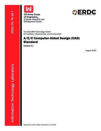
CAD Guidelines and StandardsRPD Computer Aided Drafting StandardsBritish ColumbiaMinistry of Technology, Innovation and Citizens’ ServicesShared Services BCReal Property DivisionValid Layer Name FormatsOnly 4 variants of the layer name format will be accepted, as indicated below:Note: Add an underscore character at the end of a valid layername to append free text to the layer name e.g.5.2. Blocks StandardsAutoCAD blocks are used to group entities. These graphic blocks shall not beexploded. Nested blocks are allowed only to group a preset of simple blocks.Symbols shall be created with linetype and colour Byblock. This allows completecontrol over the appearance of the symbol. By default the symbol will take on theproperties of the layer it is placed on but it can be changed to suit requirementsindependent of the layer settings.There is two different ways for creation and insertion of AutoCAD blocks withbasic rules for creating each:a) Simple blocks with one data type, e.g., toilet fixtures, furnitureo Created on layer 0o b) Must be inserted on proper layerb) Complex graphics requiring use of multiple data typeso Each data type is created on its proper layero Colour and linetype must be Bylayer or Byblock so that colour andlinetypeMay be assigned to the symbol regardless of the layer properties the symbol isinserted on, e.g. title blocks created with objects on different layersCut and Paste blocks are not acceptable. If this function is used in the creation ofthe drawing set, all of these block types must be exploded and the file purged ofits entities before final delivery is accepted.Shared Services RPD CAD Standards RevE.docxFeb 04, 2014 Original Release March 2008Page 17 of 49
CAD Guidelines and StandardsRPD Computer Aided Drafting StandardsBritish ColumbiaMinistry of Technology, Innovation and Citizens’ ServicesShared Services BCReal Property Division5.3. Text Style StandardsText styles for use in drawings must be created using Standard AutoCAD SHX orTTF font files. Text style usage should be uniform throughout each projectdrawing setHeight of these text styles must be set to 0 (Not fixed) or the dimension textheight variable, DIMTXT, will be overridden and the text height for dimensions,as well as normal text, will not change to suit differen
standardisation which meets future archival values. These standards have been developed and modeled after the Public Works and Government Services Canada (PWGSC) Cad Standards. If during project work certain standards for layer naming convention etc. are required additional information and standards can be obtained from the RPD Drawing .