Transcription
Lecture Notes onCAD-CAMIV B. Tech I semester (JNTUH-R15)Prepared byDr. D GOVARDHAN, Professor, AESuresh Kumar R, Assistant Professor, AEDEPARTMENT OF AERONAUTICAL ENGINEERINGINSTITUTE OF AERONAUTICAL ENGINEERING(Autonomous)Dundigal, Hyderabad, Telangana 500043
SYLLABUSUNIT-IFundamentals of cad cam automation, design process, application of computers for design, benefits of cadcomputer application for cad application - computer peripherals, design work station, graphic terminal CADsoftware, definition of system software and application software, CAD database and structureGeometric modeling: 3-D wire frame modeling, wire frame entities and their definitions, interpolation andapproximation of curves, concepts of parametric and nonparametric representation, curve fitting techniques,definition of cubic spline, Bezier and b-spline.UNIT-IISurface modeling : Algebraic & Geometric form , Parametric Space Surface, Blending functions ,Parameterization of surface patch , sub dividing , cylindrical surface , ruled surface , surface of revolution ofspherical surface , composite surface , Bezier surfaces , Regenerative surface & pathological conditions.Solid modeling: Definition of cell composition & spatial occupancy enumeration, sweep representation,constructive & solid geometry, boundary representations.UNIT-IIINC Control production systems: Numerical control , elements of NC system , NC part programming ;Methods of NC part programming , Manual part programming , computer assisted part programming, postprocessor , computerized part program , SPPL (A Simple programming language) , CNC , DNC , & Adoptivecontrol systems.UNIT-IVGroup Technology: Part families, parts classification & coding, production flow analysis, machine celldesign.Computer aided process planning, difficulties in traditional process planning, computer aided processplanning: retrieval & generative type, machinability data systems.Computer aided manufacturing resource planning: Material resource planning input to MRP, MRP outputrecords, benefits of MRP, Enterprise resource planning, capacity requirements planning. UNIT-VUNIT-VFlexible manufacturing system: FMS Equipment, FMS layouts, Analysis methods of FMS, Benefits of FMS.Computer aided quality control: Automated inspection offline online. Contact & noncontact co-ordinatemeasuring machines, machine vision.Computer integrated manufacturing: CIM systems, benefits of CIM.TEXT BOOKS:1. CAD/CAM/GROOVER.P/PEARSON education.2. CAD/CAM Concepts & applications/Alavala/PHIREFERENCE BOOKS:1. CAD/CAM Principles and Applications / P.N.RAO/TMH.2. CAD/CAM Theory and Practice / Ibrahim Zeid / TMH.3. CAD/CAM/CIM Radha Krishnan & Subramanian / New age.4. Principles of computer Aided Design and Manufacturing / Fanlc / Amirouche / Pearson.5. Computer Numerical Control Concepts and Programming / Warrens & Seames / Thomson.
UNIT 1INTRODUCTIONCAD/CAMCAD/CAMis a term which means computer-aideddesign and computer- aidedmanufacturing. It is the technology concerned with the use of digital computers to perform certainfunctions in design and production. This technology is moving in the direction of greaterintegration of design and manufacturing, two activities which have traditionally been treated asdistinct and separate functions in a production firm. Ultimately, CAD/CAM will provide thetechnology base for the computer-integrated factory of the future.Computer-aided design (CAD) can be defined as the use of computer systems toassist in the creation, modification, analysis, or optimization of a design. Thecomputersystems consist of the hardware and software to perform the specialized design functionsrequired by the particular user firm. The CAD hardware typically includes the computer, one ormore graphics display terminals, keyboards, and other peripheral equipment.The CADsoftware consists of the computer programs to implement computer graphics on the systemplus application programs to facilitate the engineering functions of the user company. Examplesof these application programs include stress-strain analysis of components, dynamic response ofmechanisms, heat-transfer calculations, and numerical control part programming. The collectionof application programs will vary from one user firm to the next because their product lines,manufacturing processes, and customer markets are different. These factors give rise to differencesin CAD system requirements.Computer-aided manufacturing (CAM) can be defined as the use of computersystems to plan, manage, and control the operations of a manufacturing plant through eitherdirect or indirect computer interface with the plant's production resources. As indicated by thedefinition, the applications of computer-aided manufacturing fall into two broad categories:1. Computer monitoring and control. These are the direct applications in which thecomputer is connected directly to the manufacturing process for the purpose ofmonitoring or controlling the process.3
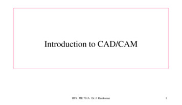
2. Manufacturing support applications. These are the indirect applications in which thecomputer is used in support of the production operations in the plant, but there is nodirect interface between the computer and the manufacturing process.The distinction between the two categories is fundamental to an understandingof computer-aided manufacturing. It seems appropriate to elaborate on our brief definitions of thetwo types.Computer monitoring and control can be separated into monitoring applicationsand control applications. Computer process monitoring involves a direct computer interface withthe manufacturing process for the purpose of observing the process and associated equipmentand collecting data from the process. The computer is not used to control the operationdirectly. The control of the process remains in the hands of human operators, who may beguided by the information compiled by the computer.Computer process control goes one step further than monitoring by not only observingthe process but also controlling it based on the observations. The distinction betweenmonitoring and control is displayed in Figure. With computer monitoring the flow of databetween the process and the computer is in one direction only, from the process to the computer.In control, the computer interface allows for a two-way flow of data. Signals are transmittedfrom the process to the computer, just as in the case of computer monitoring. In addition, thecomputer issues command signals directly to the manufacturing process based on controlalgorithms contained in its software.In addition to the applications involving a direct computer-process interface for the purpose ofprocess monitoring and control, computer-aided manufacturing also includes indirectapplications in which the computer serves a support role in the manufacturing operations ofthe plant. In these applications, the computer is not linked directly to the manufacturingprocess.4
Computer monitoring versus computer control:(a) computer monitoring, (b) computer control.Instead, the computer is used "off-line" to provide plans, schedules, forecasts,instructions, and information by which the firm's production resources can be managed moreeffectively. The form of the relationship between the computer and the process is representedsymbolically in Figure. Dashed lines are used to indicate that the communication and controllink is an off-line connection, with human beings often required to consumate theinterface. Some examples of CAM for manufacturing support that are discussed insubsequent chapters of this book include:Numerical control part programming by computers. Control programs are prepared forautomated machine tools.Computer-automated process planning. The computer prepares a listing of the operationsequence required to process a particular product or component.Computer-generate work standards. The computer determines the time standard for aparticular production operation.Production scheduling. The computer determines an appropriate schedule for meetingproduction requirements.Material requirements planning. The computer is used to determine when to order rawmaterials and purchased components and how many should be ordered to achieve the productionschedule.Shop floor control. In this CAM application, data are collected from the factory todetermine progress of the various production shop orders.In all of these examples, human beings are presently required in the application either toprovide input to the computer programs or to interpret the computer output and implement therequired action.CAM for manufacturing support.5
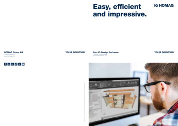
THE PRODUCT CYCLE AND CAD/CAMFor the reader to appreciate the scope of CAD/CAM in the operations of a manufacturingfirm, it is appropriate to examine the various activities and functions that must be accomplishedin the design and manufacture of a product. We will refer to these activities and functions as theproduct cycle.A diagram showing the various steps in the product cycle is presented in Figure. Thecycle is driven by customers and markets which demand the product. It is realistic to think ofthese as a large collection of diverse industrial and consumer markets rather than one monolithicmarket. Depending on the particular customer group, there will be differences in the way theproduct cycle is activated. In some cases, the design functions are performed by the customer andthe product is manufactured by a different firm. In other cases, design and manufacturing isaccomplished by the same firm. Whatever the case, the product cycle begins with a concept, anidea for a product. This concept is cultivated, refined, analyzed, improved, and translated intoa plan for the product through the design engineering process. The plan is documented by draftingIi set of engineering drawings showing how the product is made and providing a set ofspecifications indicating how the product should perform.Except for engineering changes which typically follow the product throughout its lifecycle, this completes the design activities in Figure. The next activities involve themanufacture of the product. A process plan is formulated whichspecifies the sequence of production operations required to make the product. New equipment andtools must sometimes be acquired to produce the new product. Scheduling provides a planthat commits the company to the manufacture of certain quantities of the product by certain dates.Once all of these plans are formulated, the product goes into production, followed by qualitytesting, and delivery to the customer.6
PRODUCT CYCLE IN CONVENTIONAL ENVIRONMENT7
PRODUCT CYCLE IN AN COMPUTERISEDENVIRONMENTProduct cycle (design and manufacturing).The impact of CAD/CAM is manifest in all of the different activities in the product cycle, asindicated in Figure. Computer-aided design and automated drafting are utilized in theconceptualization, design, and documentation of the product. Computers are used in processplanning and scheduling to perform these functions more efficiently. Computers are used inproduction to monitor and control the ycontrol,perform inspections and performance tests on the product and itscomponents.As illustrated in Figure, CAD/CAM is overlaid on virtually all of the activities andfunctions of the product cycle. In the design and production operations of a modemmanufacturing firm, the computer has become a pervasive, useful, and indispensable tool. It is8
strategically important and competitively imperative that manufacturingfirmsandpeople who are employed by them understand CAD/CAM.theAUTOMATION AND CAD/CAMAutomation is defined as the technology concerned with the application ofcomplex mechanical, electronic, and computer-based systems in the operation andcontrol of production. It is the purpose of this section to establish the relationshipbetween CAD/CAM and automation.As indicated in previous Section, there are differences in the way theproduct cycle is implemented for different firms involved in production. Productionactivity can be divided into four main categories:l. Continuous-flow processes2. Mass production of discrete products3. Batch production4. Job shop productionThe definitions of the four types are given in Table. Therelationships among thefour types in terms of product variety and production quantities can be conceptualizedas shown in Figure. There is some overlapping of the categories as the figureindicates. Table provides a list of some of the notable achievements in automationtechnology for each of the four production types.One fact that stands out from Table is the importance of computertechnology in automation. Most of the automated production systems implementedtoday make use of computers. This connection between the digital computer andmanufacturing automation may seem perfectly logical to the reader. However, thislogical connection has not always existed. For one thing, automation technology9
TABLE Four Types of ProductionCategoryDescriptionl. Continuous-flow processes2. MassproductsproductionofContinuous dedicated production of largeamounts of bulk product. Examples includecontinuous chemical plants andoilrefineriesdiscrete Dedicated production of large quantities ofone product (with perhaps limited modelvariations). Examples include automobiles,appliances, and engine blocks.3. Batch productionProduction of medium lot sizes of the sameproduct or component. The lots may beproduced once or repeated periodically.Examples include books, clothing, andcertain industrial machinery.4. Job shop productionProduction of low quantities, often one of akind, of specialized products. The productsare often customized and technologicallycomplex. Examples include .Four production types related to quantity and product variation10
TABLE Automation Achievements for the Four Types of ProductionCategoryl. Continuous-flowprocessesAutomation achievementsFlow process from beginning to endSensor technology available to measure important processvariablesUse of sophisticated control and optimization strategiesFully computer-automated plants2. Mass productionof discrete productsAutomated transfer machinesDial indexing machinesPartially and fully automated assembly linesIndustrial robots for spot welding, parts handling, machineloading, spray painting, etc.Automated materials handling systemsComputer production monitoring3. Batch productionNumerical control (NC), direct numerical control (DNC),computer numerical control (CNC)Adaptive control machiningRobots for arc welding, parts handling, etc.Computer-integrated manufacturing systems4. Job shop productionNumerical control, computer numerical controlFUNDAMENTALS OF CADINTRODUCTIONThe computer has grown to become essential in the operations of business,government, the military, engineering, and research. It has also demonstrated itself,especially in recent years, to be a very powerful tool in design and manufacturing. Inthis and the following two chapters, we consider the application of computertechnology to the design of a product. This secton provides an overview ofcomputer-aided design.The CAD system definedAs defined in previous section, computer-aided design involves any type ofdesign activity which makes use of the computer to develop, analyze, or modify an11
engineering design. Modem CAD systems (also often called CAD/CAM systems) arebased on interactive computer graphics (ICG).Interactive computer graphics denotes auser-oriented system in which the computer is employed to create, transform, anddisplay data in the form of pictures or symbols. The user in the computer graphicsdesign system is the designer, who communicates data and commands to thecomputer through any of several input devices. The computer communicates with theuser via a cathode ray tube (CRT). The designer creates an image on the CRT screenby entering commands to call the desired software sub-routines stored in thecomputer. In most systems, the image is constructed out of basic geometric elementspoints, lines, circles, and so on. It can be modified according to the commands of thedesigner- enlarged, reduced in size, moved to another location on the screen, rotated,and other transformations. Through these various manipulations, the required detailsof the image are formulated.The typical ICG system is a combination of hardware and software. Thehardware includes a central processing unit, one or more workstations (including thegraphics display terminals), and peripheral devices such as printers. Plotters, anddrafting equipment. Some of this hardware is shown in Figure. The software consistsof the computer programs needed to implement graphics processing on the system.The software would also typically include additional specialized applicationprograms to accomplish the particular engineering functions required by the usercompany.It is important to note the fact that the ICG system is one component of acomputer-aided design system. As illustrated in Figure, the other major component isthe human designer. Interactive computer graphics is a tool used by the designer tosolve a design problem. In effect, the ICG system magnifies the powers of thedesigner. This bas been referred to as the synergistic effect. The designer performsthe portion of the design process that is most suitable to human intellectual skills(conceptualization, independent thinking); the computer performs the task: bestsuited to its capabilities (speed of calculations, visual display, storage of large8IWWIts of data), and the resulting system exceeds the sum of its components.There are several fundamental reasons for implementing a computer-aideddesign system.12
l. To increase the productivity of the designer. This is accomplished byhelping the designer to the product and its component subassemblies and parts; andby reducing the time required in synthesizing, analyzing, and documenting thedesign. This productivity improvement translates not only into lower design cost butalso into shorter project completion times.2. To improve the quality of design. A CAD system permits a morethorough engineering analysis and a larger number of design alternatives can beinvestigated. Design errors are also reduced through the greater accuracy provided bythe system. These factors lead to a better design.3. To improve communications. Use of a CAD system provides betterengineering drawings, more standardization in the drawings, better documentation ofthe design, fewer drawing errors and greater legibility.4. To create a database for manufacturing. In the process of creating thedocumentation for the product design (geometries and dimensions of the product andits components, material specifications for components, bill of materials, etc.), muchof the required database to manufacture the product is also created.THE DESIGN PROCESSBefore examining the several facets of computer-aided design, let us firstconsider the general design process. The process of designing something ischaracterized by Shigley as an iterative procedure, which consists of six identifiablesteps or phases:l. Recognition of need2. Definition of problem3. Synthesis4. Analysis and optimization5. Evaluation6. PresentationRecognition of need involves the realization by someone that a problemexists for which some corrective action should be taken. This might be theidentification of some defect in a current machine design by an engineer or theperception of a new product marketing opportunity by a salesperson. Definition of13
the problem involves a thorough specification of the item to be designed. Thisspecification includes physical and functional characteristics, cost, quality, andoperating performance.Synthesis and analysis are closely related and highly interactive in thedesign process. A certain component or subsystem of the overall system isconceptualized by the designer, subjected to analysis, improved through this analysisprocedure, and redesigned. The process is repeated until the design has beenoptimized within the constraints imposed on the designer. The components andsubsystems are synthesized into the final overall system in a similar interactivemanner.Evaluation is concerned with measuring the design against the specificationsestablished in the problem definition phase. This evaluation often requires thefabrication and testing of a prototype model to assess operating performance, quality,reliability, and other criteria. The final phase in the design process is the presentationof the design. This includes documentation of the design by means of drawings,material specifications, assembly lists, and so on. Essentially, the documentationrequires that a design database be created. Figure illustrates the basic steps in thedesign process, indicating its iterative nature.The general design process as defined by Shigley .14
Engineering design has traditionally been accomplished on drawing boards, with thedesign being documented in the form of a detailed engineering drawing. Mechanicaldesign includes the drawing of the complete product as well as its components andsubassemblies, and the tools and fixtures required to manufacture the product.Electrical design is concerned with the preparation of circuit diagrams, specificationof electronic components, and so on. Similar manual documentation is required inother engineering design fields (structural design, aircraft design, chemicalengineering design, etc.). In each engineering discipline, the approach hastraditionally been to synthesize a preliminary design manually and then to subjectthat design to some form of analysis. The analysis may involve sophisticatedengineering calculations or it may involve a very subjective judgment of the aestheteappeal possessed by the design. The analysis procedure identifies certainimprovements that can he made in the design. As stated previously, the process isiterative. Each iteration yields an improvement in the design. The trouble with thisiterative process is that it is time consuming. Many engineering labor hours arerequired to complete the design project.THE APPLICATION OF COMPUTERS FOR DESIGNThe various design-related tasks which are performed by a modemcomputer-aided design-system can be grouped into four functional areas:l. Geometric modeling2. Engineering analysis3. Design review and evaluation4. Automated draftingThese four areas correspond to the final four phases in Shigley's generaldesign process, illustrated in Figure. Geometric modeling corresponds to thesynthesis phase in which the physical design project takes form on the ICG system.Engineering analysis corresponds to phase 4, dealing with analysis and optimization.Design review and evaluation is the fifth step in the general design procedure.Automated drafting involves a procedure for converting the design image dataresiding in computer memory into a hard-copy document. It represents an important15
method for presentation (phase 6) of the design. The following four sections exploreeach of these four CAD functions.Geometric modelingIn computer-aided design, geometric modeling is concerned with thecomputer-compatible mathematical description of the geometry of an object. Themathematical description allows the image of the object to be displayed andmanipulated on a graphics terminal through signals from the CPU of the CADsystem. The software that provides geometric modeling capabilities must be designedfor efficient use both by the computer and the human designer.To use geometric modeling, the designer constructs, the graphical image ofthe object on the CRT screen of the ICG system by inputting three types16of
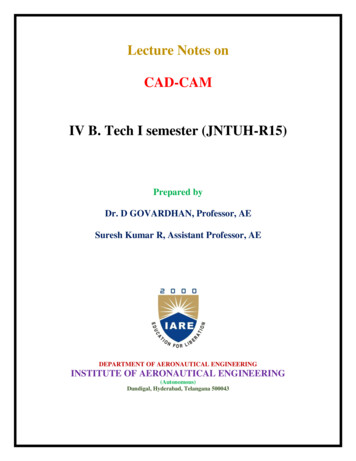
commands to the computer. The first type of command generates basic geometricelements such as points, lines, and circles. The second command type is used toaccomplish scaling, rotating, or other transformations of these elements. The thirdtype of command causes the various elements to be joined into the desired shape ofthe object being creaed on the ICG system. During the geometric modeling process,the computer converts the commands into a mathematical model, stores it in thecomputer data files, and displays it as an image on the CRT screen. The model cansubsequently be called from the data files for review, analysis, or alteration.There are several different methods of representing the object in geometricmodeling. The basic form uses wire frames to represent the object. In this form, theobject is displayed by interconnecting lines as shown in Figure. Wire framegeometric modeling is classified into three types depending on the capabilities of theICG system. The three types are:l. 2D. Two-dimensional representation is used for a flat object.2. 2½D. This goes somewhat beyond the 2D capability by permitting athree-dimensional object to be represented as long as it has no side-wall details.3. 3D. This allows for full three-dimensional modeling of a more complexgeometry.Example of wire-frame drawing of a part.17
Even three-dimensional wire-frame representations of an object are sometimesinadequate for complicated shapes. Wire-frame models can be enhanced by severaldifferent methods. Figure shows the same object shown in the previous figure butwith two possible improvements. lbe first uses dashed lines to portray the rear edgesof the object, those which would be invisible from the front. lbesecondenhancement removes the hidden lines completely, thus providing a less clutteredpicture of the object for the viewer. Some CAD systems have an automatic "hiddenline removal feature," while other systems require the user to identify the lines thatare to be removed from view. Another enhancement of the wire-frame modelinvolves providing a surface representation which makes the object appear solid tothe viewer. However, the object is still stored in the computer as a wire-frame model.Same workpart as shown in Figure 4.4 but with (a) dashed lines lO show rear edgesof part, and (b) hidden-line removal. (Courtesy of Computervision Corp.)18
Solid model of yoke part as displayed on a computer graphics system. (Courtesy ofComputervision Corp.)The most advanced method of geometric modeling is solid modeling inthree dimensions. This method, illustrated in Figure, typically uses solid geometryshapes called primitives to construct the object.Another feature of some CAD systems is color graphics capability. Bymeans of colour, it is possible to display more information on the graphics screen.Colored images help to clarify components in an assembly, or highlight dimensions,or a host of other purposes.Engineering analysisIn the formulation of nearly any engineering design project, some type ofanalysis is required. The analysis may involve stress-strain calculations, heat-transfercomputations, or the use of differential equations to describe the dynamic behavior ofthe system being designed. The computer can be used to aid in this analysis work. Itis often necessary that specific programs be developed internally by the engineeringanalysis group to solve a particular design problem. In other situations, commerciallyavailable general-purpose programs can be used to perform the engineering analysis.Turnkey CAD/CAM systems often include or can be interfaced toengineering analysis software which can be called to operate on the current designmodel.19
We discuss two important examples of this type:Analysis of mass propertiesFinite-element analysisThe analysis of mass properties is the analysis feature of a CAD system thathas probably the widest application. It provides properties of a solid object beinganalyzed, such as the surface area, weight, volume, center of gravity, and moment ofinertia. For a plane surface (or a cross section of a solid object) the correspondingcomputations include the perimeter, area, and inertia properties.Probably the most powerful analysis feature of a CAD system is the finiteelement method. With this technique, the object is divided into a large number offinite elements(usually rectangularor triangularshapes)which form aninterconnecting network of concentrated nodes. By using a computer with significantcomputational capabilities, the entire Object can be analyzed for stress-strain, heattransfer, and other characteristics by calculating the behavior of each node. Bydetermining the interrelating behaviors of all the nodes in the system, the behavior ofthe entire object can be assessed.Some CAD systems have the capability to define automatically the nodesand the network structure for the given object. lbe user simply defines certainparameters for the finite-element model, and the CAD system proceeds with thecomputations.The output of the finite-element analysis is often best presented by thesystem in graphical format on the CRT screen for easy visualization by the user, Forexample, in stress-strain analysis of an object, the output may be shown in the formof a deflected shape superimposed over the unstressed object. This is illustrated inFigure. Color graphics can also be used to accentuate the comparison before andafter deflection of the object. This is illustrated in Figure for the same image as thatshown in Figure . If the finite-element analysis indicates behavior of thedesignwhich is undesirable, the designer can modify the shape and recompute the finiteelement analysis for the revised design.20
Finite-element modeling for stress-strain analysis. Graphics display shows strainedpart superimposed on unstrained part for comparison.Design review and evaluationChecking the accuracy of the design can be accomplished conveniently onthe graphics terminal. Semiautomatic dimensioning and tolerancing routines whichassign size specifications to surfaces indicated by the user help to reduce thepossibility of dimensioning errors. The designer can zoom in on part design detailsand magnify the image on the graphics screen for close scrutiny.A pr
Fundamentals of cad cam automation, design process, application of computers for design, benefits of cad computer application for cad application - computer peripherals, design work station, graphic terminal CAD software, definition of system software and application software, CAD database and structure