Transcription
Security System 3808AInstallation GuideThis product is intended for installation by a professionalinstaller only! Attempts to install this product by a person other than a trained professional may result in severedamage to a vehicle’s electrical system and components. 2012 Directed Electronics, Vista, CAN3808A 2012-01
Bitwriter , Code Hopping , Doubleguard , ESP , FailSafe , Ghost Switch , Learn Routine , Nite-Lite , Nuisance Prevention Circuitry, Revenger , Silent Mode ,Soft Chirp , Stinger , Valet , Vehicle Recovery System ,VRS , and Warn Away are all Trademarks or RegisteredTrademarks of Directed Electronics.The Bitwriter (p/n 998U)requires chip version 2.8 ornewer to program this unit.Bitwriters with a date code of 6a or older require an IC upgrade (p/n998M). Some bitwriters with a date code of 6B do not require the ICupgrade, refer to tech tip # 1112 for more information.
ContentsWiring Diagram. 510 Pin Main Harness. 54 pin Auxiliary/Pin switch Monitor Harness. 83 pin Door Lock Harness. 95 pin RKE (Remote Keyless Entry) Harness. 9Light flash Polarity Setting. 10Programming System Features. 11Feature Menu. 11Feature Descriptions (consumer factory default settings are in bold). 12Remote Control Programming and Deletion. 14System Testing and Impact Sensor Adjusting. 15RF Security Setting. 15OEM Security Setting. 16Dealer Security. 16Nuisance Prevention Circuitry (NPC). 17Long Term Event History. 17Table of Zones. 17Rapid Resume Logic. 17Troubleshooting: Alarm. 18
4 2012 Directed. All rights reserved.
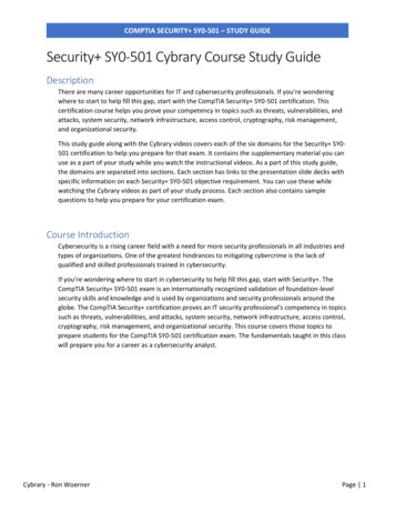
Wiring DiagramSensorAdjustmentAntenna(Red Plug)Programmer PortLight FlashPolarity Jumper DetailLIGHT FLASH POLARITY(10A (MAXIMUM) FUSE JUMPER)(Blue Plug)Valet/LED Port10 Pin Main HarnessBLACK(-) CHASSIS GROUNDRED( ) 12V CONSTANT POWERWHITE/BLACKLIGHT FLASH RELAY ISOLATION WIRE (87a)WHITE( /-) LIGHT FLASH RELAY OUTPUT (30)YELLOW( ) IGNITION INPUTRED/WHITE(-) 200 mA TRUNK POP OUTPUTBROWN(-) 200 mA HORN/SIREN OUTPUTORANGE(-) 500 mA GROUND WHEN ARMED OUTPUTVIOLET( ) DOOR TRIGGER INPUTGREEN(-) DOOR TRIGGER INPUT 2012 Directed. All rights reserved.5
This system can be configured in two different ways.1. as an add-on security system to the vehicles factory keyless entry system.2. as a full security system added to the vehicle.This guide covers the installations of both configurations and is labeled respectively.BLACK (-) CHASSIS GROUNDThis wire is the main unit’s source of ground. DO NOT connect this wire to any factory ground points; theycan cause noise and/or current loss which can affect system performance. Ground the main unit and anyaccessories to the same point in the vehicle, (preferably the kick panel). Scrape away any paint and use afactory bolt or make your own ground with a self-tapping screw and a star washer[Required connection for both configurations]RED ( ) 12V CONSTANT INPUTThis wire supplies power to the main units’ micro-controller. Remove the supplied fuse before connecting tothe positive terminal of the battery or a constant 12V supply to the ignition switch.Note: Always use a fuse within 12 inches of the point you obtain ( )12V. Do not use the 15A fuse in theharness for this purpose. This fuse protects the module.[Required connection for both configurations]WHITE/BLACK LIGHT FLASH ISOLATION WIRE (PIN 87a of onboard relay)This wire is a parking light flash input from the vehicle light switch that connects to pin 87a of the on-boardlight flash relay. It is used for vehicles requiring light switch isolation during light flash output. For vehicleswith multiplex light circuits that require switch isolation, the on-board light flash fuse can be replaced withthe specified resistor value (paying attention to the circuit polarity). See diagram below for wiring information.Note: Replace fuse with specified resistor valueif connecting to multiplex light circuit(paying special attention to polarity selection).Light FlashPolarity Jumper DetailLIGHT FLASH POLARITY(10A (MAXIMUM) FUSE JUMPER)Light SwitchWHITE/BLACKMultiplex wirein vehicleWHITEXCutXTo control modulein vehicle[Vehicle specific optional connection both configurations]6 2012 Directed. All rights reserved.
WHITE PARKING LIGHT OUTPUTThis wire should be connected to the parking light wire in the vehicle. See setting the light flash polarity section of this guide for polarity settings.Note: For parking light circuits that draw 10 amps or more, the internal jumper must be switched to a (-)light flash output. (See setting the light flash polarity section of this guide.) P/N 8617 or a standard automotive SPDT relay must be used on the light flash output wire.[Required connection for both configurations]YELLOW ( ) IGNITION INPUTConnect this wire to the ( )12V ignition wire. This wire must show ( )12V with the key in Run position andduring cranking. Take care to insure that this wire cannot be shorted to the vehicle chassis at any point.[Required connection for both configurations]RED/WHITE (-) 200mA TRUNK RELEASE OUTPUTWhen the system receives the code controlling trunk release, for longer than 1.5 seconds, the RED/WHITEwire will supply an output as long as the transmission continues (up to 25 seconds max). This is often usedto operate a trunk/hatch release or other relay-driven function.Important! This output is only intended to drive a relay. It cannot be connected directly to a high currentdevice[Optional connection for both configurations]BROWN (-) 200mA HORN OUTPUTThis wire supplies a (-) 200 mA output that can be used to honk the vehicle horn or it can be connected tothe (-) input of an optional siren. It outputs a single pulse when locking the doors with the remote, and twopulses when unlocking with the remote. This wire also outputs pulses for 30 seconds when Panic Mode isactivated. If the vehicle has a ( ) horn circuit P/N 8617 or a standard automotive SPDT relay must be usedon the horn output wire.NOTE: This wire can be programmed as a siren output see features programming.[Required connection for both configurations]ORANGE (-) 500mA GROUND WHEN ARMED OUTPUTThis wire supplies a (-) 500 mA ground as long as the system is armed. This output ceases as soon as thesystem is disarmed. The GWA can be hooked up to an optional starter kill relay, a voice module or any accessory that requires a ground when armed.NOTE: If an optional remote start is added to the system, this wire will act as an anti-grind output.[Optional connection for both configurations]VIOLET ( ) DOOR TRIGGER INPUTThis wire is used in vehicles that have a positive ( ) switched dome light circuit. Connect the violet wire to awire that shows ( ) 12V when any door is opened, and ground when the door is closed. [Required connection for both configurations but not required if the vehicle has a (-) door trigger circuit]GREEN (-) DOOR TRIGGER INPUTThis wire is used in vehicles that have a negative (-) switched dome light circuit. Connect the green wire to awire that shows (-) when any door is opened, and ( )12V when the door is closed. [Required connection forboth configurations but not required if the vehicle has a ( ) door trigger circuit] 2012 Directed. All rights reserved.7
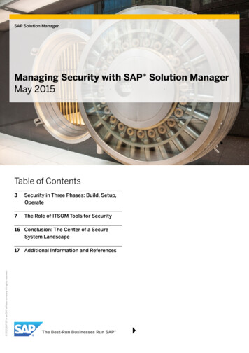
4 pin Auxiliary/Pin switch Monitor HarnessBLACK/WHITE(-) 200 mA FLEX 2 OUTPUT (DOME LIGHT SUPERVISION)BLUE/BLACK(-) 200 mA FLEX 1 OUTPUT (2nd UNLOCK)GRAY(N/O or N/C) HOOD TRIGGER INPUTBLUE(-) TRUNK/MUX TRIGGER INPUTBLACK/WHITE (-) 200mA FLEX 2 OUTPUTFrom factory this output is used for a dome light supervision relay, this output can be programmed for otherfunctions (see features programming table/descriptions for options and how to activate with an add-onsecurity system).Important! This output is only intended to drive a relay. It cannot be connected directly to a high currentdevice.[Optional connection for both configurations]BLUE/BLACK (-) 200mA FLEX 1 OUTPUTFrom factory this output is used for optional progressive unlock, A progressive unlock system unlocks thedriver’s door when the unlock button is pressed and unlocks the passenger doors if the unlock button ispressed again within 15 seconds after unlocking the driver’s door. This output can be programmed for otherfunctions (see features programming table/descriptions for options and how to activate with an add-onsecurity system).Important! This output is only intended to drive a relay. It cannot be connected directly to a high currentdevice.[Optional connection for both configurations]GRAY (N/O or N/C) HOOD TRIGGER INPUTConnect to a wire that changes state when the hood is opened. N/O rests at ground when the hood isOPEN, N/C rests at ground when the hood is CLOSED (see features programming table for options).[Optional connection for both configurations]BLUE (-) TRUNK/MUX TRIGGER INPUTConnect to a wire that goes to ground (-) when the trunk is opened or to the pre-trigger and full triggeroutputs of an optional Directed Electronics dual zone sensor. This wire is also used for sensor shunt whenadding an optional remote start. See diagram below for sensor shunt wiring information.To Trunk pin invehicle (if used)Trunk Pin Input(-) Status OutputFlex Output(-) Activation InputIgnition InputIgnition OutputALARM MODULEREMOTE STARTMODULE[Optional connection for both configurations]8 2012 Directed. All rights reserved.
3 pin Door Lock HarnessGREEN(-) 200mA LOCK OUTPUTEMPTYNOT USEDBLUE(-) 200mA UNLOCK OUTPUTGREEN (-) LOCK OUTPUTConnect to a wire that pulses ground to activate the vehicle door lock relay. (Usually at the door lock switchor BCM).[Optional connection for both configurations]BLUE (-) UNLOCK OUTPUTConnect to a wire that pulses ground to activate the vehicle door unlock relay. (Usually at the door unlockswitch or BCM).[Optional connection for both configurations]NOTE: For door lock wiring diagrams refer to document #1041 under the Resources tab at www.directechs.com5 pin RKE (Remote Keyless Entry) HarnessGRAY/BLACK( ) OEM TRUNK SHUNT INPUTRED/BLACK( /-) DISARM DEFEAT INPUTRED( ) DISARM INPUTGREEN/BLACK( /-) ARM DEFEAT INPUTDARK GREEN( ) ARM INPUTGRAY/BLACK ( ) TRUNK SHUNT INPUTConnect to a wire that pulses ( )12V when the OEM trunk release is activated. If the system is armed whenthe trunk is opened with the OEM remote, the shock sensor and trunk trigger will be bypassed until the trunkis closed. See diagram below for sensor shunt wiring information.NOTE: The blue (-) trunk pin input must be connected for feature to work correctly.ALARM MODULEGRAY/BLACK ( )Shunt InputBLUE (-)Trunk Pin InputTo Trunk PinTrunk ReleaseSolenoid( ) Trunk ReleaseMotor WireTo BCM/Control Relay[Optional add-on security connection] 2012 Directed. All rights reserved.9
RED/BLACK ( /-) DISARM DEFEAT INPUTConnect to a wire that pulses ( ) 12V OR ground when ALL doors unlock (usually the passenger door motoror driver door unlock switch). Disarming will be defeated if this wire receives a pulse simultaneously withthe Disarm input. This is a polarity selectable input, (see features programming table for options).[Required add-on security system connection]RED ( ) DISARM INPUTConnect to a wire (usually the driver door motor) that pulses ( ) 12V when the driver door unlocks using theOEM remote to disarm the system. This wire triggers the Disarm command for the system.[Required add-on security connection]GREEN/BLACK ( /-) ARM DEFEAT INPUTConnect to a wire that pulses ( ) 12V OR ground when the doors lock (usually the driver door lock switch).Arming will be defeated if this wire receives a pulse simultaneously with the Arm input. This is a polarityselectable input, (see features programming table for options).[Optional add-on security connection]DARK GREEN ( ) ARM INPUTConnect to a wire (usually the driver door motor) that pulses ( ) 12V when the doors lock. This wire triggersthe Arm command for the system.[Required add-on security connection]Light flash Polarity SettingThe internal fuse is used to determine the light flash output. In the ( ) position, the on-board relay outputs ( )12V on the WHITE wire. In the (-) position, the on-board relay will supply a (-) output. When wiring into amultiplex circuit, you can replace the fuse with a resistor (paying attention to the polarity setting). (Refer todiagram on White/ Black wire description).Note: For parking light circuits that draw 10-amps or more, the internal jumper must be switched to a (-)light flash output. P/N 8617 or a standard automotive SPDT relay must be used on the light flash outputwire.Light FlashPolarity Jumper DetailLIGHT FLASH POLARITY(10A (MAXIMUM) FUSE JUMPER)Note: Replace fuse with specified resistor valueif connecting to multiplex light circuit(paying special attention to polarity selection).[Required connection for both configurations]10 2012 Directed. All rights reserved.
Programming System FeaturesThe System Features Learn Routine dictates how the unit operates. It is possible to access and change any ofthe feature settings using the Valet button. However, this process can be simplified by using the Bitwriter.Note : The Bitwriter requires chip version 2.8 or newer to program this unit.To program features:1. Open a door, turn the ignition on and then off2. Press/release the Valet button the number of times corresponding to the menu item number and featureyou wish to change in Feature Menu table below and then press/hold3. The horn/siren sounds and the LED flashes the specified number to confirm the selected item.4. The button can be released (Exit in 30 seconds if no action is performed)5. Select the option by pressing the Arm/Disarm buttons of a programmed dealer master or consumerremote control. Pulsing 12V on the Arm input wire selects options when a remote has not been programmed6. The horn/siren sounds and the LED flashes to indicate the selected option7. To save the option and select the next menu item to program - return to Step 2 above.8. To exit turn the ignition on, the horn/siren sounds twice to confirm.NOTE: When installed as an Add-on Security System or an Add-on Sensor System; pressing the Lock/Unlock buttons of the OEM Remote selects options as in Step 5 above.The learn routine Exits if any of the following occurs: The open door is closed The ignition is turned on There is no activity for 30 seconds The valet button is pressed too many timesFeature MenuMenuItemFeatureOption 1Option 21Security FeaturesOn*(Off)2Arming TypeActive*Passive-no lock3Arm/Disarm chirpsOn(Off)*4Ignition control locksNo ignition locks*Lock and unlock5PanicOn*(Off)6Hood Trigger typeNormally OpenNormally Closed7Horn functionSiren(Horn 10 ms)8Door trigger error chirp(On)Off9Door lock output(0.8sec)3.5 sec10Arm defeat polarity(Positive)Negative11Disarm defeat polarity(Positive)Negative12**Option 3Option 4Option 5(Passive-lock)Lock onlyUnlock onlyHorn 20 msHorn 40 ms0.4 sec.double unlock (0.4sec)Horn 50 msSensor Add Arming TypeActive(Passive)13Flex Output 1Domelight Supervision(Factory AlarmDisarm)2nd unlockFactory AlarmTriggerRemote StartReport14Flex Output 2(Domelight Supervision)Factory AlarmDisarm2nd unlockFactory AlarmTriggerRemote StartReport15OEM Alarm ArmingInstantDelay**This feature does not apply to this system 2012 Directed. All rights reserved.11
Table Notes:1. Items 1-5 * indicates default Consumer mode options when changed to a Consumer mode of operation. Anychanges must be made after the system is set to Consumer mode. BOLD type indicates Dealer Security mode default settings when a Dealer Master Remote has beenprogrammed to the system.2. Items 6-14 These options are specific to the vehicle interface and remain as programmed when the system ischanged to Dealer mode or Consumer mode.3. Quick access: To turn on the honk/chirp feature without entering programming; simply turn on the ignition and pressand hold the Valet button, the unit will respond with a single honk/chirp when turning the featureON. To turn off the honk/chirp feature follow the above steps, the unit will respond with a double honk/chirp when turning the feature off.Feature Descriptions (consumer factory default settings are in bold)Security Features: On: The main unit will monitor all alarm zones and trigger as normal when activated. Off: Trigger zones will be ignored when armed and will not trigger if activated (convenience functions still operate as normal)Arming Type: Active: the remote must be used to arm the system Passive Arm w/o lock: after exiting the vehicle the system will automatically arm. The doors will notlock Passive Arm w/lock: after exiting the vehicle the system will automatically arm and lock the doorsNote: In consumer mode; passive arming occurs 60 seconds after the door is closed. in dealer mode;passive arming occurs 30 seconds after after the door is closed.Arm/Disarm Chirps: On: arm, disarm, and sensor warn-away chirps are active Off: arm and disarm chirps are defeated, warn-away chirps are activeIgnition Controlled Locks:No Ignition-locking: the door lock/unlock outputs will not activate when ignition is turned on/offLock & Unlock: the door lock & unlock output will activate when ignition is turned on & offLock Only: the door lock output will activate when ignition is turned onUnlock Only: the door unlock output will activate when ignition is turned offPanic: On: the Panic output can be activated at any time Off: the Panic output is defeatedHood Trigger Type: Normally Open: for vehicles with a hood switch that rests at ground when the hood is OPEN Normally Closed: for vehicles with a hood switch that rests at ground when the hood is CLOSEDHorn Function: Siren Function: The horn output will emulate the siren output when arming/disarming and will stayon constant for panic/trigger outputs Horn Function 10/20/40/50ms: The horn output will pulse for the selected duration when arming/disarming and pulse 600ms on/600ms off during panic/trigger outputs12 2012 Directed. All rights reserved.
Door Trigger Error Chirp: On: if the door trigger is active when arming, the horn/siren will emit an additional sound as analert notification Off: an active door trigger when arming will not create an alert outputDoor Lock Output: 0.8 seconds: the door lock output pulses will be 800ms in duration 3.5 seconds: the door lock pulses will be 3.5 seconds in duration 0.4 seconds: the door lock pulses will be 400ms in duration Double Unlock (0.4 seconds): the unlock output only will pulse twice and will be 400ms in durationArm Defeat Polarity(for add-on security setting): Positive: Arm defeat wire requires a positive pulse to defeat the arm operation Negative: Arm defeat wire requires a negative pulse to defeat the arm operationNote: in both options above the Ignition Override will also be functionalDisarm defeat polarity (for add-on security setting): Positive: Disarm defeat wire requires a positive pulse to defeat the disarm operation Negative: Disarm defeat wire requires a negative pulse to defeat the disarm operationSensor Add Arming Type (for sensor-add setting): Active: requires same activation input on door motor wires as RKE security to arm the sensor Passive: sensor arms by timer duration after the ignition is turned off and vehicle is exited.Note: This feature does not apply to this system.Flex Output 1: Dome light: The output will turn on for 30 seconds (or until the ignition is turned on) each time thesystem is disarmed. If on, it will turn off if the system state changes from disarmed to armed. FAD (Factory Alarm Disarm): The output will pulse once for 800ms when disarming or activatingthe trunk release. The disarm pulse will begin 500mS before the unlock or trunk release outputbegins. 2nd unlock: The output will pulse for 800ms upon the 2nd Disarm command from a remote. It willalso pulse when ignition is turned off for ignition controlled unlocking;only if the user activated theAUX2nd unlock output prior to entering the vehicle. FAT (Factory alarm trigger): The output will pulse once for 800ms when the on-board shock sensordetects a full trigger. This setting is used whenadding this system to a vehicle to trigger the factoryAUXalarm.button on the remote is Remote Start Report: The output will pulse once for 800ms when thepressed OR when pressing the LOCK button on the OEM remote twice.AUXAUXNOTE: when programmed for remote start report thebutton will no longer control the panic feature,button on the remote for 3 seconds.panic will be controlled by pressing theFlex Output 2: Dome light: The output will turn on for 30 seconds (or until the ignition is turned on) each time thesystem is disarmed. If on, it will turn off if the system state changes disarmed to armed. FAD (Factory Alarm Disarm): The output will pulse once for 800ms when disarming or activatingthe trunk release. The disarm pulse will begin 500ms before the unlock or trunk release outputsbegin. 2nd unlock: The output will pulse for 800ms upon the 2nd Disarm command from a remote. It willalso pulse when ignition is turned off for ignition controlled unlocking; only if the user activated the2nd unlock output prior to entering the vehicle. FAT (Factory alarm trigger): The output willpulse once for 800ms when the on-board shock sensorAUXdetects a full trigger. This setting is used when adding this system to a vehicle to trigger the factoryalarm. Remote Start Report: The output will pulse once for 800ms when the button on the remote ispressed OR when pressing the LOCK button on the OEM remote twice.NOTE: when programmed for remote start report thebutton will no longer control the panic feature,panic will be controlled by pressing the button on the remote for 3 seconds.AUXAUX13 2012 Directed. All rights reserved.AUX
OEM Alarm Arming (for add-on security system setting) Instant: When Armed by a pulse on the Arm input, the arming operation will be same as using aTX to arm. Delay: When Armed by a pulse on the Arm input, the arming operation will have a 30 second Ignition Override timer before fully arming. If the Ignition is turned on before the end of the 30 secondsthe system will disarm.Remote Control Programming and Deletion1. Open a door and turn the ignition on .2. Press/release once and then press/hold the Valet button (one horn/siren sound confirms selection) orpress/release twice and then press/hold to delete remote controls (two horn/siren sounds confirms selection).3. The button can be released (Learning exits in 30 seconds).4. Press/hold the remote controlbutton until the transmit LED turns on solid (10 seconds) or if deleting allbutton of a programmed remote.remote controls press the5. The horn/siren emits one sound to confirm. If deleting the Dealer Master Remote press and hold the "insert unlock icon" button until the transmit LED turns on solid (10 seconds)6. Repeat for each Consumer remote to be learned (up to four). For additional Dealer Master Remote controls, enter the same code of the original Dealer Master Remote that has already been programmed tothe system.7. Turn the ignition off or wait 30 second to exit learning, the horn/siren emits 2 sounds to confirm.AUXAUXNote: If consumer remotes have been programmed to the system the main unit will be placed in dealermode by programming a Dealer Master Remote to the system. However, if a Dealer Master remote hasbeen programmed, it must be deleted before the system will accept the Consumer remotes.Menu Table:Item1 sound/flash2 sounds/flashesFunctionAuto learn new remoteDelete all remote controlsBasic Remote Functions TablePress and ReleaseButtonShift (Press/Press/Holdrelease “AUX”for 2 secs.first)ArmSilent ArmArm and PanicDisarmSilent DisarmNo FunctionNo FunctionTrunk releaseCar FinderPanic ononAUXAUXAUXAUXAUXAUXShift andAUXSensorBypassAUXOptional RemoteStarterNOTE: See Owner/Dealer Master Remote Guide for more details14 2012 Directed. All rights reserved.
System Testing and Impact Sensor AdjustingRF Security SettingArming1. Press the button on the remote2. Doors lock, Lights flash and the horn/siren sounds once For silent arming; press the AUX button prior to pressing the button.3. Dome light turns off, starter kill becomes active, and the status LED begins flashing.4. While arming, the system tests the trigger inputs for status. If any trigger inputs are active when armingthe horn/siren sounds a second time as a notification, both the onboard impact sensor and the activeinput are bypassed. The open zone is bypassed until corrected and the impact sensor is bypassed fora maximum of 4 minutes. While bypassed, the active input is indicated by the status LED flashes (seetable of zones for LED flashes).5. Sensor testing:a. Gently impact the vehicle with increasing intensity to test the pre-trigger level (10 horn/siren sounds.b. Impact that location more heavily to test the full-trigger level (horn/siren/lights for 30 sec.)c. Adjust the sensor pot until the desired levels are obtainedNote: The Nuisance Prevention feature bypasses the sensor after three full-triggers; to reset if active,disarm the system and turn the ignition on/off.6. Protected entry tests: Open each door, the horn/siren sounds quickly and then begin the full-trigger output Open the hood or trunk, or turn on the ignition to immediately begin the full-trigger output.Note: The Nuisance Prevention feature bypasses an input that stays active for three full-triggers; close theinput to reset.AUXAUXSensor Bypass1. Press and release the AUX button within 5 seconds after button, the lights flash two times and thepre-trigger output is bypassed2. Press and release the AUX button again within 5 seconds, the lights flash three times and the pre-trigger and full-trigger outputs are bypassedbutton anytime to reset the sensor3. Press theAUXDisarming1. Press thebutton2. Doors unlock, Lights flash and the horn/siren sounds two times. If the system has been triggered, thehorn/siren sounds four times or five times if the sensor is bypassed For silent disarming; press the AUX button prior to pressing thebutton.3. Dome light turns on, starter kill becomes inactive, and the status LED turns off. If triggered, the status LED continues to flash to indicate triggered inputs (see table of zones). Turnon the ignition to reset the LED.4. Press thebutton again to unlock the passenger doors if 2nd unlock is connectedAUXAUXAUXTrunk Release1. Press and hold the AUX button2. Factory alarm will disarm if the output is connected3. Trunk opensAUXNote: If the systemis armed, the trunk input and sensor is bypassed until the trunk is closed. Trunk shuntbypass requires the Blue trunk trigger input to be connected to the vehicle to bypass when armed (see Bluewire AUXdescription for wiring information).AUXAUXAUXPanic1. Press and hold thebuttonAUX2. The lights flash and the horn/siren sounds for 30 seconds.orbuttons to reset3. Press the ,AUXCar Finder1. Press and release the AUX button prior to pressing thebutton2. The horn/siren emits one sound and the lights flash 10 timesorbuttons to stop the feature.3. Press theAUXAUX 2012 Directed. All rights reserved.AUXAUX15
OEM Security SettingArming1. Press the Lock button on the OEM remote2. Doors lock, lights flash and the horn/siren sounds once, starter kill becomes active, and the status LEDbegins flashing.3. While arming, the system tests the trigger inputs for status. If any trigger inputs are active when armingthe horn/siren sounds a second time as a notification, both the onboard impact sensor and the activeinput are bypassed. The open zone is bypassed until corrected and the impact sensor is bypassed fora maximum of 4 minutes. While bypassed, the active input is indicated by the status LED flashes (seetable of zones for LED flashes).4. The shock sensor is enabled after a one minute delay.Note: The system can be disarmed if the ignition is turned on during this one minute delay (see featuresprogramming table for options).5. Sensor tests, adjustments, and protected entry tests are the same as for an RF Security System.Arming defeat1. Press the driver door lock switch.2. The system does not arm if the Arm Defeat
This wire should be connected to the parking light wire in the vehicle. See setting the light flash polarity sec-tion of this guide for polarity settings. Note: For parking light circuits that draw 10 amps or more, the internal jumper must be switched to a (-) light flash output. (See setting the light flash polarity section of this guide.)