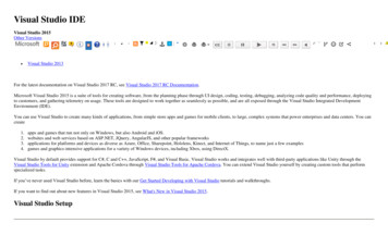
Transcription
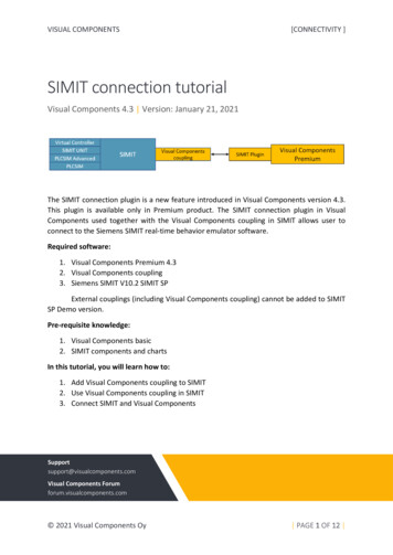
VISUAL COMPONENTS[CONNECTIVITY ]SIMIT connection tutorialVisual Components 4.3 Version: January 21, 2021The SIMIT connection plugin is a new feature introduced in Visual Components version 4.3.This plugin is available only in Premium product. The SIMIT connection plugin in VisualComponents used together with the Visual Components coupling in SIMIT allows user toconnect to the Siemens SIMIT real-time behavior emulator software.Required software:1. Visual Components Premium 4.32. Visual Components coupling3. Siemens SIMIT V10.2 SIMIT SPExternal couplings (including Visual Components coupling) cannot be added to SIMITSP Demo version.Pre-requisite knowledge:1. Visual Components basic2. SIMIT components and chartsIn this tutorial, you will learn how to:1. Add Visual Components coupling to SIMIT2. Use Visual Components coupling in SIMIT3. Connect SIMIT and Visual l Components Forumforum.visualcomponents.com 2021 Visual Components Oy PAGE 1 OF 12
ContentsIntroduction. 2Adding VC coupling to SIMIT . 3Using Visual Components coupling in SIMIT . 4Connect SIMIT plugin and VC coupling . 8Limitations . 12IntroductionThe communication between VC and SIMIT is achieved using two software components. Visual Components coupling. An external coupling for SIMIT, also called “VC coupling”for short.SIMIT Connection plugin for Visual Components Premium application, or “SIMITplugin” for short.Both are developed by Visual Components and are only meant to be used with correspondingversions of each other.NOTE: This tutorial is limited to show the connectivity between Visual Components andSIMIT. Creating charts in SIMIT software and connectivity between other SIMIT couplingsare not shown.[SIMIT Plugin Tutorial] PAGE 2 OF 12
Adding VC coupling to SIMIT1. In the PC in which SIMIT software is installed, go to this path, C:\Program Files(x86) \Siemens\Automation\SIMIT\SIMIT SF2. Create folder called couplingsThe coupling’s folder under “couplings” defines the name of the coupling in SIMIT software.This name is significant, because it is used as part of the identifier for coupling signals andsignals used in SIMIT charts. So, if the coupling folder name is changed, references to itssignals will break.3. Download the VC coupling from Visual Components downloads allers/VisualComponents/addons/SIMIT/Visual Components SIMIT coupling.zip4. Extract the Visual Components SIMIT coupling.zip file. You will have VisualComponents folder. This folder contains necessary files for VC coupling.5. Move the extracted Visual Components folder to the couplings folder. You mayalso want to define a shorter coupling name than “Visual Components” becausethe signals in SIMIT charts show this coupling name first and then the signalname if there is space. For example, change the folder name to “VC”[SIMIT Plugin Tutorial] PAGE 3 OF 12
Using Visual Components coupling in SIMIT1. Launch SIMIT SP application and create a new project. SIMIT SP Demo does notallow to use external couplings.2. From the Project navigation, under your project expand Couplings folder. Right-clickon New coupling and select New coupling (or double-click on New coupling)3. This will open the Selection window. Select VC under Extern and click OK. If you havenot changed the folder name in couplings folder, then instead of VC you will haveVisual Components as the SIMIT coupling name.[SIMIT Plugin Tutorial] PAGE 4 OF 12
4. The added Visual Components coupling is shown under Couplings.In the SIMIT property view you can find Visual Components coupling propertiesTime slice – Value is the time slice from project properties. There are 8 available timeslices for a project. The communication is asynchronous, signal exchange with thecoupling should have minimal effect on the real-time execution of your SIMITsimulation.Configuration Server Port and Runtime Server Port – Ports used to connect to VisualComponents applicationCoupling Version – Visual Components coupling versionNOTE: Configuration server needs to restart when its port number is changed, whichcauses any connected VC clients to lose connection[SIMIT Plugin Tutorial] PAGE 5 OF 12
5. To add signals in VC coupling, click on Open Editor to open Coupling Signal EditorwindowCoupling Signal EditorSignal name – The name should be unique and not blankData type – Accepted simit signal data types are Binary, Integer and Analog (doubletype)Direction – Signal values are transferred- To SIMIT – Input signals to SIMIT from Visual ComponentsNOTE: These are SimulationToServer variables in Visual Components- From SIMIT – Processed output values from SIMIT to Visual ComponentsNOTE: These are ServerToSimulation Variables in Visual ComponentsInitial value – Initial value for the signal assigned at SIMIT simulation startDescription – Description for the signal[SIMIT Plugin Tutorial] PAGE 6 OF 12
To create coupling signal:1.2.3.4.5.6.Enter the Signal nameSelect data typeChoose directionSet initial valueWrite descriptionHit EnterNOTE: If any cell value is left empty, it will use default values when you close theeditor. Also, the names are automatically made unique when you close the editor.7. Close the Coupling Signals Editor8. Click ‘Yes’ to create/update the signal namesUnder Inputs you will have the “From SIMIT” direction signals and under Outputs you willhave the “To SIMIT” direction signalsYou can find the defined signals under Search results.[SIMIT Plugin Tutorial] PAGE 7 OF 12
NOTE: Whenever you add/remove/modify signals in signal editor, click ‘Save’ icon to savethe changes.Connect SIMIT plugin and VC coupling1. Enable the ‘’Connectivity” addon from the Visual Components Premium backstageand restart the application. In the Connectivity Configuration, select SIMIT and AddServer2. From the Edit Connection panel,Address – Enter the IP address of the machine in which the SIMIT environment isrunning.SIMIT port – The Configuration Server port defined in the VC Coupling.Timeout – in Milliseconds. Used for initial connect and asynchronous operations.[SIMIT Plugin Tutorial] PAGE 8 OF 12
Select “Test connection” and check if it succeeds. Select “OK”Select Apply to set the SIMIT plugin connection properties.NOTE: Both cyclic and event-based update modes are supported, and the communication isalways asynchronous.In the future, if you want to edit the server, from the Server properties panel, select “EditConnection ”[SIMIT Plugin Tutorial] PAGE 9 OF 12
3. Connect the SIMIT plugin server. This will display the “From SIMIT” and “To SIMIT” inthe Create Variable Pairs panelNOTE: If you make any changes in the VC Coupling in the SIMIT environment, right-click on anempty space from the Server structure and select “Reload Server Structure”[SIMIT Plugin Tutorial] PAGE 10 OF 12
4. Select the variable group, “Simulation to server” or “Server to Simulation”. Select thevariables to be paired and click “Pair Selected” .5. “Start” the simulation in SIMIT application.6. Start the simulation in Visual Components application.You can see the value changes for the signals paired between Simulation to Server and ToSIMIT and signals paired between Server to simulation and From SIMIT[SIMIT Plugin Tutorial] PAGE 11 OF 12
Limitations One coupling per project: Users should only add one instance of the VisualComponents coupling to a SIMIT project.Signals must be defined in the Visual Components coupling in SIMIT software: Thesignals to be exchanged with Visual Components SIMIT plugin must be explicitlydefined in the SIMIT VC Coupling and then connect to the charts.[SIMIT Plugin Tutorial] PAGE 12 OF 12
2. Visual Components coupling 3. Siemens SIMIT V10.2 SIMIT SP External couplings (including Visual Components coupling) cannot be added to SIMIT SP Demo version. Pre-requisite knowledge: 1. Visual Components basic 2. SIMIT components and charts . In this tutorial, you will learn how to: 1. Add Visual Components coupling to SIMIT 2.