Transcription
International Journal of Current Engineering and Technology 2016 INPRESSCO , All Rights ReservedE-ISSN 2277 – 4106, P-ISSN 2347 – 5161Available at http://inpressco.com/category/ijcetResearch ArticleDesigning and Optimization of Wheel Assembly of a Formula StudentCarJoijode Vrushabh Umesh†* and Yadav Abhishek††MechanicalEngineering Department, Vishwakarma Institute of Technology, 666, Upper Indira Nagar, Pune-37, IndiaAccepted 02 March 2016, Available online 15 March 2016, Special Issue-4 (March 2016)AbstractIn a Formula Student Car or in any car as such, the part that connects the main frame of the body with the wheelsthrough suspension arms is known as the Wheel Assembly. It is a part of the Final drive as well. While designing anddeveloping any automobile the designing of the wheel assembly is critical. It is due to the reason that a lot of forcesare acting on the wheel assembly during accelerating, braking, cornering and tilting. Furthermore, the WheelAssembly is an important part of an automobile and its failure is hazardous endangering human life. Therefore isrequired to design the Wheel Assembly and its components considering all the factors leading to the failure bydeveloping a safe Design. It must also be noted that, the components must be designed in such a way that they have aminimum weight at the same time care must be taken that they do not cross a certain limit of stress value. In thisPaper the Complete Design Procedure of the Wheel Assembly for R12 Rims with wet Tires (165 60) has beenpresented along with optimization of the same components. The weight of the Vehicle is considered to be 300 kgalong with the driver. The paper illustrates the forces acting on the components, the failure criteria and theoptimization of the components. Optimization has been carried out by doing analysis of the components in Hypermesh. The paper deals with finding out the dimensions of the individual components and also detecting the probableregions of stress concentration. The Wheel Assembly designed in the paper is of Team Veloce, VIT, Pune. The designprocedure follows all the rules laid down by FSAE Rule Book for Formula Type Cars.Keywords: Yield Strength, Factor of safety, Load transfer, stress concentration, mesh, element size, analysis.1. Introduction1 Anautomobile is said to function appropriately onlywhen all its systems are working as they are requiredto work. The engine produces power and gives it to thedrive train through a clutch. The portion of the drivewhich transmits this power from the drive train to thewheel and which connects the main frame of the bodywith the wheels through the suspension arms isknown as the Wheel Assembly. It is a part of the finaldrive. Thus it serves the function of transmitting thepower from the drive shaft to the wheels. Besides asthe suspension arms are also connected to it, thewheel assembly also transfers the bump force from theground to the suspension arms.There are always two types of masses in anautomobile – sprung and unsprung mass. All the massof the vehicle that is damped by the spring is called asthe sprung mass. As the Wheel Assembly mass is notdamped by the spring, it comes into the unsprungmass category. We know that the unsprung mass mustbe lower than the sprung mass and also should be asleast as possible to provide proper drive stability andload balancing of the vehicle. Thus it becomesimportant to reduce the mass of the wheel assemblyand the rims and tires. But while doing this care mustbe taken that the mass of the wheels, tires and thewheel assembly must be enough to prevent the lateraltoppling of the vehicle at the time of cornering orimpact.There are a lot of forces acting on the wheels in thestatic and especially in the dynamic condition. As theWheel assembly is directly connected to the wheels, allthese forces also have an impact on the designing ofthe Wheel Assembly. A lot of forces act on the wheelassembly during accelerating, braking, cornering andtilting.A good Wheel Assembly is one which can sustainsuch forces over a longer period of time. Thus it isrequired to design the wheel assembly considering allthese factors. A failure of any component of the WheelAssembly means a breakdown of the automobile andin some cases might also be hazardous for the driver.Thus utmost care must be taken while designing theWheel Assembly. The objective of Optimization is*Corresponding author: Joijode Vrushabh Umesh307 MIT College of Engineering, Pune, India, AMET 2016, INPRESSCO IJCET Special Issue-4 (March 2016)
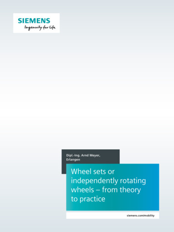
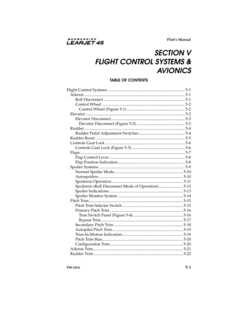
Joijode Vrushabh Umesh et al.Designing and Optimization of Wheel Assembly of a Formula Student Caralways to find the best possible and suitabledimension. This is because optimization does notalways mean reducing dimensions it also meansfinding out the dimensions which will just enough tosustain the forces.Here in this case, R12 rims have been used along with165 60 wet tires. The Weight of the vehicle isconsidered to be 300 kg along with the driver. All theforces have been found out on the above basis andaccording to the above mentioned Wheels. The WheelAssembly designed in the paper is of Team Veloce, VIT,Pune. The design procedure follows all the rules laiddown by FSAE Rule Book for Formula Type Cars.The analysis is done on Hyper works.While generating the mesh proximity and curvaturefeature is used which is used to generate more amountof nodes at bends and cavities.The above feature is helpful as stress concentrationtends to accumulate more in regions of bends andcavities.Table 1 Parameters of mesh elementsParameterSizeMinimum Element Size0.4mmFeature Angle30Element Size2mmThe mesh generated is a tetra mesh.99% and above of all the elements generated in themeshing pass the following parameter.2. Components of Wheel Assembly.As shown in the figure the Wheel Assembly consists ofthe following 1)Bearingsa. Taper Roller Bearing- Front-(2)b. Deep Groove Ball Bearing-Rear-(1)Nut-(1)Cotter/Split Pin-(1)Before understanding the procedure it is important tounderstand how all these components are assembled.Firstly the spindle is take. The Knuckle is press fittedon the spindle. Then the spacer between the knuckleand hub is either slide fitted of r press fitted on thespindle in order to accommodate the caliper. Afterwards the inner race of the bearing is press fitted onthe spindle. The hub is taken and the outer race of thebearing is press fitted in the hub. Then the hub ispositioned on the bearing and then the secondbearing’s inner race is press fitted on the spindle. Thenthe nut is tightened on the spindle and a split pin isinserted into the hole made in spindle for positivelylocking the Wheel Assembly.Table 2 Element type2D TypeTrias3D TypeTetrasElements generated after meshing are checked underthe following parameters:Table 3 Checking ParametersAspect 5.00Warpage 5.00Skew 60.00Tet. Collapse 0.2Cell Squish 0.5Jacobian 0.7Fig.1 Wheel Assembly View-1Fig.2 Wheel Assembly View-2308 MIT College of Engineering, Pune, India, AMET 2016, INPRESSCO IJCET Special Issue-4 (March 2016)
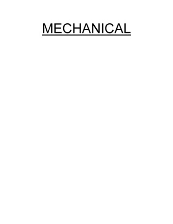
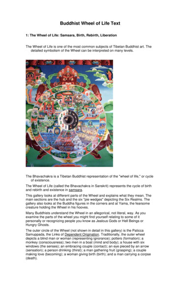
Joijode Vrushabh Umesh et al.Designing and Optimization of Wheel Assembly of a Formula Student CarFig.4 Front Suspension GeometryFig.3 Exploded View3. Design ProcedureThe following paper deals with the design procedureof the wheel assembly. Designing the wheel assemblyis nothing but deciding the shape according to therequirement, finding out the dimensions of the variouscomponents, their position in the wheel assembly, thetype of fit between the components, etc. The followingare the steps in designing the Wheel assembly:-Fig.5 Rear Suspension Geometry3.1 Getting the prerequisite parameters from thesuspension and steering geometryThe first step while designing the wheel assembly is tofind out the required parameters in order to design thewheel assembly from the steering and the suspensiongeometry. The Steering and Suspension Engineerdesign their geometry, a kinematic representation ofvarious parts in that system, according to therequirement. A Wheel Assembly Design Engineer mustrefer to these geometries so that in the actual car theseparameter are followed. The Steering Geometry has aninfluence on the Front Wheel Assembly only. TheFront Suspension and Rear Suspension Geometryaffect the front and rear assemblies. Parameters suchas King Pin Angle, Steering Arm angle, Tie rod angleare obtained from the Steering geometry, whereas theCaster angle, the angle of upper A-arm and the lowerA-arm, Rear Track width are obtained fromSuspension Geometry. Parameters like the Stub lengthand the front track width are obtained from bothGeometries. Considering the Front Wheel Assemblythe Parameters are as followsFig.6 Steering Geometry3.2 Finding the effect length of knuckleThe lengths of the knuckle obtained from thesuspension geometry is from one view only. Besides itis a matter whether or not to provide inbuilt casteralso affect the length. So it is important to find out theactual lengths from these two angles as shown infigure. From the above figure it is clear that theeffective length of the front knuckle is 85.685 aboveand 86.761 from the center point.Total Effect Length: - 172.411mmKing Pine Inclination:-70Caster Angle: - 50Tie Rod Angle: - 3.940Track Width: - 1200mmWheel Diameter: - 502.8mmTotal length of Knuckle: - 171mmUpper A-arm angle: - 6.3690Lower A-arm angle: - 3.1930Fig.7 Effect of King Pin and Caster on Length309 MIT College of Engineering, Pune, India, AMET 2016, INPRESSCO IJCET Special Issue-4 (March 2016)
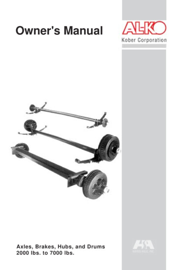
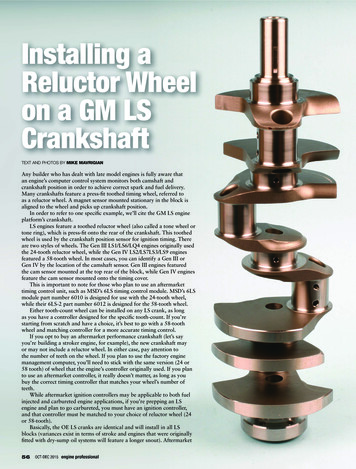
Joijode Vrushabh Umesh et al.Designing and Optimization of Wheel Assembly of a Formula Student Car3.3 Design of Spindle 75 9.81 Firstly the spindle is designed on which othercomponents such as knuckle, bearings and hub will befitted. At this stage we cannot decide the actual lengthof the spindle, so we just consider the tentative lengthof the spindle.Material: - The material for manufacturing the spindleis taken to be EN24. There will be parts which will bepress fitted on the spindle. So heat treatment will benecessary to increase surface hardness. Besides theyield strength in tension of EN24 is also high.Syt 654 N/mm2 [4] 0.7 129.44 NTorque on spindle 130 N3.3.2(i)Drawing the Free Body DiagramDrawing the Free Body Diagram (FBD) gives an ideaabout the forces acting on the componentsimultaneously.Endurance Limit 412 N/mm2 [4]It consists of following steps: 3.3.1Determining the forces acting on the spindle:The forces acting on the spindle are as followsa.Weight of the vehicleDuring static and dynamic conditions a constant forceof the self-weight is acting on the spindle at the partinside the knuckle. Even if it is considered as the morethan half the weight of the car is acting at the frontportion of the car during braking, the weight on theone wheel isFig.8 Free body Diagram3.3.3Designing and determining the dimensions.Shear Failure of the SpindleThe spindle is likely to fail in shear because of thebump force. The spindle is a critical part and it is not atWeight in the front portion 175 kgall desirable to fail any condition, hence the factor ofWeight on one tire 175/2 87.5 kgsafety is taken to be 3.Force due to weight of the vehicle 87.5 9.81 858.375 NThe allowable shear stressLet us consider this weight to be 1000 N.b. 109N/mm2Now,Bump force on the tireAt the time of a bump in the surface a force will act onthe portion of the spindle which is inside the spindle.This is because the hub is bolted directly to the wheel.This force is obtained from the wheel rate. For designpurpose the wheel rate is kept as 45N/mm2. Also it isconsidered that there will be no bump more than30mm as the track is extremely flat.Bump Force Wheel rate Travel due to bump 45 30 1350 Nc.Torque on the spindle.Torque mass on the spindle g radius of the wheel coefficient of frictionThus from the shear failure the diameter ofspindle-‘d’ comes out to be 4 mmBending and Torsional Failure of the SpindleTo find out the Maximum Bending Moment, the SFDand BMD are to be drawn. Referring to the forcediagram of the spindle,310 MIT College of Engineering, Pune, India, AMET 2016, INPRESSCO IJCET Special Issue-4 (March 2016)
Joijode Vrushabh Umesh et al.Designing and Optimization of Wheel Assembly of a Formula Student CarThe Torque acting on spindle can be directly takenfrom result number (i)Mt 130 N-m 130000N-mmAs EN24 is a ductile material, using maximum shearstress theory to find out the diameter of the spindle.d3 d3 [1] d 18.35 mm20 mmThus from the bending and torsional failure thediameter of spindle-‘d’ comes out to be 20 mm3.3.4Analysis and Optimization.Fig.9 Shear Force Diagram and Bending MomentDiagramEquating forces along Y-axis to 0Ra Rb 1000-1350Ra Rb - 350 NEquating the moments about point A 0- (1350 15) – (Rb 30) (1000 55) 0Rb 1158.33NRa 1158.33N - 350 NRa -1508.33NAfter reconsidering the force diagram comes out be asshown in figureNow,Moment about D 0Moment about B (1000 25) 25000 N-mmMoment about C (1000 40) – (1160 15) 22600N-mmMoment about A (1000 550) – (1160 30) – (1350 15) -50 N-mmFrom above it is clearly seen that the maximumbending moment is at point B, thus Mb 25000N-mmFig.10 FEM Analysis of Spindle3.4 Design of KnuckleKnuckle is that part of the wheel assembly which ispress fitted on the spindle and the A-arms are alsomounted on the Knuckle. Besides the knuckle alsoserves the function of providing mounting to the BrakeCaliper. The Steering Arm which is used to connect thewheel assembly and the tie rod is also mounted on theknuckle. Thus due to all these mountings, there are alot of forces acting on the knuckle. The Knuckle as suchis subjected to completely reversed types of stresswhile turning from one turn to the other and alsoduring braking and accelerating. Thus a brittlematerial is not at suitable for this application. Thustaking a tensile material called Aluminum 7075 T6. Ithas high strength to weight ratio. Thus with muchlower weight one can produce strong knuckles. TheEndurance limit of this material is much more thanthat of other aluminum series. The material propertiesare as follows:Syt 503 N/mm2 [3]Endurance Limit 160 N/mm2 [3]311 MIT College of Engineering, Pune, India, AMET 2016, INPRESSCO IJCET Special Issue-4 (March 2016)
Joijode Vrushabh Umesh et al.Designing and Optimization of Wheel Assembly of a Formula Student CarDensity 2800 kg/m3Force 1 1165.82 cos (8.556) 1152.84 N3.4.1Force 2 1165.82 sin (8.556) 173.44 NDetermining the forces acting on the Knuckle:The forces acting on the spindle are as followsa.But the force on steering arm 1165.52 N(v)Longitudinal Forces during Braking:-While Braking, the weight of the rear side tends tocome in the front side of the vehicle so there is a loadtransfer that is taking place form rear to front. It internaffects the knuckle as these forces act on the A-armmounting points through the A-arms.Considering Maximum acceleration of 1g 9.81 m/s2Force at the front side mass at the rear side of thevehicle accelerationLet the mass at the rear side of the vehicle be 0.6 timesthe total weightMass at the rear side of the vehicle 0.6 300 180kgForce 180 9.81Fig.11 Steering Arm Forcesd.Forces on the caliper mounting points due totorqueThe radius for the upper and lower caliper mountpoints are 89.13 mm and 60.233 mm. The maximumforce will be at minimum radius. Hence consider theforce on the lower arm.Force 1765.8 NForce (lower) Now force on 1 wheel 1765.8/2 882.9 NThus Longitudinal Force 882.9 Nb.(ii)Lateral Forces: -Lateral forces are because of two reasons – centrifugalforce and lateral load transfer from outside to insidewhile turning. The centrifugal force is considered asfollows3.4.2 2158.28 N(vi)Drawing the Free Body DiagramDrawing the Free Body Diagram (FBD) gives an ideaabout the forces acting on the componentsimultaneously.Let the vehicle take a turn of 6m turning radius and ata speed of 30kmphr turning radius 6mv 30 kmph 8.3333 m/sCentrifugal Force 1388.77 N(iii)Now consider if all the weigh at the front side comeson the wheel assembly the force will be Force due tolateral load transfer 0.4 300 9.81 1175.5(iv)c.Force on the Steering Arm: -According to the steering effort, the force on steeringarm was found out to be 1165.52 at an angle of 8.5560.After resolving these forces.3.4.3Fig.12 Free Body DiagramDesigning and determining the dimensions.Selection of Knuckle Upper and Lower Bracket Bolt312 MIT College of Engineering, Pune, India, AMET 2016, INPRESSCO IJCET Special Issue-4 (March 2016)
Joijode Vrushabh Umesh et al.Designing and Optimization of Wheel Assembly of a Formula Student CarThe bolts are standard parts and have a defined valueof yield strength. All bolts used in the Wheel Assemblyare made up of a minimum of 8.8 Grade.The force acting on the Steering arm is given by theresult (v)Now,Syt 580 N/mm2 [3]Factor of Safety 2(Shear Force acting on these bolts 823.64NShear Stress on the bolts ) 2.2621 mm /0.8 2.2621/0.8 145 N/mm2 2.82mmNow,Thus selecting the Steering arm bolt size as M8.()Longitudinal Shear Failure of the Knuckle Bracket. 1.9016 mm Allowable stress in the knuckle in shear /0.8 125.75 N/mm2 1.9016/0.8Longitudinal force acting on bracket 442 N 2.37mmNow,This value is too small. Thus for practical reasonsselecting the bracket bolt size as M8.t b 1.7574Selection of Caliper Mounting BoltShear Stress on the bolts Where, 145 N/mm2t thickness of one plate of bracketThe force acting on the caliper bolt is given by theresult (vi)b distance between the hole and the end of bracketNow,() 4.3533 mm /0.8Fig.13 Shear of Knuckle BracketIf t 6mm b 0.3 mm 4.3533/0.8 5.44mmThus selecting the caliper bolt size as M8.Thus for practical reasons the width of bracket inlongitudinal direction is taken to be 12 mmSelection of Steering arm BoltThe thickness of the bracket is taken as 6 mmShear Stress on the bolts Lateral Shear Failure of the Knuckle Bracket 145 N/mm2313 MIT College of Engineering, Pune, India, AMET 2016, INPRESSCO IJCET Special Issue-4 (March 2016)
Joijode Vrushabh Umesh et al.Designing and Optimization of Wheel Assembly of a Formula Student CarAllowable stress in the knuckle in shear 125.75y b/2I N/mm2Lateral force acting on bracket 695 NWhere,t thickness of knuckleNow,b width of knucklet b 2.7634Where,t b3 905.821t thickness of one plate of bracketb distance between the hole and the end of bracketIf t 16mm b 3.84 mmBut here it is also important to understand that thespindle will be fitting in the knuckle thus for thisreason the width of knuckle is taken as 50mm at thecenter and would then decrease to 40 mm till the end.Thus, the width of knuckle is 50mm.The thickness of knuckle is 16 mm.Bending due to Centrifugal ForceFig.14 Shear of Knuckle BracketIf t 6mm b 0.46 mmThus for practical reasons the width of bracket inlateral direction is taken to be 10 mmThis bending is due to the force of 1388.77 N. Thelongest part of knuckle is 86 mm away from the centerand the knuckle is almost symmetric. Thus bendingmoment in such cases is taken to beMb 1388.77 0.5 86Mb 59717.11 N-mmThe thickness of the bracket is taken as 6 mmNow,Bending Failure of KnuckleBy Flexural Equation,Bending due to Longitudinal ForceThis bending is due to the force of 883 N. The longestpart of knuckle is 86 mm away from the center and theknuckle is almost symmetric. Thus bending moment insuch cases is taken to be 251.5 N/mm2y t/2I Mb 883 0.5 86Where,Mb 37969 N-mmt thickness of knuckleNow,b width of knuckleBy Flexural Equation, 251.5 N/mm2b t3 1424.66314 MIT College of Engineering, Pune, India, AMET 2016, INPRESSCO IJCET Special Issue-4 (March 2016)
Joijode Vrushabh Umesh et al.Designing and Optimization of Wheel Assembly of a Formula Student CarIf t 16mm b 0.3478 mmBut here it is also important to understand that thespindle will be fitting in the knuckle thus for thisreason the width of knuckle is taken as 50mm at thecenter and would then decrease to 40 mm till the end.and the knuckle Thus bending moment in such cases istaken to beMb 1165 50Mb 58250 N-mmThus, the width of knuckle is 50mm.Now,The thickness of knuckle is 16 mm.By Flexural Equation,Shear Failure of the Steering Arm Allowable stress in the knuckle in shear 251.5 N/mm2y t/2I 125.75 N/mm2Force acting on Steering Arm as obtained from result(v) is 1165 NWhere,Now,b width of steering arm in contact with knucklet thickness of steering arm in contact with knucklet b 4.6322t b3 1389.66Where,t thickness of one plate of steering armb distance between the hole and the end of armIf t 8mm b 5.579 mmThus, the width of steering arm is 6 mm.The thickness of steering arm is 8 mm.Shear Failure of the Caliper MountingAllowable stress in the knuckle in shear Fig.15 Shear of Steering Arm 125.75 N/mm2Force acting on Steering Arm as obtained from result(vi) is 2158.28 NNow,If t 6mm b 0.77 mmThus for practical reasons the width of steering armis taken to be 6 mmThe thickness of the bracket is taken as 6 mmBending Failure of Steering ArmThis bending is due to the force of 1165 N. The longestpart of steering arm is 50 mm away from the centert b 17.163Where,t thickness of caliper mountb distance between the hole and the end of mount315 MIT College of Engineering, Pune, India, AMET 2016, INPRESSCO IJCET Special Issue-4 (March 2016)
Joijode Vrushabh Umesh et al.Designing and Optimization of Wheel Assembly of a Formula Student CarFig.16 Shear of Caliper MountIf t 6mm b 2.86 mmFig.19 Analysis 3Thus the width of the caliper mount is taken to be 8mmThe thickness of the bracket is taken as 6 mm.On the basis of the dimensions found from abovecalculations, CAD- Part of the knuckle is drawn. This isten used to carry out analysis of the component. Careshould be taken while deciding the dimensions on theCAD-Part. The dimensions of the component obtainedfrom the calculations are the minimum dimensions sothat the stress values in that component does notexceed a particular value, thus the actual dimensionsmust be equal to or greater than the calculateddimensions.3.4.4Fig.20 Analysis 4Analysis and Optimization.Fig.17 Analysis 1Fig.21 Analysis 5From the above analysis results, it was concluded thatmaterial must be reduced from the less stressconcentration areas. Thus by step by step reeducationin material it was made sure that the design was of lowweight with stresses under the permissible limit, thuscreating an optimized Design.3.5Fig.18 Analysis 2Selection of bearingAt the front wheels, there are axial as well as radialforces which are acting on the bearing. This is due tothe reason that the front wheel also has to steer thevehicle and also due to centrifugal forces while316 MIT College of Engineering, Pune, India, AMET 2016, INPRESSCO IJCET Special Issue-4 (March 2016)
Joijode Vrushabh Umesh et al.Designing and Optimization of Wheel Assembly of a Formula Student Carcornering. Thus it becomes important to used taperroller bearing which can sustain radial as well as axialforces. Furthermore one must use 2 taper rollerbearings in order to cancel out the forces. Otherwisethere would be unbalancing of the forces.This is not the case in Rear Wheels. In rear wheelsthere are centrifugal forces acting, but the wheels aresubjected to high speeds and torques. Taper rollerbearing is incapable of sustaining such high speedsand torques. Deep groove ball bearing can sustain suchhigh speeds and torques and hence at rear side deepgroove ball bearing has been used. Besides, it is not atall necessary to used 2 deep groove ball bearings, oneis also sufficient.The type of arrangement used is back-to-back. Theradial forces on the bearings are 700 N and 634 N. Alsothe radial force acting on the bearing is 1388 N.According to the calculations done with reference tothe manufacturer’s catalog [2], it was found that thebearing 32004X Q is suitable for the front wheelassembly, as its value of C is less than 22900 N.The Specifications of the bearing [2] areThe Force acting on each hole Inner diameter of bearing 20 mmThe load on 1 bearing is 700 NOuter diameter of bearing 42 mmThe load on 2nd bearing is 634 NThickness of bearing 15 mmThe axial load on the bearing is 1388 N3.63.6.2Design of Hub c. 879.86 N (viii)Force due to Side Impact: -If the vehicle is banged by other vehicle from side or ifthe vehicle has a collision with the fencing from side,there are chances that the petals might bend. Hencethis side impact force must also be considered.Here the side Impact force is taken to be 2G 2 g vehicle massImpact force 2 9.81 300 5886 NImpact force on 1 petal 8829/3 1962 Nd.(ix)Loads on Bearing: -Drawing the Free Body DiagramHub is the part of wheel assembly on which the wheeland disk are mounted. Both the Wheel as well as thedisk are mounted on the hub with the help of bolts. Asdiscussed earlier the outer race of the bearing is pressfitted in the hub and hence provision is made in thehub to enclose the bearing. The Hub itself is made of 2Petal parts. One of the wheel and the other of thebrake disk.3.6.1Determining the forces acting on the Hub: -Fig.22 Free Body DiagramThe following Forces are acting on the Hub.a.3.6.3Torque on the Brake Disk Petal : -Selection of Wheel BoltA torque of 130 Nm is acting on the Brake Disk Petal.The Force acting on each hole b. 880 NDesigning and determining the dimensions (vii)Torque on the Wheel Petal : -In order to sustain this braking effect the wheel mustalso provide and equal and opposite torque. Thus themagnitude of torque is same but the direction isopposite.Shear Stress on the bolts 145 N/mm2The force acting on the Wheel Bolt is given by theresult (vii)Now,()317 MIT College of Engineering, Pune, India, AMET 2016, INPRESSCO IJCET Special Issue-4 (March 2016)
Joijode Vrushabh Umesh et al.Designing and Optimization of Wheel Assembly of a Formula Student Car 2.99 mm /0.8t b 3.5 2.99/0.8Where, 3.74mmt thickness of Wheel PetalAlso in the rim there is a provision of M12 Bolt. Henceselecting bolt of M12.b distance between the hole and the end of petalSelection of Brake Disk BoltThus the width of the petal is taken to be 7mmShear Stress on the bolts If t 8mm b 0.475 mmThe thickness of the petal is taken as 8 mm. 68.75 N/mm2Bending of Wheel PetalThe force acting on the Wheel Bolt is given by theresult (viii)This bending is due to the force of 880 N. The radius ofeffective bending is 49.25 mmMb 880 49.25Now,Mb 43340 N-mm(Now,)By Flexural Equation, 2.99 mm /0.8 2.99/0.8 Thus selecting the bolt size of M8.Design of Wheel PetalWhere,Shear Failure of Petalt thickness of knuckle 251.5 N/mm2y 2b/22b dI 3.74mmAllowable stress in the Hub in shear b width of knuckle 125.75 N/mm2Force acting on Petal as obtained from result (vii) is880 Nt d3 1034Now,If t 8mm d 11.36 mmThus, the width of knuckle is 12mm.The thickness of knuckle is 8 mm.Total thickness is width diameter of hole 12 14 26 mmDesign of Brake Disk PetalShear Failure of PetalAllowable stress in the Hub in shear Fig.23 Shear of Wheel Petal 125.75 N/mm2318 MIT College of Engineering, Pune, India, AMET 2016, INPRESSCO IJCET Special Issue-4 (March 2016)
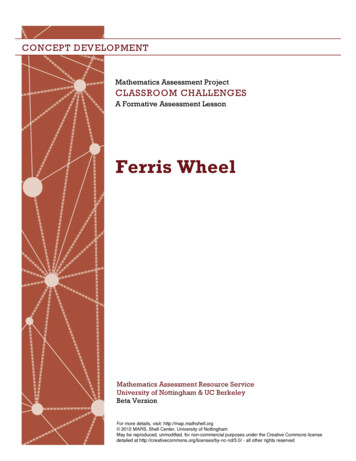
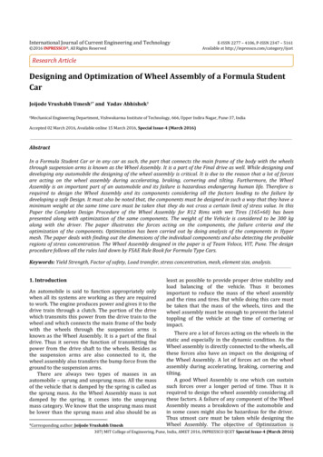
Joijode Vrushabh Umesh et al. Designing and Optimization of Wheel Assembly of a Formula Student Car 251.5 N/mm2y t/2t b 1.7495Where,I t thickness of Wheel PetalWhere,b distance between the hole and the end of petalt thickness of petalIf t 5mm b 0.35 mmb width of petal 27 mm as found from abovecalculationThus the width of the petal is taken to be 5mm.The thickness of the petal is taken as 6mm.Design of Wheel petal due to Side ImpactThe force is obtained from the result (ix) for 1 petal 1962 NThe effective bending Radius 25.25 mmMb 1962 25.25Mb 49540.5 N-mmFig.25 Hub Analysis 1Now,By Flexural Equation,Force acting on Petal as obtained from result (vii) is880 NNow,t 6.61mmThe thickness of petal is taken as 8 mm.3.6.4Analysis and OptimizationFig.26 Hub Analysis 2From the above result it is clear that hub without filletand triangulation support were more prone to failurethan those with fillet and triangulation support.319 MIT College of Engineering, Pune, India, AMET 2016, INPRESSCO IJCET Special Issue-4 (March 2016)
Joijode Vrushabh Umesh et al.Designing and Optimization of Wheel Assembly of a Formula Student CarBesides the stress concentration in the optimizeddesign was less.Table 3 Checking ParametersPartStressInducedEnduranceStrengthFactor onclusionsFollowing conclusions can be drawn from the paper,1) For a component undergoing fatigue loading, thedesign criteria must always be Fatigue orEndurance Strength.2) For carrying out optimization, material should beremoved from the low stress concentration areas.3) In order to minimize stress concentration areas,sharp corners and edges should be avoided.4) If the component is subjected to fatigue failure likeknuckle, then analysis of the components must becarried out in order to obtain actual stressesinduced in the component.5) For accurate results of analysis, mesh quality mustbe high and failing elements must be less than 3%.6) As spindle serves as a component on which theassembly is press fitted, its factor of safety is takenhigh.ReferencesP. Vishwakarma, M. Kanungoo, (2014), Finite ElementAnalysis Of Chervolet Front Hub With The Help OfInventer, International Journal in IT andEngineering, vol.2, Issue 2, ISSN: 2321-1776.G. Fisher,V. V. Graubisic, (1998), Design considerationand durability approval of wheel hub, SAEinternational,11-16-1998.S.dhar, (1988), Fracturer analysis of wheel hubfabricated from pressure die aluminium assembly,Theoretical and applied fracturer mechanics, vol 0902-1988.S.
developing any automobile the designing of the wheel assembly is critical. It is due to the reason that a lot of forces are acting on the wheel assembly during accelerating, braking, cornering and tilting. Furthermore, the Wheel Assembly is an important part of an automobile and its failure is hazardous endangering human life.