Transcription
Drawing and DetailingCDINCLUDED!with SolidWorks 2009Part, Assembly,Drawings, Templates,and moreBy Planchard & Planchard CSWPReferencing the ASME Y14 Engineering Drawing and Related Documentation PracticesSDCPUBLICATIONSSchroff Development Corporationwww.schroff.comBetter Textbooks. Lower Prices
Drawing and Detailing with SolidWorks 2009Drawing Templates and Sheet FormatsProject 2Drawing Templates and Sheet FormatsBelow are the desired outcomes and usage competencies based on the completion ofProject 2.Project Desired Outcomes:Usage Competencies: Ability to apply Document Propertiesto reflect the ASME Y14 EngineeringDrawing and Related DrawingPractices. Understand System Options andDocument Properties which affect thedrawing and Drawing template.Two Drawing Templates:o C-Size Drawing template.o A-Size Drawing template. A C-Size Sheet format. Import an AutoCAD file as a Sheetformat. Insert SolidWorks SystemProperties and Custom Properties. New file location for Drawingtemplates and Sheet format. Ability to create new SolidWorksDocument tabs.PAGE 2-1
Drawing Templates and Sheet FormatsDrawing and Detailing with SolidWorks 2009Notes:PAGE 2-2
Drawing and Detailing with SolidWorks 2009Drawing Templates and Sheet FormatsProject 2-Drawing Templates and Sheet FormatsCreate two Drawing templates. Create a C-size Drawing template and an A-size Drawingtemplate. Create a C-size Sheet format.On the completion of this project, you will be able to: Establish a SolidWorks drawing document session. Distinguish between System Options and Document Properties as they relate todrawings and templates. Create a new SolidWorks File Location for a Drawing template. Set Reference Document Properties in a Drawing template. Create an empty C-size Drawing template. Propagate the settings to the drawingsizes. Import an AutoCAD drawing as a SolidWorks C-size Sheet format. Combine an empty Drawing template and Sheet format to create a C-ANSI-MMDrawing template. Develop Linked Notes to SolidWorks Properties and Custom Properties in the Sheetformat. Insert a company logo in the Title block. Create an A-ANSI-MM Drawing template by combining information from the C-sizeDrawing template and A-size Sheet format.Templates are part, drawing, and assembly documents that include user-definedparameters and are the basis for new documents. You can maintain many differentdocument templates. For example, you can create: A document template using millimeters and another document template using inches. A document template using ANSI and another document template using ISOdimensioning standard. A document template for a Detached drawing.A Detached drawing is design soyou can open and work in drawingfiles without the model files beingloaded into memory or even beingpresent. When opening a Detacheddrawing, SolidWorks checks allsheets in the drawing to be sure thatthey are synchronized with the model.If not, you are warned.PAGE 2-3
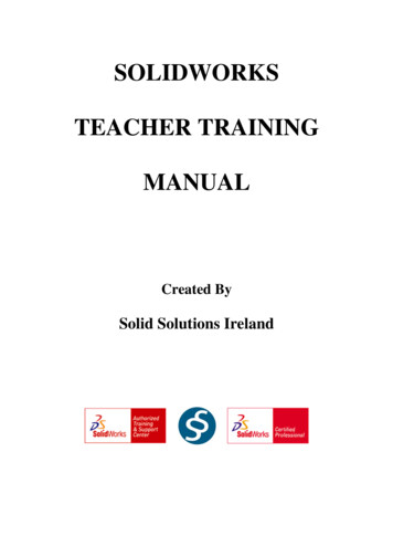
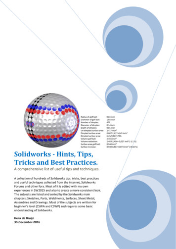
Drawing Templates and Sheet FormatsDrawing and Detailing with SolidWorks 2009Project OverviewYour responsibilities as the designer include developing drawings that adhere to theASME Y14 American National Standard for Engineering Drawing and RelatedDocumentation Practices. The foundation for a SolidWorks drawing is the Drawingtemplate. Drawing size, drawing standards, units and other properties are defined in theDrawing template.Sheet formats contain the following: border, title block, revision block, company name,logo, SolidWorks Properties, and Custom Properties. You are under time constraints tocomplete the project. Conserve drawing time. Create a custom Drawing template andSheet format.Perform the following tasks in this Project: Modify Document Properties and create an empty C-size Drawing template. Import an AutoCAD drawing and save the drawing as a C-size Sheet format. Add System Properties and Custom Properties to the Sheet format. Combine the empty drawing template and imported the Sheet format to create theC-ANSI-MM Drawing template. Generate an empty A-size Drawing template. Modify an existing SolidWorks A-sizeSheet format. Create an A-ANSI-MM Drawing template.Empty FORMAT-C-ACAD.DWGEmpty CDrawingtemplateSheet formatC-FORMAT.SLDDRTSheet mpty ADrawingtemplateC-FORMAT.SLDDRTSheet -FORMAT.SLDDRTPAGE 2-4
Drawing and Detailing with SolidWorks 2009Drawing Templates and Sheet FormatsEngineering Drawing and Related Documentation PracticesDrawing templates in this section are based on the American Society of MechanicalEngineers ASME Y14 American National Standard for Engineering Drawing and RelatedDocumentation Practices.These standards represent the drawing practices used by U.S. industry. The ASME Y14practices supersede the American National Standards Institute ANSI standards.The ASME Y14 Engineering Drawing and Related Documentation Practices arepublished by The American Society of Mechanical Engineers, New York, NY.References to the current ASME Y14 standards are used with permission.ASME Y14 Standard Name:American National Standard EngineeringDrawing and Related Documentation:Revision of the Standard:ASME Y14.100M-1998Engineering Drawing PracticesDOD-STD-100ASME Y14.1-1995Decimal Inch Drawing Sheet Size and FormatANSI Y14.1ASME Y14.1M-1995Metric Drawing Sheet Size and FormatANSI Y14.1MASME Y14.24MTypes and Applications of Engineering DrawingsANSI Y14.24MASME Y14.2M(Reaffirmed 1998)Line Conventions and LetteringANSI Y14.2MASME Y14.3M-1994Multi-view and Sectional View DrawingsANSI Y14.3ASME Y14.41-2003Digital Product Definition Data PracticesN/AASME Y14.5M –1994(Reaffirmed 1999)Dimensioning and TolerancingANSI Y14.5-1982 (R1988)The book presents a portion of the ASME Y14 American National Standard forEngineering Drawing and Related Documentation Practices. Information presented inProjects 2 - 6 represents sample illustrations of drawings, various drawing views, and ordimension types.The ASME Y14 Standards committee develops and maintains additional DrawingStandards. Members of these committees are from Industry, Department of Defense, andAcademia.Companies create their own drawing standards based on one or more of the following: ASME Y14 ISO or other International drawing standards Older ANSI standards Military standardsThere is also the “We’ve always done it this way” drawing standard or “Go ask theDrafting supervisor” drawing standard.PAGE 2-5
Drawing Templates and Sheet FormatsDrawing and Detailing with SolidWorks 2009File ManagementFile management organizes parts, assemblies, and drawings. Utilize file management toorganize drawing templates and sheet formats.Why do you require file management? Answer: Organize documents. A top levelassembly necessitates hundreds or even thousands of drawings to document its parts andsub-assemblies. Drawings utilize various drawing templates and sheet formats.Parts, assemblies, and drawings are distributed between team members to conservedevelopment time. Design changes occur frequently in the development process. Howdo you manage and control changes? Answer: Through file management. Filemanagement is a very important tool in the development process. Utilize file folders toorganize projects, vendor components, templates, and libraries.The files and folders required to complete the projects in this book are located on theenclosed CD.Activity: File ManagementCreate a new folder in Windows to down load files.1)Click Start from the Windows Taskbar.2)Click My Documents in Windows.3)Click File, New, Folder from the Main menu.Enter the new folder name.4)Enter DRAWING-W-SOLIDWORKS-2009.Select the Microsoft Windows commands eitherfrom the Main menu, toolbar icons or with the rightmouse button. Windows XP is used in this section.Return to the DRAWING-W-SOLIDWORKS-2009 folder.5)Click the DRAWING-W-SOLIDWORKS-2009 folder.Copy the files from the enclosed CD in the book to the newfolder.6)Insert the enclosed CD.7)Select your CD drive.8)Right-click Explore. View the available files andfolders.9)Copy the files and folders to the DRAWING-WSOLIDWORKS-2009 folder. The DRAWING-WSOLIDWORKS-2009 folder is the working folder for thisbook.PAGE 2-6
Drawing and Detailing with SolidWorks 2009Drawing Templates and Sheet FormatsStore project Drawing templates in theMY-TEMPLATES file folder. StoreProject Sheet formats in the MYSHEETFORMATS folder.The Drawing templates and Sheetformats which are created in thisproject, are located in the downloaded PROJECT2TEMPLATES-SHEETFORMTS folder.Default Drawing Template, Sheet Format, andSheet SizeThe foundation of a SolidWorks drawing is the Drawingtemplate. Drawing sheet size, drawing standards, companyinformation, manufacturing and or assembly requirements;units, layers, line styles and other properties are defined inthe Drawing template.A Sheet format is incorporated into the Drawing template.The Sheet format contains the following items: Sheet border Title block Revision block information Company name and or logo information Custom Properties SolidWorks PropertiesPAGE 2-7
Drawing Templates and Sheet FormatsDrawing and Detailing with SolidWorks 2009SolidWorks starts with a default Drawingtemplate, drawing.drwdot.The default Drawing template is locatedin the C:\Documents and Settings\AllUsers\Application Data\SolidWorks\SolidWorks2009\templates folder on a non-network system. SolidWorksis the name of the installation folder.New SolidWorks DocumentThe Templates folder corresponds to the Templates tabdisplayed in the New SolidWorks Document dialog box.The Large Icons option displays the full name, and a largedocument icon.The List option displays the document icons in a list format.The List Details option displays the document name, size and last modified date.PAGE 2-8
Drawing and Detailing with SolidWorks 2009Drawing Templates and Sheet FormatsSheet Format/SizeThe Sheet Format/Size dialog box defines the Sheet format and the paper size. The U.S.default Standard Sheet Format is A-Landscape.slddrt. The Display sheet format boxtoggles the Sheet format display on/off.The Standard Sheet formats are located in the C:\Program Files\SolidWorks 2009 ona non-network system.PAGE 2-9
Drawing Templates and Sheet FormatsDrawing and Detailing with SolidWorks 2009ASME Y14.1 Drawing Sheet Size and FormatThere are two ASME standards that define sheetsize and format. They are:1.ASME Y14.1-1995 Decimal Inch DrawingSheet Size and Format2.ASME Y14.1M-1995 Metric Drawing SheetSizeA-Landscape (Default)11in x 8.5inDrawing size refers to the physical paper size usedto create the drawing. The most common papersize in the U.S. is the A-size: (8.5in. x 11in.).The most common paper size internationally is theA4 size: (210mm x 297mm). The ASME Y14.11995 and ASME Y14.1M-1995 standards containboth a horizontal and vertical format for A and A4size respectively. The corresponding SolidWorksSheet format is Landscape for horizontal andPortrait for vertical.SolidWorks predefines U.S. drawing sizes Athrough E. Drawing sizes: F, G, H, J, & K utilizethe Custom sheet size option. Enter values forwidth and height. SolidWorks predefines metricdrawing sizes A4 through A0. Metric roll papersizes utilize the Custom sheet size option.The ASME Y14.1-1995 Decimal Inch Drawing andASME Y14.1M-1995 Metric Sheet size standard are as follows:Drawing Size:Size in inches:Drawing Size:Size in Millimeters:“Physical Paper”VerticalHorizontal“Physical Paper”MetricVerticalHorizontalA horizontal (landscape)8.511.0A08411189A vertical 0A3297420D22.034.0210297E34.044.0A4 horizontal(landscape)F28.040.0A4 vertical (portrait)297210G, H, J and K apply to rollsizes, User DefinedUse caution when sending electronic drawings between U.S. and Internationalcolleagues. Drawing paper sizes will vary. Example: An A-size (11in. x 8.5in.) drawing(280mm x 216mm) does not fit a A4 metric drawing (297mm x 210mm). Use a largerpaper size or scale the drawing using the printer setup options.PAGE 2-10
Drawing and Detailing with SolidWorks 2009Drawing Templates and Sheet FormatsStart a new session of SolidWorks. Create a new drawing with the default Drawingtemplate. Utilize C-size paper with no Sheet formatdisplayed.The sheet border defines the C-size drawing: 22in. x 17in,(558.80mm x 431.80mm). A new Graphics windowdisplays the C-Landscape Drawing, named Draw1.Landscape indicates that the larger dimension is along thehorizontal. A-Portrait and A4-Portrait indicate that thelarger dimension is along the vertical.Activity: Default Drawing TemplateStart a SolidWorks session.10) Click Start, All Programs from the Windows Main menu.11)Click the SolidWorks 2009 folder.12)Click the SolidWorks 2009 application. The SolidWorksGraphics window is displayed.Pin the Menu bar toolbar and the Menu bar menu.Select the default Drawing template.13)Click New14)Double-click Drawing from the Templates tab.from the Menu bar toolbar.Create a C-Landscape sheet.Click C-Landscape from the Standard sheet size drop-downmenu.15)16)Uncheck the Display sheet format box.17) Click OK from the Sheet Format/Size dialog box.Exit the Model View PropertyManager.18)Click Cancelfrom the Model View PropertyManager. TheFeatureManager is displayed with Draw1 as the defaultdrawing name.The Model View PropertyManager is displayed if theStart command when creating new drawing box is checked.Save Draw1.19) Click Save As from the Consolidated Menu bartoolbar.20)Select the DRAWING-W-SOLIDWORKS-2009 folder.21)Click Save. The Draw1 FeatureManager is displayed.PAGE 2-11LandscapePortrait
Drawing Templates and Sheet FormatsDrawing and Detailing with SolidWorks 2009Activity: Display the Line Format ToolbarReview the CommandManager options and displaythe Line Format toolbar.22) Right-click in the grey area of theCommandManager as illustrated.23)Click Customize. The Customizedialog box is displayed. The Toolbarstab is displayed by default.24)Check the Line Format box. The LineFormat toolbar is displayed. Explore thetabs and your options to customizeyour options.25)Click and drag the Line Formattoolbar off the Graphics window.Close the Customize dialog box.26) Click OK.By default, the Show tooltips optionis selected. Apply the Customize dialogbox to set short cut keys from thekeyboard.Line Format ToolbarThe Line Format toolbar controls the following options: LayerProperties, Line Colorand Color Display Mode, Line Thickness, Line Style,.Utilize the Line Format toolbar when creating a Drawing template.Select the tools and menu options that are displayed in bold icons and black text.The tools and menu options that are displayed in gray are called grayed-out. The grayicon or text cannot be selected. Additional information is required for these options.PAGE 2-12
Drawing and Detailing with SolidWorks 2009Drawing Templates and Sheet FormatsActivity: Create a Keyboard ShortcutCustomize the Keyboard.27) Click Tools, Customize from theMenu bar menu. The Customizedialog box is displayed.Note: There are numerous ways toaccess commands and menus inSolidWorks.28)Click the Keyboard tab.29)Select View for Categories.30)Select Planes for Commands.31)Click a position inside the Shortcut(s)box.32)Enter P for new shortcut key. Note:Shift P is displayed in the Shortcut(s)box.33)Click OK from the Customize dialogbox.34)Save the drawing. Draw1 is thedefault name.The short cut key P is displayednext to the Planes option in the Viewmenu. Create additional short cut keysas an exercise.PAGE 2-13
Drawing Templates and Sheet FormatsDrawing and Detailing with SolidWorks 2009Cursor FeedbackSolidWorks provides system feedback by attachinga symbol to the mouse pointer cursor. The systemfeedback symbol indicates what you are selecting orFaceEdge Dimension Vertexwhat the system is expecting you to select. As youmove the mouse pointer across your model, systemfeedback is provided to you in the form of symbols, riding next to thecursor. The cursor has an important role in the SolidWorks UserInterface.The mouse pointer provides feedback in both the Drawing Sheetmodes. The mouse pointer displays theand Drawing ViewDrawing Sheetexecuted.icon when the Sheet properties and commands areThe mouse pointer displays the Drawing ViewView properties and commands are executed.icon when theView the mouse pointer for feedback to select Sheet, View,Component and Edge properties in the Drawing.Sheet Properties display properties of the selected sheet. Rightclick in the sheet boundary.View Properties display properties of theselected view. Right-click on the viewboundary.Sheet PropertiesSheet Properties display properties of the selected sheet. SheetProperties define the following: Name of the Sheet, Sheet Scale,Type of Projection (First angle or Third angle), Sheet Format,Sheet Size, View label, and Datum label.PAGE 2-14
Drawing and Detailing with SolidWorks 2009Drawing Templates and Sheet FormatsThe Sheet format and Sheet size are set in the default Drawing template. Review theSheet Properties. The Standard sheet size option is grayed out.The Sheet format file extension is .drt. The Sheet format option is grayed out. The Csize paper, width, and height dimensions are listed under the Custom sheet size option.Activity: Sheet PropertiesDisplay the Sheet Properties.35) Right-click inside the Sheetboundary.36)Click Properties. The SheetProperties dialog box isdisplayed. Name of the sheetis Sheet1. Scale is 1:1. Typeof projection: Third angle.First or Third angleprojection was set at the initialinstallation of the SW software.Exit the Sheet Properties dialog box.37) Click OK from the SheetProperties dialog box.The Sheet name is Sheet1. TheFeatureManager and Sheet tabdisplay the Sheet name. TheSheet Scale is 1:1. The Previewbox contains no Sheet format.Custom sheet size is 22in x 17in(558.80mm x 431.80mm).Third Angle projection isprimarily used in the United States. Third Angle projection is used in this book.System OptionsSystem Options are stored in the registry of the computer.System Options are not part of the document. Changes tothe System Options affect all current and future documents.There are hundreds of Systems Options. Review a few of theoptions in this section.Click the Options tool to activate the System Options dialog.PAGE 2-15
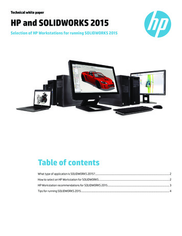
Drawing Templates and Sheet FormatsDrawing and Detailing with SolidWorks 2009Display Styles / modesDisplay modes for a Drawing view are similar to a part exceptwith the addition of the 3D Drawing view tool. This tool providesthe ability to rotate the model in an existing view.Wireframe and Shaded Display modes provide thebest Graphic performance. Mechanical detailsrequire Hidden Lines Visible display and HiddenLines Removed display. Select Shaded/HiddenLines Removed to display Auxiliary Views toavoid confusion.Tangent Edges Visible provides clarity for thestart of a Fillet edge. Tangent Edges Removedprovides the best graphic performance.Right-click in the view boundary to access the Tangent Edge options.Utilize the Lightweight Drawing option to improve performance for largeassemblies.WireframeHidden Lines VisibleHidden Lines RemovedTangent Edges Visible Tangent Edges With FontPAGE 2-16ShadedTangent Edges Removed
Drawing and Detailing with SolidWorks 2009Drawing Templates and Sheet FormatsActivity: System Options-Display StyleSet the default display style.38) Click Optionsfrom the Menu bar toolbar.The System Options - General dialog box isdisplayed.39)Click Display Style from the System Optionstab.40)Check the Hidden lines removed box for theDisplay style for new views.41)Check the Visible box for the default Tangentedges in the new views. Note: High quality isthe default option for display quality.File LocationsSystem Options, File Locations, Document Templates option determines the path tolocate a Custom Drawing template. Add the MY-TEMPLATES folder to the FileLocations. The folder listed in the Document Templates option determines the tabsdisplayed in the New SolidWorks Document dialog box.Activity: System Options-File LocationsSet file locations for drawing templates.42) Click File Locations fromthe System Options tab.43)Select DocumentTemplates from the Showfolders for drop-downmenu.44)Click the Add button.45)Click Browse.46)Select the DRAWING-WSOLIDWORKS-2009\MYTEMPLATES folder.47)Click OK from the Browse For Folder box.48)Click Yes.49)Click OK from the System Options dialog box.50)Click Yes.PAGE 2-17
Drawing Templates and Sheet FormatsDrawing and Detailing with SolidWorks 2009Save Draw1.51) Save Draw1.The MY-TEMPLATES tab is displayed in the NewSolidWorks Drawing dialog box. The MY-TEMPLATES tab isnot displayed if the folder is empty. The System Option, FileLocations list determines the order of the tabs. Save theDrawing Templates to the MY-TEMPLATES folder.Document PropertiesDocument Properties apply to the current document. Set thefollowing: Drafting Standard, Grid/Snap, Units, Line Fonts,and Image Quality in Document Properties.When the current document is saved as a template, the currentparameters are stored with the template. New documents thatutilize the same template contain the stored parameters.Conserve drawing time. Set the Document Properties in theDrawing template. Document Properties options containhundreds of parameters. Examples are addressed in thissection. Explore other parameters through SolidWorks HelpTopics.There are numerous text styles and sizes available inSolidWorks. Companies develop drawing format standardsand use specific text height for Metric and English drawings.The ASME Y14.2M-1992(R1998) standard lists the following:lettering, arrowhead, line conventions and letteringconventions for engineeringdrawings and relateddocumentation practices.FontCentury Gothic is the defaultSolidWorks font.Create an assessment page totest that your Printer/Plotterdrivers support the defaultSolidWorks font.PAGE 2-18
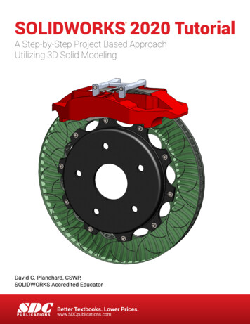
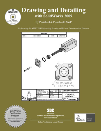
Drawing and Detailing with SolidWorks 2009Drawing Templates and Sheet FormatsMinimum Drawing Letter Height based on ASME Y14.2.AnnotationInch drawing sizes: A, B, CMetric drawing sizes: A2, A3, A4Inch drawing sizes: D, EMetric drawing sizes: A0, A1InchMillimeterInchMillimeterDrawing Title, Drawing Size,Cage Code, Drawing Numberand Revision letter positionedinside the Title block.12in3mm.24in6mmSection views, Zone letter andnumerals.24in6mm.24in6mmDrawing block headings in Titleblock.10in2.5mm.10mm2.5mmAll other characters inside theSheet boundary. Correspondsto the SW Dimension and Notefont.12in.3mm.12in3mm.ArrowheadsControl arrowheads through the Drafting Standard,Dimensions option in an active drawing document. Utilize asolid filled arrowhead with a 3:1 ratio. The arrowhead widthis proportionate to the line thickness. The Dimension linethickness is 0.3mm.The Dimension arrow is based on theDimension line. SolidWorks definesarrow size with three options:o Heighto Widtho LengthHeight corresponds to the arrow width.Width corresponds to the arrow taillength. Length corresponds to thedistance from the tip of the arrow to theend of the tail.The Section line thickness, (Drafting Standard, ViewLabels, Section) is 0.6mm. The Section arrow is basedon the Section line. The Section arrow length is 6mm.The Section arrow width is 2mm.The illustration displays the default mm values.PAGE 2-19
Drawing Templates and Sheet FormatsDrawing and Detailing with SolidWorks 2009Line WidthsThe ASME Y14.2M-1992 (R1998) standard recommends two line widths with a 2:1ratio. The minimum width of a thin line is 0.3mm. The minimum width of a thick,“normal” line is 0.6mm.A single width line is acceptable on CAD drawings. Two line widths are used inthis Project: Thin: 0.3mm and Normal: 0.6mm.Apply Line Styles in the Line Font Document Properties. Line Font determines theappearance of a line in the Graphics window. SolidWorks styles utilized in this Projectare as follows:SolidWorks Line StyleThin: ck ChainVarious printers/plotters providevariable Line Weight settings. Example:Thin (0.3mm), Normal (0.6mm), andThick (0.6mm).Refer to the printer/plotter owner’smanual for Line weight setting. Utilizethe Document Property, Line Styleoption to create, save, load, and deleteline styles.PAGE 2-20Normal: (0.6mm)
Drawing and Detailing with SolidWorks 2009Drawing Templates and Sheet FormatsScale large drawing sheets with theResolution and Scale option located in theFile, Page Setup Menu bar menu. Use theScale to fit option to resize the drawingsheet to the physical paper size.Use Scale to resize the drawing sheet by apercentage to the physical paper size.Line FontThe ASME Y14.2M-1992(R1998)standard addresses the type and style oflines used in engineering drawings.Combine different Line Styles and usedrawing layers to achieve the followingtypes of ASME lines:ASME Y14.2-1992(R1998) TYPE ofLINE & example:SolidWorks LineFont Type of Edge:Style:Thickness:Visible line displays the visible edges orcontours of a part.Visible EdgeSolidThick “Normal”Hidden line displays the hidden edges orcontours of a part.Hidden EdgeDashedThinSection lining displays the cut surface of apart assembly in a section view.CrosshatchSolidCenter line displays the axes of centerplanes of symmetrical parts/features.Construction CurvesCenterThinSketch Thin Center Lineand Thick Visible lines ondrawing layer.Symmetry line displays an axis ofsymmetry for a partial view.Dimension lines/Extension lines/Leaderlines combine to dimension drawings.ThinDifferent Hatch patternsrelate to differentmaterialsDimensionsSolidThinSection LinePhantomThickView ArrowsSolidThick, “Normal”Extension LineLeader LineCutting plane line or Viewing plane linedisplay the location of a cutting plane forsectional views and the viewing position forremoved views.PAGE 2-21
Drawing Templates and Sheet FormatsDrawing and Detailing with SolidWorks 2009Break line displays an incomplete view.Broken viewShort BreaksUse Curved for ShortBreaksLong BreaksUse Small Zig Zag forLong BreaksPhantom line displays alternative positionof moving parts.Sketch Thin PhantomLine on drawing layerStitch line displays a sewing or stitchingprocess.Sketch Thin Stitch Lineon drawing layerChain line displays a surface that requiresmore consideration or the location of aprojected tolerance zone.Sketch Thick Chain Lineon drawing layerThe following default lines are defined inSolidWorks: Solid, Dashed, Phantom, Chain,Center, Stitch, Thin/Thick Chain.Define these line types on a separate drawinglayer.Document Properties-DimensionsControl the Dimensions options through DocumentProperties. The Drafting Standard, Dimensionsdetermines the display on the drawing. Millimeterdimensioning and decimal inch dimensioning arethe two key types of units specified on engineeringdrawings.There are other dimension types specified forcommercial commodities such as pipe sizes andlumber sizes. Develop separate Drawing templatesfor decimal inch units.PAGE 2-22
Drawing and Detailing with SolidWorks 2009Drawing Templates and Sheet FormatsASME Y14.2-1992(R1998) and the ASME Y14.2M Line Conventions and Letteringstandard define text height, arrows and line styles for inch and metric values. Review theDetailing Document Properties options function before entering their values.Drafting (Dimensioning) StandardThe Drafting standard options are: ANSI: American National StandardsInstitute ISO: International StandardsOrganization DIN: Deutsche Institute für Normumg (German) JIS: Japanese Industry Standard BSI: British Standards Institution GOST: Gosndarstuennye State Standard(Russian) GB: Guo Biao (Chinese)Dual dimensions Display OptionThe Dual dimensions display check box showsdimensions in two types of units on the drawing.Select Dual dimensions display. Select the On topoption. Select Dual Dimension Length units. Theprimary units display is 100mm. The secondaryunits display is [3.94]in.Fixed Size Weld Symbols OptionThe Fixed size weld symbols checkbox displays thesize of the weld symbol. Scale the symbols accordingto the dimension font size.PAGE 2-23
Drawing Templates and Sheet FormatsDrawing and Detailing with SolidWorks 2009Display Datums per 1982 OptionThe Display datums per 1982 checkbox displays the ANSIY14.5M-1982 datums. Use the ASME Y14.5M-1994(R1999)datums in this text.Leading Zeroes and Trailing Zeroes OptionThe Leading zeroes list box contains three options: Standard: Active by default. Zeros are displayed based on thedimensioning standard. Show: Zeros before decimal points are displayed. Remove: Zeros are not displayed.The Trailing zeroes list box contains four options: Smart: Active by default. Trailing zeros are trimmed forwhole metric values. (Conforms to ANSI and ISOstandards.) Show: Dimensions have trailing zeros up to thenumber of decimal places specified in Tools, Options,Document Properties, Units section. Remove: All trailing zeros are removed. Standard: Trims trailing zeroes to the ASMEY14.5M-1994 standard.Alternative Section Display OptionThe ASME Y14.2M-1992(R1998) standard supports twodisplay styles. The default section line displays acontinuous Phantom line type (D-D).Check the Alternate section display checkbox toallow for a gap in the section line (B-B).Centerline Extension and Center Marks OptionThe Centerline extension value controlsthe extension length beyond the sectiongeometry.Center marks specify the default centermark size used with arcs and circles.Center marks are displayed with orwithout Center mark lines.3mmPAGE 2-243mm
Drawing and Detailing with SolidWorks 2009Drawing Templates and Sheet FormatsThe Center mark lines extend pass the circumferenceof the selected circle. Select the Center mark sizebased on the drawing size and scale.Auto Insert on View Creation OptionAuto insert on view creation locates Center marks onthe appropriate entities when a new view is insertedinto a drawing. By default Ce
ASME Y14.1M-1995 Metric Drawing Sheet Size and Format ANSI Y14.1M ASME Y14.24M Types and Applications of Engineering Drawings ANSI Y14.24M ASME Y14.2M(Reaffirmed 1998) Line Conventions and Lettering ANSI Y14.2M ASME Y14.3M-1994 Multi-view and Sectional View Drawings ANSI Y14.3 ASME Y14.41-2003 Digital Product Definition Data Practices N/A ASME .