Transcription
HOLLOWSTRUCTURALSECTIONSBeam Load TablesOF NORTH AMERICA1 9 9 8R E V I S E DE D I T I O N
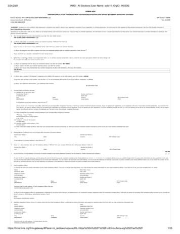
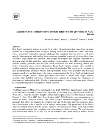
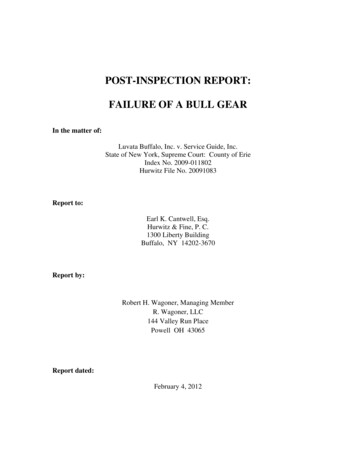
HSS Manufacturing MethodsThe transformation of steel strip into hollow structural sections (HSS) is the result of operations including forming, welding and sizing.Currently three methods are being used in North America for the manufacture of HSS. These methods, including two ERW methods and anSAW method, are described below. Both ERW methods meet ASTM A 500 and CSA G-40.21 requirements for the manufacture of HSS, and theERW sizes included in this publication may be produced to either standard. The SAW method is not included as a manufacturing process inthe ASTM or CSA specification. SAW sizes listed in this publication can be specified to meet desired physical and dimensional criteria of ASTMA500 and CSA G-40.215 6 7Electric Resistance Welding (ERW) ProcessIn the tube mill, flat steel strip (1) is formed continuously around itslongitudinal axis to produce a round tube. This is done by moving thestrip through a progressive set of rolls (2-6). The strip edges (7) areheated by either high frequency induction or contact welding and thenforged together by weld rolls to create a continuous longitudinal weldwithout the addition of filler metal. The weld seam (8) is then cooledand processed through a set of sizing/shaping rolls which cold-form itinto a round (9), square (10) or rectangular (11) section.432189Form-Square Weld-Square (ERW) ProcessIn the weld mill, driven forming dies progressively shape the flat strip(1) by forming the top two corners (2) of the square or rectangular tubein the initial forming station. Subsequent stations form the bottom twocorners (3) of the shape. No cold working of the sides of the shape isperformed, and the shape’s seam is welded by high-frequency contactswhen the tube is near its final shape and size. The welded tube (4) iscooled and then driven through a series of sizing stations which qualifiesthe tube’s final dimensions.1041233Submerged Arc Weld (SAW) ProcessTwo identical pieces of flat strip (1) are placed in a press brake andformed into two identical halves (2) of a finished tube size. A backup baris tack welded to each leg of one of the half-sections (3). The two halfsections are fitted together toe-to-toe (4) and welded by the submergedarc process to complete the square or rectangular section (5).251211234211
ForewordTables of allowable uniformly distributed loads are presented for rectangular and square hollow structural sections (HSS) manufactured by the electric resistance welding (ERW) and the submerged arc welding(SAW) processes. Tables of maximum unbraced compression flange lengths and tables of midspan deflections for uniformly loaded simple span beams are also included.The tables of allowable uniformly distributed loads have been calculated in accordance with the 1989“Specification for Structural Steel Buildings - Allowable Stress Design and Plastic Design” published by theAmerican Institute of Steel Construction. The allowable uniformly distributed loads are based upon sectionproperty data for HSS that were recalculated in 1996 to account for today’s more precise manufacturingmethods. The recalculated section property data for HSS are published in “Hollow Structural Sections Dimensions and Section Properties” available from the Steel Tube Institute of North America.Tables are presented for two specified minimum yield stress steels - Fy 46 ksi and Fy 50 ksi.Allowable uniform loads for HSS sizes produced by the ERW and SAW manufacturing methods are presented in separate tables.The allowable uniformly distributed loads are based upon the allowable bending stress, Fb, equal to0.66Fy and 0.60Fy. The allowable uniformly distributed loads for slender sections are calculated in accordance with AISC “Specification” Appendix B. Slender sections are indicated in the tables with an asterisk(*) immediately following the design wall thickness parameter and a double asterisk (**) immediatelyfollowing the modified value of Sx.The tabulated loads include the weight of the HSS beam which must be deducted to determine the netload that the beam will support. It is assumed that the load is applied in the plane of the minor axis and thatthe HSS beam deflects vertically in the plane of bending only.Deflections corresponding to the tabulated loads are also given. Deflections caused by actual loadingless than the full allowable load may be obtained by multiplying the tabulated deflection by the ratio of theactual load to the tabulated allowable uniform load.Tabulated values of maximum laterally unsupported lengths, Lc, of compression flanges of HSS beamsfrom 1 1/4 inches through 32 inches in width and for varying ratios of M1/M2 are presented for Fy 46 ksiand Fy 50 ksi specified minimum yield stress steels - see page xx and page xx. The Lc values are calculated in accordance with AISC “Specification” Sections B5 and F3 which specify that the laterally unsupportedlength of the compression flange of an HSS beam for which the allowable bending stress may be taken at0.66Fy shall not exceed the value(1950 1200except that it need not be less than 1200(b/Fy).)M1M2bFyRefer to Part 2, Beam and Girder Design, in the AISC 9th edition “Manual of Steel Construction” for adiscussion of lateral support of beams, beams with concentrated loads and vertical deflection. Symbols usedin these tables follow those used in the AISC “Manual”Tables of deflections for fully stressed, uniformly loaded simple beams from 1 1/4 inches through 32inches in depth and for varying span lengths are also included. These tables are presented for allowablebending stresses equal to 33 ksi (0.66 x 50 ksi), 30.0 ksi (0.60 x 50 ksi) and 27.6 ksi (0.60 x 46 ksi) - seepages xx - yy. Deflections for allowable bending stress equal to 30.36 ksi (0.60 x 46 ksi) can be obtained byadding approximately 1 % to the deflection values presented in the table for allowable bending stress equalto 30.0 ksi.4
Table of ContentsPageHow to Use the Beam Load Tables 6Lc Tables 7Beam Load TablesRectangular HSS (ERW)Square HSS (ERW)Fy 46 ksi 8Fy 46 ksi 38Rectangular HSS (ERW)Square HSS (ERW)Fy 50 ksi 50Fy 50 ksi 80Rectangular HSS (SAW)Square HSS (SAW)Fy 46 ksi 92Fy 46 ksi 98Rectangular HSS (SAW)Square HSS (SAW)Fy 50 ksi 102Fy 50 ksi 108Deflection Tables 113The information presented in this publication has been prepared in accordance with recognized engineeringprinciples and is for general information only.While it is believed to be accurate, this information should notbe used or relied upon for any specific application without competent professional examination andverification of its accuracy, suitability, and applicability by a licensed professional engineer, designer, orarchitect.The publication of the material contained herein is not intended as a representationor warranty on the part of The Steel Tube Institute of North America or of any other personnamed herein, that this information is suitable for any general or particular use or offreedom from infringement of any patent or patents. Anyone making use of thisinformation assumes all liability arising from such use.Caution must be exercised when relying upon other specificationsand codes developed by other bodies and incorporated by referenceherein since such material may be modified or amended from timeto time subsequent to the printing of this edition.The Institute bearsno responsibility for such material other than to refer to it andincorporate it by reference at the time of the initial publicationof this edition.
How To Use The Beam Load TablesExample IExample IIIA simply supported 8 in. x 4 in. x 1/4 in. ERW HSS beam ofFy 46 ksi (ASTM A500 Gr. B) spans 16 feet. The compressionflange is braced laterally at 3 feet from each end. Determine the totaluniform load capacity and midspan deflection for loading in theplane of the minor axis.Select the lightest 7-inch deep, simply supported ERW HSS beam ofFy 50 ksi (ASTM A500 Gr. C) to span 6 feet and support a load of5.3 kips per foot (includes estimated weight of HSS beam). Thebeam is laterally supported for its entire length.Required total uniform load to be supported is equal to 31.8 kips (5.3 kips/ft. x 6 ft.)Due to symmetry, M1/M2 – 1.0 for the 10 ft. center segmentof the HSS beam. Enter the Fy 46 ksi Table of Lc values forM1/M2 – 1.0 and a flange width equal to 4 inches, and note thatLc 8.7 ft. 10.0 ft.; therefore Fb 0.60 Fy 27.6 ksi. Enter theFy 46 ksi Load Table for the 8 in. x 4 in. x 1/4 in. HSS. Readacross the row at the span equal to 16 feet and note that the totalallowable uniform load is 12 kips ( in the shaded area) with acorresponding midspan deflection equal to 0.91 in.Enter the Fy 50 ksi Load Table for the 7-inch deep HSS. Read across the rows atthe span equal to 6 ft. and note the following:7 in. x 5 in. x 1/4 in. HSS (19.02 lbs./ft.) can support 37 kips 31.8 kips - O.K.7 in. x 5 in. x 3/16 in. HSS (14.53 lbs./ft.) can support 29 kips 31.8 kips - No Good7 in. x 4 in. x 1/4 in. HSS (17.32 lbs./ft.) can support 32 kips 31.8 kips - O.K.7 in. x 4 in. x 3/16 in. HSS (13.25 lbs./ft.) can support 25 kips 31.8 kips - No GoodExample II7 in. x 3 in. x 3/8 in. HSS (22.37 lbs./ft.) can support 36 kips 31.8 kips - O.K.7 in. x 3 in. x 5/16 in. HSS (19.08 lbs./ft.) can support 31 kips 31.8 kips - No GoodA simply supported 10 in. x 6 in. x 1/4 in. ERW HSS beam ofFy 50 ksi (ASTM A500 Gr. C) spans 18 feet. The compressionflange is braced laterally at the ends. Determine the total uniformload capacity and midspan deflection for loading in the plane of theminor axis.Select: 7 in. x 4 in. x 1/4 in. HSS (weight 17.32 lbs./ft.)Example IVDue to symmetry, M1/M2 0 for the simply supported HSS beam.Enter the Fy 50 ksi Table of Lc values for M1/M2 0 and aflange width equal to 6 inches, and note that Lc 19.5 ft. 16.0 ft.;therefore Fb 0.66Fy 33.0 ksi. Enter the Fy 50 ksi Load Tablefor the 10 in. x 6 in. x 1/4 in. HSS. Read across the row at the spanequal to 18 feet and note that the total allowable uniform load is24 kips ( in the unshaded area) with a corresponding midspandeflection equal to 1.11 in.A simply supported 10 in. x 6 in. x 1/4 in. ERW HSS beam ofFy 50 ksi (ASTM A500 Gr. C) spans 18 feet and supports auniformly distributed load of 500 pounds /ft. (Total DL LL). Thecompression flange is braced laterally at the ends. Determine themidspan deflection for the applied loading.Total load supported 500 pounds/ft. x 18 ft. 9. kipsTotal allowable uniform load equals 24 kips; corresponding midspandeflection equals 1.11 in. (see Example II).Deflection due to applied loading: 1.11 in. x9 kips24 kips 0.42 in.Beam Load Tables6
HSS Beam Load Tables/Structural Steel TubingLcMaximum unbraced length of compression flange, in feet, for which allowable bending stress, Fb, may be taken at 0.66 Fy.Fy 46 ksiFlange Width, InchesM1M2 1 1/4 1 1/21 5/8 1 3/422 1/4 2 1/233 1/244 1/255 1/2678910121416 .434.239.945.751.457.168.579.991.31820222426283032 232.938.443.949.454.965.976.887.898.8 031.636.942.247.452.763.373.884.394.9 830.335.440.445.550.560.770.880.991.0 29.033.938.743.548.458.067.777.487.196.7 27.732.337.041.646.255.464.773.983.292.4 6.430.835.239.644.052.861.670.479.288.096.8 5.129.333.537.741.850.258.667.075.383.792.1 .827.831.735.739.747.655.563.571.479.387.395.2 98.9– 2.899.5– 6.792.999.1– 0.786.492.2– .679.985.2– 573.478.3– .560.965.269.620222426283032– 0.625to– 1.0Fy 50 ksiFlange Width, InchesM1M2 1 1/4 1 1/21 5/8 1 3/422 1/4 2 1/233 1/244 1/255 1/267891012141618 931.536.842.047.352.563.073.584.094.5 830.335.440.445.550.560.670.780.890.9 29.134.038.843.648.558.267.977.687.397.0 27.932.637.241.946.555.865.174.483.793.0 26.731.235.640.144.553.462.371.280.189.097.9 5.529.834.038.342.551.059.568.076.585.093.5 4.328.432.436.540.548.656.764.872.981.089.197.2 .127.030.834.638.546.253.961.669.377.084.792.4 0.24.65.55.96.47.38.29.111.012.814.616.41
Refer to Part 2, Beam and Girder Design, in the AISC 9th edition “Manual of Steel Construction” for a discussion of lateral support of beams, beams with concentrated loads and vertical deflection. Symbols used in these tables follow those used in the AISC “Manual” Tables of deflections for fully stressed, uniformly loaded simple beams from 1 1/4 inches through 32 inches in depth and .