Transcription
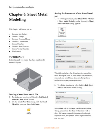
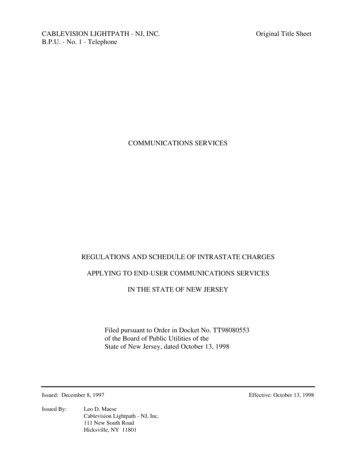
TECHNICAL DATA SHEET19ISSUED BY TIMBER QUEENSLANDPERGOLAS ANDCARPORTSRECOMMENDED PRACTICE // MARCH 2014This data sheet contains Timber Queensland’s recommendations for attached and detached timber pergolasand carports with relatively flat skillion roofs and lightweight roofing (max 10 kg/m2). It covers the mostcommon timber species, sizes and fixing methods. Where appropriate, separate tables are provided for lowBattens C3 iswind speed areas (N1, N2, N3 and C1) and higher wind speed area (N4 and C2). Wind classificationbeyond the scope of this data sheet. For alternative stress grades, fixing methods, larger spans, pitchedroofs, wind classification C3 etc., refer AS 1684 – Residential timber-framed construction.Note: The sizes and fixings assume pergolas are either roofed (lightweightroofing 10 kg/m3), or could have a roof installed at some future stage.Battens(a) Typical attached pergolaTIMBER SELECTIONPergola and carport framing exposed to the weather, includingposts fixed above ground, shall be either preservative treated pine,durability class 1 or 2 hardwood, or cypress.Posts embedded in the ground shall be in-ground durability class 1hardwood, preservative treated pine or cypress (sapwood free).Hardwood posts and framing containing sapwood shall bepreservative treated.Preservative treatment for posts in the ground shall be H5. Exposedframing and posts above ground shall be treated to H3.Note: Lower durability timbers (e.g. Oregon, Tasmanian Oak, Victorian Ash) arenot recommended for pergolas unless fully protected by a roof.LedgerKnee BraceRafterBeamEnds of rafters andbeams shaped toLedgerreduce end grainexposureRafterPostKnee BraceFootingBeamEndsrafters andHotofdippedbeamsshapedstirruptogalvanisedreduce end grainexposurePostFootingHot dippedgalvanised stirrupMEMBER SIZESTables 1, 2, 5 and 10 list the recommended sizes and spans for themost commonly available timber species. For alternative speciesand larger spans refer AS 1684.(b) Typical freestanding carportNote: When appropriate separate tables are provided for different windclassifications. Tables with a suffix L are for low wind speed areas (N1, N2, N3and C1). Tables with a suffix H are for higher wind speed areas (N4 and C2).Lightweight roofing(max. 10kg/m2)FIXINGSLightweight roofing(max. 10kg/m2)Fixings (stirrups, brackets, bolts, nails etc.) shall be either hot dippedgalvanised or stainless steel.Note:Fascias, gutters,downpipes, etc.may be required.Note:Fascias, gutters,downpipes, etc.may be required.Tables 3, 4, 7, 8, 9, 10, 11 and 12 contain recommended fixingsbetween the various members. For alternative fixing methods referAS 1684.Note: When appropriate separate tables are provided for different windclassifications. Tables with a suffix L are for low wind speed areas (N1, N2, N3and C1). Tables with a suffix H are for higher wind speed areas (N4 and C2).Double diagonalbracing betweenposts in bothdirectionsFigure 1 - Terminology TIMBER QUEENSLAND LIMITED TECHNICAL DATA SHEET 19 PERGOLAS AND CARPORTS Revised March 2014Double diagonalbracing betweenposts in bothPage 1directions
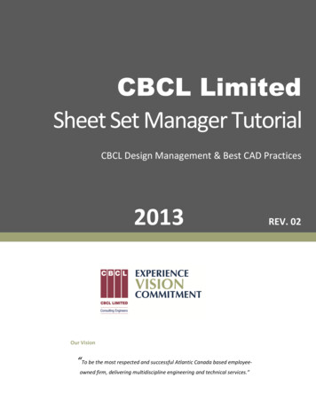
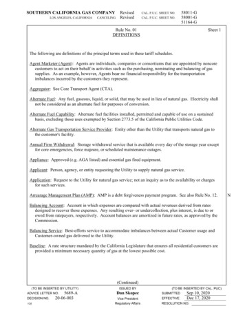
Half rafterHalf rafterspanspanrafterrafteroverhangoverhangRoof Area SupportedRoof Area Supported(Post A) (Post A) (Post B) (Post B) beamHalf beambeamHalf beamoverhangspanoverhangspanHalf beamHalf beamspanspanHalf beamHalf beamspanspanFigure 2 - Roof area supported by postsTIMBER POSTSINSTALLING POSTS IN GROUNDTable 1 lists the sizes for timber posts.Sawn timber posts should preferably be fixed to hot dippedgalvanised steel stirrups set in concrete. A minimum clearance of 75mm shall be provided between the top of the concrete footing orpaving and the bottom of the post as a termite inspection zone.TABLE 1 - TIMBER POSTS - SUPPORTING PERGOLAOR CARPORT ROOF (MAX. 10 KG/M2)Roof AreaSupported(m2)MemberSize (mm)51020Maximum Post Height(mm)UnseasonedCypress F575 x 75100 x 1003400480024004200N/S3000Seasoned TreatedPine F770 x 7090 x 903500480025004100N/S2900UnseasonedHardwood F1475 x 75100 x 100480048003400480024004200Treated PineRounds F8100 dia125 dia150 dia480048004800340048004800N/S36004800ATTACHING POSTS TO TIMBER DECKSPosts supporting roofs or pergolas over timber decks shall occurdirectly over deck supports. Posts supporting decks and roofs maybe continuous from ground to roof beams with deck bearers fixedto sides of posts (refer Technical Data Sheet 4). Alternatively, postssupporting roofs shall be fixed to bearers with the required fixingtype listed in Tables 3 and 4.Posts embedded in the ground shall be provided with stainless steelmesh socks (TermiMesh) or alternatively the surrounding groundshall be chemically treated.Holes for embedded posts shall be filled with 100 mm depth ofcoarse gravel (to allow water to drain) before backfilling withconcrete or rammed earth. Top of backfill shall be sloped away fromposts to shed water. Footings to be engineer designed for bothbearing and uplift.Hot dippedHot dippedgalvanisedstirrupgalvanised stirrupTop of footingTopawayof footingsloppedfromsloppedpost awayfrom postConcreteConcretefootingorfooting orrammedrammedearth backfillearth backfill75 mm75 mm100 mm100 mmConcrete footingConcrete footing(a) Fixed to stirrupCourse gravel laid atCoursegravelthe baseof thepostlaid atthe base of the post(b) Embedded in groundFigure 3 - Installing posts TIMBER QUEENSLAND LIMITED TECHNICAL DATA SHEET 19 PERGOLAS AND CARPORTS Revised March 2014Page 2
PERGOLA OR CARPORT BEAMSTables 2L and 2H list the sizes and spans for pergola or carport beams in low wind speed and higher wind speed areas.TABLE 2L - PERGOLA OR CARPORT BEAMS - (WIND CLASSIFICATIONS N1, N2, N3 AND C1)MemberSize150030004500Roof Load Width60001500Maximum Beam Span (mm)Single Span300045006000Continuous SpanUnseasonedCypressF5100 x 50100 x 75125 x 50125 x 75150 x 50150 x 75175 x 50175 x 75200 x 50200 x sonedTreated PineF790 x 45120 x 45140 x 452/140 x 35190 x 452/190 x 35240 x 452/240 x nedHardwoodF14100 x 50100 x 75125 x 50125 x 75150 x 50150 x 75175 x 50175 x 75200 x 50200 x 75250 x 50250 x 22002800270032003100370038004700300045006000Note: Maximum overhang shall be 25% of the actual backspan.TABLE 2H - PERGOLA OR CARPORT BEAMS - (WIND CLASSIFICATIONS N4 AND C2)4500Roof Load Width60001500Maximum Beam Span (mm)MemberSize15003000UnseasonedCypressF5100 x 50100 x 75125 x 50125 x 75150 x 50150 x 75175 x 50175 x 75200 x 50200 x SN/SN/SN/SN/SN/SN/S1600N/S1800SeasonedTreated PineF790 x 45120 x 45140 x 452/140 x 35190 x 452/190 x 35240 x 452/240 x dF14100 x 50100 x 75125 x 50125 x 75150 x 50150 x 75175 x 50175 x 75200 x 50200 x 75250 x 50250 x 0210027002600300031003800Single SpanContinuous SpanNote: Maximum overhang shall be 25% of the actual backspan. TIMBER QUEENSLAND LIMITED TECHNICAL DATA SHEET 19 PERGOLAS AND CARPORTS Revised March 2014Page 3
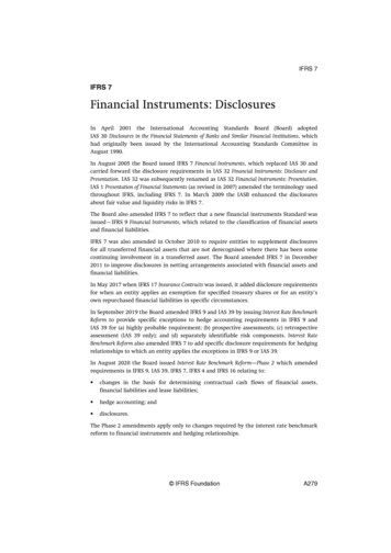
Roof Load WidthRoof Load WidthRoof Load WidthRoof Load Widthfor Beam Afor Beam d WidthRoofLoad WidthspanAspan for BeamspanOverhangfor BeamBfor Beam Afor Beam panOverhangMULTIPLE BEAMSWhere covered by a roof, double beams may be either spaced apart(with a solid timber separating block at mid-span) or nail laminatedtogether to form a single beam. Fully exposed double beams inunroofed pergolas shall be spaced.Beam BBeam BBeamBeamBBBeam ABeam ABeamBeamAAPostPostPostPostSpacer blockSpacer blockSpacerSpacerblockblockFigure 4 - Roof load widthDouble nailboth endsDoubleatnailDoublenailatbothendsDouble nailatatbothbothendsendsFIXING BEAMS TO POSTSBeams shall be fixed to posts as listed in Tables 3 & 4. Where beamsare housed into posts, a minimum of 35 mm of post shall remain.Alternatively, beams can be fixed to posts with proprietary galvanisedsteel brackets in accordance with manufacturer’s recommendations.Figure 5 - Multiple beamsTABLE 3 - FIXING TYPES - POSTS TO BEARERS OR BEAMS35 mm (min.)Fixing Type35 mm (min.)35 mm (min.)2 boltP1Ø35 mm6 boltØ (min.)Ø2 bolt Ø5 boltP26 bolt ØØ52 bolt Ø4 boltP36 bolt ØboltØØ6 bolt Ø452boltP4boltØØ45boltBolts are per Table4 bolt ØPostBolts are per TableBolts are per TablePostBolts are per TablePostPost4 bolt Ø4 bolt Ø5 bolt Ø6 bolt Ø54 bolt Ø2 bolt ØboltØØ6 bolt Ø254boltboltØØ6 bolt 35Ø mm (min.)25bolt6 bolt Ø2 bolt Ø35 mm (min.)35 mm (min.)35 mm (min.)Bolts asBolts as per tableBoltstableasperBolts asper tableper tableDescription1/M10 bolt1/M12 bolt2/M10 bolts2/M12 boltsP5P6P72/M10 bolts2/M12 bolts2/M16 bolts150x90x10 mmM.S.mmangle150x90x10150x90x10M.S.angle mm150x90x10mmM.S. angleM.S. angleTABLE 4L - FIXING REQUIREMENTS - POSTS TOBEARERS OR BEAMS (WIND CLASSIFICATIONS N1,N2, N3 AND C1)TABLE 4H - FIXING REQUIREMENTS - POSTS TOBEARERS OR BEAMS (WIND CLASSIFICATIONS N4AND C2)Roof Area Supported (m2)Roof Area Supported (m2)55101520Fixing types permitted101520Fixing types permittedUnseasoned Cypress F5(J3)P4P5P5P6P7Unseasoned Cypress F5(J3)P5P6P7P7Seasoned Treated Pine F7(JD4)P3P5P5P6P6Seasoned Treated Pine F7(JD4)P5P6P7P7Unseasoned Hardwood F14(J2)P1P5P5P6P7Unseasoned Hardwood F14(J2)P4P5P6P7P7Note: For roof area supported refer Figure 2.Note: For roof area supported refer Figure 2. TIMBER QUEENSLAND LIMITED TECHNICAL DATA SHEET 19 PERGOLAS AND CARPORTS Revised March 2014Page 4
PERGOLA OR CARPORT RAFTERSTables 5L and 5H list the sizes and spans for pergola or carport rafters in low wind speed and higher wind speed areas.TABLE 5L - PERGOLA OR CARPORT RAFTERS - (WIND CLASSIFICATION N1, N2, N3 AND C1)Rafter SpacingMember Size600900600Maximum Rafter Span (mm)Single SpanUnseasonedCypressF5SeasonedTreated PineF7UnseasonedHardwoodF14100 x 38100 x 50125 x 38125 x 50150 x 38150 x 50175 x 38175 x 50200 x 38200 x 5090 x 3590 x 45120 x 35120 x 45140 x 35140 x 45190 x 35190 x 45240 x 35240 x 45100 x 38100 x 50125 x 38125 x 50150 x 38150 x 50175 x 38175 x 50200 x 38200 x 50250 x 38250 x 004600500052005600580067007000900Continuous 00500055005900630067007100720072007200Notes: For unnotched rafters, maximum overhang shall be 25% of the actual backspan.For notched rafters, overhang limits shall be in accordance with AS 1684.TABLE 5H - PERGOLA OR CARPORT RAFTERS - (WIND CLASSIFICATION N4 AND C2)Member SizeRafter Spacing900600Maximum Rafter Span (mm)600Single SpanUnseasonedCypressF5SeasonedTreated PineF7UnseasonedHardwoodF14100 x 38100 x 50125 x 38125 x 50150 x 38150 x 50175 x 38175 x 50200 x 38200 x 5090 x 3590 x 45120 x 35120 x 45140 x 35140 x 45190 x 35190 x 45240 x 35240 x 45100 x 38100 x 50125 x 38125 x 50150 x 38150 x 50175 x 38175 x 50200 x 38200 x 50250 x 38250 x 004600500052005600580067007000900Continuous 00440046005300550063006300720072007200Notes: For unnotched rafters, maximum overhang shall be 25% of the actual backspan.For notched rafters, overhang limits shall be in accordance with AS 1684. TIMBER QUEENSLAND LIMITED TECHNICAL DATA SHEET 19 PERGOLAS AND CARPORTS Revised March 2014Page 5
ATTACHING PERGOLA OR CARPORT TO HOUSEProvided the wall frame of the house is checked to ensure it cancarry the additional load, pergolas and carports can be attached tothe wall (refer method W1).TABLE 6 - ADDITIONAL UPLIFT FORCE FROMCARPORT/PERGOLAWind ClassificationAdditional uplift (kN) for carportor pergola rafter spans1800 2400 3000 3600 4200Provided the wall frame is adequate, and the house roof frame andtie-down fixings are checked and increased where necessary toensure it can carry the additional load, and withstand the additionaluplift (refer Table 6), pergolas and carports can be attached tofascias/eaves.N1 & 20.91.21.41.72.0N3C11.41.92.32.83.3Pergolas and carports may be attached to the fascias/eaves bymethods F1, F2 and F3 as allowed in Table 7L and 7H.-N4C22.12.33.54.24.9 The maximum overhang of house rafters or trusses shall notexceed 750 mm from outside of top plate to end of rafter/ truss.F or sheet roofed houses with 900 mm rafter spacing in windclassification N4 or C2, the minimum size of F5 or MGP 10 rafters(or top chords) shall be 90 x 45 mm. In all other cases, the minimumsize of house rafters (or top chords) shall be 90 x 35 mm.Metal Fascia100 x 38Continuous Ledgerfixed to noggings with2/75 x No. 14 Type 17Roof Batten Screensat 600 crs.Carport rafters to befixed to ledger withjoist hangers as forMethods F1, F2 & F3. Timber fascias shall be minimum 190 x 25 mm.M etal fascias shall be stiffened with 150 x 50 mm nogging and 100x 38 mm ledger as shown on detail.P ergola or carport rafters may be notched up to 1/3 their depth.M aximum pergola or carport rafter spacing shall be 900 mm.150 x 50 (140 x 45) Nogging fixed betweeneach rafter / truss with 2/75 x 3.15Ø nails orframing anchor each end.Figure 6 - Metal FasciasD/3 (max)Ensure properly sealed / primedbefore fixing in place.45 (min)D/3 (max)Figure 7 - Maximum notching TIMBER QUEENSLAND LIMITED TECHNICAL DATA SHEET 19 PERGOLAS AND CARPORTS Revised March 2014Page 6
HangerFascia fixed torafter / truss ends with3/75 x 3.15 groovedflat head nailsSoffit TrimerCheck existingtie-down and wall framefor adequacyTrimmer fixed to ledger with2/framing anchors 4/30 x 2.8 Ø nailsto trimmer and 4/30 x 2.8 Ø nails toledger each legFascia fixed torafter / truss ends with1/75 Batten Screw plus2/75 x 3.15 Ø nailsCarport / PergolaRafterLedger 70 x 35 F5 (MGP10)fixed to each stud with 1/75No. 14 Type 17 Batten ScrewJoist Hanger 3/30 x 2.8 Ø nails eachside to rafter, 4/30 x 2.8 Ø nailseach leg to fascia.Check existingtie-down and wall framefor adequacyTimber Fascia190 x 25 (min)Trimmer 70 x 35 F53/75 x 3.15 Ø nailsJoist Hanger 3/30 x 2.8 Ø nails eachside to rafter, 4/30 x 2.8 Ø nailseach leg to fascia.(c) Method F3(a) Method F1Flash/seal asappropriate90 x 35 F8 (MGP12) Stiffener fixed to top chordwith 75 x 3.15 Ø nails staggered at 200 crs or75 x No. 14 Type 17 Batten Screws at 400 crsHangerFascia fixed totop chord/rafter ends with1/75 No 14 Type 17 Screwplus 2/75 x 3.15 Ø nailsTimber Fascia190 x 25 (min)Remove existing fasciaCarport / PergolaRafterCheck existingwall frame foradequacy for extraroof dead loadSoffit TrimerCheck existingtie-down and wall framefor adequacyCarport / PergolaRafterCarport / PergolaRafter2/framing anchors4/30 x 2.8 Ø nails to each legLedger 90 x 35 F5 (MGP10)fixed to each stud or lintel with1/75 No. 14 Type 17 Batten ScrewJoist Hanger 3/30 x 2.8 Ø nails eachside to rafter, 4/30 x 2.8 Ø nailseach leg to fascia.AlternativeJoist Hanger(d) Method W1(b) Method F2Figure 8 - Methods for attaching pergola and carport to houseTABLE 7L - ATTACHING PERGOLA OR CARPORT TO HOUSE (WIND CLASSIFICATIONS N1, N2, N3 AND C1)House RoofRoof Type(rafter spacing)Rafter/TrussStress GradeF5 (MGP 10)Tile(600 mm)F8 (MGP 12) or betterF5 (MGP 10)Sheet(900 mm)F8 (MGP 12) or betterAcceptable method of attachmentPergola/carport rafter span W1Note: Method F1 may also be used (in wind classifications N1 and N2 only) for F5 (MGP10) pergola or carport rafters up to 2700 mm span, and for F8 (MGP12) orbetter pergola or carport rafters up to 4200 mm span.TABLE 7H - ATTACHING PERGOLA OR CARPORT TO HOUSE (WIND CLASSIFICATIONS N4 AND C2)House RoofRoof Type(rafter spacing)Tile(600 mm)Sheet(900 mm)Rafter/TrussStress GradeF5 (MGP 10)F8 (MGP 12) or betterF5 (MGP 10)F8 (MGP 12) or betterAcceptable method of attachmentPergola/carport rafter span (mm)Up to 2700Exceeding 2700F3W1F3W1F3W1F3W1 TIMBER QUEENSLAND LIMITED TECHNICAL DATA SHEET 19 PERGOLAS AND CARPORTS Revised March 2014W1W1W1W1Page 7
FIXING RAFTERS TO BEAMS OR LEDGERSPergola and carport rafters shall be fixed to beams with the fixing type listed in Tables 8 and 9.TABLE 8 - FIXING TYPES - RAFTERS TO PERGOLA OR CARPORT BEAMSFixing TypeDescriptionFraming anchorsFraminganchorsasper dianailsas 4/2.8in4/2.8eachdialegnailsin eachleglegin each30x0.8 mm strap with30x0.8mmstrap with3/2.8mmØ ch end as per tableeachendendas pertableeachas pertableRafter hickness35Raftermm (min.)35 nalnailingnailingnailing75x50x5 mm MS angle75x50x5mmMS orwith1/M1040 mmNo14Type17screwstorafteras40 40mmmmNo14Type 17 17screwstoNo14rafterTypeaspertablescrewsto rafter asscrewspertableto rafter asperpertabletableR11/galvanised framing anchorR22/galvanised framing anchorsR31/30 x 0.8 mm galvanised iron strapR42/30 x 0.8 mm galvanised iron strapR5Fixings to each leg1/No.14 Type 17 screwR62/No.14 Type 17 screwR71/M10 boltR81/M10 boltR91/M12 bolt50 mm No1450 mmNo14Type17 No14screws50 50mmmmNo14Type17 screwstobeamType17screwsType17 screwstobeamaspertableto beambeamastopertableas pertableas pertableBolts as per tableBolts as per tableBoltsas pertableBoltsas pertableTABLE 9L - FIXING REQUIREMENTS - RAFTERSTO PERGOLA OR CARPORT BEAMS (WINDCLASSIFICATIONS N1, N2, N3 AND C1)TABLE 9H - FIXING REQUIREMENTS - RAFTERSTO PERGOLA OR CARPORT BEAMS (WINDCLASSIFICATIONS N4 AND C2)Roof Area Supported (m2)Roof Area Supported (m2)246Fixing types permitted246Fixing types permittedUnseasoned Cypress F5(J3)R1R3R5R8R4R6R8Seasoned Treated Pine F7(JD4)R1R3R5R8R4R6R8R9Unseasoned Hardwood F14(J2)R1R3R5R8R2R4R6R8R4R6R8Unseasoned Cypress F5(J3)R2R4R6R8R8R8Seasoned Treated Pine F7(JD4)R2R4R6R8R9R9Unseasoned Hardwood F14(J2)R2R3R5R8R4R6R8R8R8 TIMBER QUEENSLAND LIMITED TECHNICAL DATA SHEET 19 PERGOLAS AND CARPORTS Revised March 2014Page 8
ROOF BATTENSTables 10L and 10H list the sizes and spans for roof battens in low wind speed and higher wind speed areas.TABLE 10L - ROOF BATTENS - SUPPORTING LIGHTWEIGHT ROOF (MAX. 10 KG/M2)(WIND CLASSIFICATIONS N1, N2, N3 AND C1)Batten Spacing300Member Size(d x b)6009001200Maximum Batten Span (mm)(rafter spacing)Unseasoned Cypress F5(J3)38 x 7550 x 7575 x 3875 x Seasoned Treated Pine F7(JD4)35 x 7045 x 7070 x 3570 x Unseasoned Hardwood F14(J2)25 x 5038 x 5038 x 7550 x 9001200Note: Maximum overhang shall be 25% of the actual backspan.TABLE 10H - ROOF BATTENS - SUPPORTING LIGHTWEIGHT ROOF (MAX. 10 KG/M2)(WIND CLASSIFICATIONS N4 AND C2)Batten Spacing300Member Size(d x b)600Maximum Batten Span (mm)(rafter spacing)Unseasoned Cypress F5(J3)38 x 7550 x 7575 x 3875 x Seasoned Treated Pine F7(JD4)35 x 7045 x 7070 x 3570 x Unseasoned Hardwood F14(J2)25 x 5038 x 5038 x 7550 x Note: Maximum overhang shall be 25% of the actual backspan. TIMBER QUEENSLAND LIMITED TECHNICAL DATA SHEET 19 PERGOLAS AND CARPORTS Revised March 2014Page 9
FIXING BATTENS TO RAFTERSPergola and carport roof battens shall be fixed to rafters with nails, screws or framing anchors as listed in Tables 11 and 12.25x50 mmbattenBATTENS TO RAFTERSTABLE 11 - FIXING TYPES- ROOF25x50 mm battenNails as25x50 mmperbattentableFixing TypeDescriptionB11/65 x 3.05 mm dia. nail (deformed shank)B21/75 x 3.05 mm dia. nail (deformed shank)B32/75 mm long nails (deformed shank)B41/75 mm long No.14 Type 17 screwsB52/75 mm long No.14 Type 17 screwsB61 framing anchorB72 framing anchors (each side of batten)Nails asper tableNails asper table38 x 75 or38x50 mm batten38 x 75 or38x50 mmNailsbattenor38 x 75 orscrews38x50 mm battenasper tableNails orscrews asNailstableorperTwo nails or screws shall be usedscrews asonly with 75mm wide battenper tableTwo nails or screws shall be usedonly with 75mm wide battenTwo nails or screws shall be usedonly with 75mm wide battenFraminganchors4/2.9 mm dia.Framingnails toanchorseach legFraming4/2.9mm dia.anchorsnails to4/2.9 legmm dia.eachnails toeach legTABLE 12L - FIXING REQUIREMENTS - ROOFBATTENS TO RAFTERS (WIND CLASSIFICATIONS N1,N2, N3 AND C1)TABLE 12L - FIXING REQUIREMENTS - ROOFBATTENS TO RAFTERS (WIND CLASSIFICATIONS N4AND C2)Roof Area Supported (m2)0.360.540.811.08Fixing types permittedRoof Area Supported (m2)1.44UnseasonedCypress F5(J3)B1B3B4B6B3B4B6B4B6B4B6B4B7Seasoned TreatedPine F7(JD4)B3B4B6B4B6B4B6B4B6B4B7UnseasonedHardwood 8Fixing types permitted1.44UnseasonedCypress F5(J3)B3B4B6B4B6B4B7B5B7B5Seasoned TreatedPine F7(JD4)B4B6B4B6B4B7B5B7B5UnseasonedHardwood F14(J2)B3B4B6B3B4B6B4B6B4B6B5B7 TIMBER QUEENSLAND LIMITED TECHNICAL DATA SHEET 19 PERGOLAS AND CARPORTS Revised March 2014Page 10
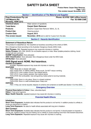
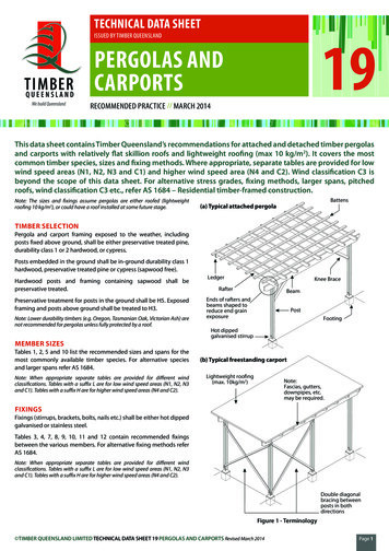
Bracing fixedto underside of rafters(a) To underside of raftersThe greater thesedistances the moreeffective the brace300mm min.100 x 50mm or90 x 45mmKnee Brace300 mm min.M12 bolts12 mm dia hot dippedgalvanised bolts(c) Knee brace(b) Between postsFigure 9 - BracingBRACINGROOFINGCarports and pergolas will require bracing to prevent lateralmovement.Roof sheeting, gutters, downpipes, drainage etc. shall be installedin accordance with manufacturers recommendations and LocalAuthority requirements.For pergolas attached to the house, bracing shall be either:(a) Double diagonal 100 x 50 mm hardwood or 90 x 45 treated pinebraces fixed to the underside of rafters with each brace fixed toeach rafter with 75 mm No. 14 Type 17 batten screws or two 75 x3.15 mm galvanised nails, or(b) Double diagonal 100 x 50 mm hardwood or 90 x 45 mm treatedpine braces fixed between a pair of posts parallel to the wall, withbraces bolted together at the crossing and to the posts at eachend with 12 mm dia. hot dipped galvanised bolts, or(c) A pair of opposing knee braces to a pair of posts parallel to thewalls. Knee braces shall be 100 x 50 mm hardwood or 90 x 45 mmtreated pine, fixed at approximately 45 and bolted to beams andposts with two 12 mm dia. hot dipped galvanised bolts.Freestanding pergolas and carports require double diagonal bracingbetween posts in both directions (i.e. at right angles) as described in(b) above. TIMBER QUEENSLAND LIMITED TECHNICAL DATA SHEET 19 PERGOLAS AND CARPORTS Revised March 2014Page 11
FINISHINGAll pergolas and carports shall have an applied finish as protectionagainst the weathering effects of sun and rain and improve durability.Note: Unprotected timber exposed to the weather will fade to a silver-greycolour and could distort, split or develop surface checking.One coat of a water repellent preservative or an oil based primer shallbe applied to concealed joints, laps etc. prior to fixing. Additionalcoats of the selected finish shall be applied (to manufacturer’sinstructions) to all surfaces after construction.The following finish types are available:Clear Finishes and Water Repellent Preservatives (WRP)These are generally water repellent materials (waxes, resins, etc.) in alight organic solvent base. They often also contain chemicals whichinhibit decay. Water repellent preservatives provide good protectionagainst moisture and are recommended as a priming coat for othercoatings. The compatibility of WRP with other coatings shouldhowever be checked. Generally two weeks are required betweenapplication of WRP and other finishes.MaintenanceReapplication of finishes will be required at regular intervals,depending on finish type and degree of exposure. Before recoating,all surfaces shall be thoroughly cleaned and loose dirt, grit, foliageetc. removed. For some finishes, surfaces may also require sanding.Recoating shall be carried out in accordance with the manufacturer’srecommendations.SAFE WORKINGWorking with timber produces dust particles. Protection of theeyes, nose and mouth when sanding, sawing and planing is highlyrecommended. Refer to tool manufacturers for safe workingrecommendations for particular items of equipment.DISPOSAL OF OFFCUTS AND WASTEFor any treated timber, do not burn offcuts or sawdust. Preservativetreated offcuts and sawdust should be disposed of by approvedlocal authority methods.WRP and other clear finishes do not provide long term protectionagainst the UV effects from the sun. When used on their own theyrequire reapplication at about six monthly intervals.Note: Clear polyurethane finishes can breakdown under UV exposure and arenot recommended for external use.PaintsGood quality, light coloured opaque paint finishes provide the bestprotection against weathering, however they obscure the naturalcolour and grain of the timber. Pale colours are recommended toreduce checking and decay.Recoating is necessary every seven to ten years depending uponexposure. Additional preparation (sanding, repriming etc.) isfrequently necessary.Oils/StainsOils and stains are available which provide a relatively natural, semitransparent, protective finish. Stains are often available with mouldinhibiting additives.Stains with light coloured pigments are recommended as theyabsorb less heat and only slightly change the natural colour of thetimber.Reapplication is generally necessary every two to five yearsdepending upon the amount of pigment included, and the degreeof exposure. Apart from cleaning, no additional surface preparationis generally required.Timber Queensland LimitedACN 092 686 756 ABN 50 092 686 75630 Boothby Street, KedronBrisbane Queensland 4031Phone (07) 3358 7900Fax(07) 3358 7999PO Box 231, Kedron Qld and.com.auWhilst every effort is made to ensure the accuracy of advice given, Timber Queensland Limited cannot accept liability for loss or damage arising from the use of the information supplied. TIMBER QUEENSLAND LIMITED TECHNICAL DATA SHEET 19 PERGOLAS AND CARPORTS Revised March 2014Page 12
PERGOLA OR CARPORT BEAMS Tables 2L and 2H list the sizes and spans for pergola or carport beams in low wind speed and higher wind speed areas. TABLE 2L - PERGOLA OR CARPORT BEAMS - (WIND CLASSIFICATIONS N1, N2, N3 AND C1) Member Size Roof Load Width 1500 3000 4500 6000 1500 3000 4500 6000 Maximum Beam Span (mm) Single Span Continuous Span .