Transcription
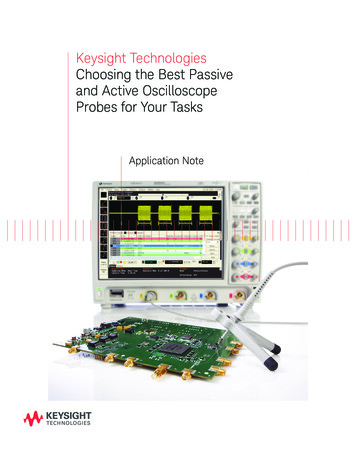
Keysight TechnologiesChoosing the Best Passiveand Active OscilloscopeProbes for Your TasksApplication Note
IntroductionThe passive voltage probe is the most commonly used type ofscope probe todaySelecting the right probe for your application is the first step toward making reliable oscilloscopemeasurements. Although you can choose from a number of different types of oscilloscope probes,they fall into two major categories: passive and active. Passive probes do not require external probepower. Active probes do require external probe power for the active components in the probe, suchas transistors and amplifiers, and provide higher bandwidth performance than passive probes.Each category offers many different types of probes, and each probe has an application for whichit performs best.Passive ProbesThe most common type of scope probe today is the passive voltage probe. Passive probes can bedivided into two main types: high-impedance-input probes and low-impedance resistor-dividerprobes. The high-impedance-input passive probe with a 10:1 division ratio is probably the mostcommonly used probe today. This probe is shipped with most low- to mid-range oscilloscopes today.The probe tip resistance is typically 9 MΩ, which gives a 10:1 division ratio (or attenuation ratio) withthe scope’s input when the probe is connected to the 1 MΩ input of a scope. The net input resistanceseen from the probe tip is 10 MΩ. The voltage level at the scope’s input is then 1/10th the voltage levelat the probe tip, which can be expressed as follows: Vscope Vprobe * (1 MΩ/ (9 MΩ 1 MΩ))
03 Keysight Choosing the Best Passive and Active Oscilloscope Probes for Your Tasks - Application NotePassive ProbesCompared to active probes, passiveprobes are more rugged and lessexpensive. They offer a wide dynamicrange ( 300 V for a typical 10:1 probe)and high input resistance to match ascope’s input impedance. However,high-impedance-input probes imposeheavier capacitive loading and havelower bandwidths than active probesor low-impedance (z0) resistor-dividerpassive probes.The low-impedance resistor-dividerprobe has either 450 Ω or 950 Ω inputresistance to give 10:1 or 20:1 attenuation with the 50 Ω input of the scope.The input resistor is followed by a 50Ω cable that is terminated in the 50 Ωinput of the scope. Remember that thescope must have a 50 Ω input to usethis type of probe. The key benefitsof this probe include low capacitiveloading and very high bandwidth—inthe range of a couple of GHz—whichhelps to make high-accuracy timingmeasurements. In addition, this is alow-cost probe compared to an activeprobe in a similar bandwidth range. Youwould use this probe in applicationssuch as probing electronic circuitlogic (ECL) circuits, microwave devicesor 50 Ω transmission lines. The onecritical trade-off is that this probe hasrelatively heavy resistive loading, whichcan affect the measured amplitude ofthe signal.Cable9 ut1 MΩOscilloscopeInputCapacitanceFigure 2. High-impedance passive probes offer a rugged and inexpensive solution for general-purposeprobing and troubleshooting.Probe Tip50 Ω CableOscilloscope Input1 MΩ450 Ω950 ΩFigure 3. The low-impedance resistor-divider probe features low capacitive loading and widebandwidth.50 Ω
04 Keysight Choosing the Best Passive and Active Oscilloscope Probes for Your Tasks - Application NoteActive ProbesIf your scope has more than 500MHz of bandwidth, you are probablyusing an active probe—or shouldbe. Despite its high price, the activeprobe is the tool of choice when youneed high-bandwidth performance.Active probes typically cost more thanpassive probes and feature limitedinput voltage but, because of theirsignificantly lower capacitive loading,they give you more accurate insightinto fast signals.By definition, active probes requireprobe power. Many modern activeprobes rely on intelligent probeinterfaces that provide power andserve as communication links betweencompatible probes and the scope.Typically the probe interface identifiesthe type of probe attached and sets upthe proper input impedance, attenuation ratio, probe power and offsetrange needed.Typically you would choose asingle-ended active probe for measuring single-ended signals (a voltagereferenced to ground) and differentialactive probes for measuring differentialsignals (a plus voltage versus a minusvoltage). The effective ground planebetween the signal connections indifferential probes is more ideal thanmost of the ground connections insingle-ended probes. This groundplane effectively connects the probetip ground to the device-under-test(DUT) ground with very low impedance. Therefore differential probes canmake even better measurements onsingle-ended signals than single-endedprobes can. The Keysight Technologies,Inc. InfiniiMax 1130A Series probingsystem allows either differential orsingle-ended probing with a singleprobe amplifier by using interchangeable probe heads that are optimizedfor hand browsing, plug-on socketconnections or solder-in connections.Figure 4. Many modern active probes rely on intelligent probe interfaces that provide power and serveas communication links between compatible probes and the scope.Figure 5. The InfiniiMax probing system offers a variety of single-ended and differential probe headaccessories for a cost-effective single-ended and differential probing solution.
05 Keysight Choosing the Best Passive and Active Oscilloscope Probes for Your Tasks - Application NoteBandwidth ConsiderationsHigher bandwidth is a clear advantageof active probes over passive probes.One issue probe users often overlookis the effect of the connection to thetarget, which is called “connectionbandwidth.” Even though a particularactive probe may have an impressivebandwidth specification, the publishedspecified performance may begiven for ideal probing conditions.In a real-world probing situation,which would include using probingaccessories to attach to the probe tips,the active probe’s performance maybe much worse than the publishedspecified performance. The real-worldperformance of an active probingsystem is dominated primarily bythe “connection” system. Parasiticcomponents to the left of the pointlabeled VAtn in Figure 5 are the drivingfactors in determining the performanceof a real-world active probing systemin high-frequency applications.As an example, Keysight’s N2796A2 GHz single-ended active probeprovides 2 GHz of bandwidth witha probe tip and a 2 cm-long offsetground. With this best-case setup, youget 2 GHz of probe bandwidth. If youtake the tip and ground off and replacethem with a 10 cm dual-lead adapter,the probe bandwidth drops to 1 GHz.With additional clips attached to thedual-lead adapter, the probe bandwidth is further reduced to 500 MHz.So the key here is that shorter inputleads improve probe performance.V InLength affects bandwidthLs/4V InLg/4Length doesnot affects bandwidthC Amp/4Ls/2Ls/4Cc/2Cc/2 V AtnLg/2V Atn/54R/SR/51C AmpLg/450Zo 5050V OutV Out-V Atn/10Figure 6. Parasitic components to the left of the point labeled VAtn are the driving factors in determining the performance of a real-world active probing system in high-frequency applications.Figure 7. You will achieve higher probe bandwidths with shorter leads.
06 Keysight Choosing the Best Passive and Active Oscilloscope Probes for Your Tasks - Application NoteProbe Loading EffectAt DC and low frequency ranges, theprobe’s input impedance starts out atthe rated input resistance, say 10 MΩfor a 10:1 passive probe, but as thefrequency goes up, the input capacitance of the probe starts to become ashort, and the impedance of the probestarts to drop. The higher the inputcapacitance, the faster the impedanceslope drops.500 MHzPassive Probe10 MΩ, 9.5 pF2 GHzActive Probe1 MΩ, 1 pF1.E 08Impedance (ohm)Now let’s discuss a probe’s inputimpedance and input loading. Manypeople think that probe input impedance is a constant number. You mighthear that the probe has a kΩ, MΩ, oreven a 10 MΩ input impedance, butthat isn’t constant over frequency.Input impedance decreasesover frequency1.E 071.E 061.E 051.E 04 2.5 kΩ1.E 03 150 kΩ1.E 0270 MHz1.E 011.E 001.E 01 1.E 02 1.E 03 1.E 04 1.E 05 1.E 06 1.E 07 1.E 08 1.E 09 2E 09Frequency (Hz)Figure 8. At a crossover point of 10 kHz and beyond, the input impedance of the activeprobe is higher than that of the passive probe.Figure 8 shows a comparison betweena 500 MHz passive probe and a 2GHz active probe. You’ll see that at acrossover point of 10 kHz and beyond,the input impedance of the activeprobe is higher than that of the passiveprobe. Higher input impedance meansless loading on the target signal, andless loading means less effect on orless disruption of the signal.At about 70 MHz bandwidth on thechart, the input impedance of thepassive probe decreases to 150 Ω,while the input impedance of the activeprobe is about 2.5 kΩ. The differencebetween them is significant. If, forexample, you had a system that had50 Ω or 100 Ω source impedance, thepassive probe would have a significantly higher effect on the signal due toprobe loading.In that frequency range, connectingthe passive probe is like hanging a150 Ω resistor on your circuit. If youcan tolerate that, this passive probe isgoing to be fine. If you can’t toleratethat, then this probe would be an issue,and you’d be better off choosing aprobe with higher impedance at a highfrequency range, like an active probe.Figure 9. Signal edge speeds measured with a 2 GHz active probe (yellow trace) anda 500 MHz passive probe (red trace).Figure 9 above is an example of anactual signal measured with twodifferent probes. The green traceshows the 1.1 nsec signal edge speedwith no probe attached. That turnsout to be a 300 MHz bandwidth in thatsignal ( 0.35/1.1 nsec). With a 2 GHzactive probe attached to measure the1.1 nsec signal, you can’t even see thedifference between the original signaland the probed signal, as shown bythe yellow trace underneath the greentrace. Obviously the active probe didnot disturb the signal on the targetmuch.If you take the same signal and attacha 500 MHz passive probe, the edgespeed of the signal on the target nowmeasures 1.5 nsec. The passive probeactually disrupted the signal on thetarget and slowed it down.
07 Keysight Choosing the Best Passive and Active Oscilloscope Probes for Your Tasks - Application NoteConclusionWhen considering the right measurement tools for scope applications,probing is often an afterthought. Manyengineers select the scope first basedon the bandwidth, sample rate andchannel count needed, and then worryabout how to get the signal into thescope later. But selecting the rightprobe for your application and usingthe probe correctly is the first steptoward reliable scope measurements.A passive probe is a safe choice forgeneral-purpose probing and troubleshooting; but for high-frequencyapplications, an active probe gives youmuch more accurate insight into fastsignals. Although many active probeson the market have an impressivebandwidth specification, rememberthat the real-world performance of anactive probe is dominated primarilyby how you connect the probe to thetarget. A simple rule of thumb is thata shorter input lead is better if you’relooking for high-fidelity measurements.Keysight Technologies OscilloscopesMultiple form factors from 20 MHz to 90 GHz Industry leading specs Powerful applications
08 Keysight Choosing the Best Passive and Active Oscilloscope Probes for Your Tasks - Application NoteEvolving Since 1939Our unique combination of hardware, software, services, and people can help youreach your next breakthrough. We are unlocking the future of technology.From Hewlett-Packard to Agilent to tA personalized view into the information most relevant to you.http://www.keysight.com/find/emt product registrationRegister your products to get up-to-date product information andfind warranty information.Keysight Serviceswww.keysight.com/find/serviceKeysight Services can help from acquisition to renewal across yourinstrument’s lifecycle. Our comprehensive service offerings—onestop calibration, repair, asset management, technology refresh,consulting, training and more—helps you improve product qualityand lower costs.Keysight Assurance Planswww.keysight.com/find/AssurancePlansUp to ten years of protection and no budgetary surprises to ensureyour instruments are operating to specification, so you can rely onaccurate measurements.Keysight Channel Partnerswww.keysight.com/find/channelpartnersGet the best of both worlds: Keysight’s measurement expertise andproduct breadth, combined with channel partner convenience.www.keysight.com/find/probesFor more information on KeysightTechnologies’ products, applications orservices, please contact your local Keysightoffice. The complete list is available azilMexicoUnited States(877) 894 441455 11 3351 7010001 800 254 2440(800) 829 4444Asia PacificAustraliaChinaHong KongIndiaJapanKoreaMalaysiaSingaporeTaiwanOther AP Countries1 800 629 485800 810 0189800 938 6931 800 11 26260120 (421) 345080 769 08001 800 888 8481 800 375 81000800 047 866(65) 6375 8100Europe & Middle rlandUnited Kingdom0800 0011220800 585800800 5232520805 9803330800 62709991800 8327001 809 343051800 599100 32 800 585800800 02332008800 5009286800 0001540200 8822550800 805353Opt. 1 (DE)Opt. 2 (FR)Opt. 3 (IT)0800 0260637For other unlisted 7)DEKRA CertifiedISO9001 Quality Management Systemwww.keysight.com/go/qualityKeysight Technologies, Inc.DEKRA Certified ISO 9001:2015Quality Management SystemThis information is subject to change without notice. Keysight Technologies, 2017Published in USA, December 2, 20175990-8576ENwww.keysight.com
Dec 02, 2017 · Oscilloscope Input Oscilloscope 1 MΩ Input Capacitance Figure 2. High-impedance passive probes offer a rugged and inexpensive solution for general-purpose probing and troubleshooting. The low-impedance resistor-divider probe has either 450 Ω or 950 Ω input resistance to give 10


