Transcription
Rs. 195.00FUNDAMENTALS OF POWER SYSTEM PROTECTIONY.G. Paithankar and S.R. BhideO 2003 by Prentice-Hall of lndia Private Limited, New Delhi. All rights reserved. No part of this bookmay be reproduced in any form, by mimeograph or any other means, without permission in writingfrom the publisher.ISBN-81-203-2194-4The export rights of this book are vested solely with the publisher.Published by Asoke K. Ghosh, Prentice-Hall of lndia Private Limited. M-97, Connaught Circus,New Oelhi-110001 and Printed by Meenakshi Printers, Delhi-110006.
Fundamentals ofPower System ProtectionY.G. PaithankarFormerly Professor and HeadElectrical Engineering DepartmentVisvesvaraya National Institute of TechnolornNagpurS.R. BhideAssistant ProfessorElectrical Engineering DepartmentVisvesvaraya National Institute of TechnologyNagpur--.-.I --IL-,f IndiaSaeed Book Bankhc Delhi - 1 12003
Dependence of Modern Society on Electric Supply IFaults and Abnormal Operating Conditions I1.2.1 Shunt Faults (Short Circuits) 11.2.2 Causes of Shunt Faults 31.2.3 Effects of Shunt Faults 31.3 Classification of Shunt Faults 51.3.1 Phase Faults and Ground Faults 51.3.2 Phasor Diagram of Voltages and Currents During Various Faults 51.3.3 Series Faults 7Abnormal Operating Conditions 91.4.1 Should Protective Relays Trip During Abnormal OperatingConditions? 91.4.2 Can Protective Relays Prevent Faults? 9.3 What are Protective Relays Supposed to Do? 9volution of Power Systems 91.5.1 Isolated Power System 101.5.2 Interconnected Power System 101.5.3 Negative Synergy of a n Interconnected System 10ates of Operation of a Power System 11.5.5 From Natural Monopoly to the Deregulated Power System 12Protection System and Its Attributes 13.6.1 Sensitivity 14.6.2 Selectivity 14?-.6.4 Reliability and Dependability 14ystem Transducers 14.7.1 Current Transformer 15nsforrner 16iii
1.7.3 Circuit Breaker 1 71.7.4 Trip Circuit of a CB 1 717 5 Organization of Protection 1 71.7 6 Zones of Protection 191 7.7 Primary and Back-up Protection 2 01.7.8 Maloperations 221.8 Various Power System Elements That Need Protection 231.9 Various Principles of Power System Protection 23Reuiew Questions 24Problems252 OVER-CURRENT PROTECTION OF TRANSMISSION LINES26-562.1 Introduction 262 2 Fuse 262.3 Thermal Relays 272.4 0; er-current Relay 282.4.1 Instantaneous OC Relay 2 92.4.2 Definite Time Over-current Relay 302.4.3 Inverse Time Over-current Relay 302.5 Implementation of Over-current Relay Using Induction Disk 322.6 Application of Definite Time OC Relays for Protection of aDistribution Feeder 352.7 Application of Inverse Definite Minimum Time Relay on aDistnbution Feeder 3 72.7.1 Choice Between IDMT and DTOC Relays 422.8 Protection of a Three-phase Feeder 422.9 Directional Over-current Relay 442.9 1 Other Situations Where Directional OC Relays are Necessary 452.9.2 Phasor Diagram for Voltage and Current for Forward andReverse Fault (Single-phase System) 4 72.9.3 Application of Directional Relay to a Three-phase Feeder 492.9.4 Directional OC Protection of a Three-phase Feeder 522.9.5 Directional Protection Under Non-fault Conditions(Reverse Power Relay) 532.10 Drawbacks of Over-current Relays 54Reuzew Questions 55Problems563 DIFFERENTIAL PROTECTION57-733.1 Introduction 5 73.2 Dot Markings 573.3 Simple Differential Protection 593.3.1 Simple Differential Protection: Behaviour During Load 593.3.2 Simple Differential Protection: Behaviour During External Fault 603.3.3 Simple Differential Protection: Behaviour During Internal Fault 603.3.4 Simple Differential Protection, Double-end-fed: BehaviourDuring Internal Fault 61*1j\III
i3unr 11rsYZone of Protection of the Differential Relay 62Actual Behavlour of a Simple Dlfferentlal Scheme 633 5 1 Through Fault Stability and Stabillcy Ratio 643.5.2 Equivalent Circuit of CT 653.6 Percentage Differential Relay 673.6.1 Block Diagram of Percentage Differential Relay 703.7 Earth Leakage Protection 713.7.1 Earth Leakage Protection for Single-phase Load 713.7.2 Earth Leakage Protection for Three-phase Loads 72Reuzew QuestLons 73Problems 733.4354 TRANSFORMER PROTECTION*74-1004.1 Types of Transformers 744.2 Phasor Diagram for a Three-phase Transformer 754.3 Equivalent Circuit of Transformer 774.4 Types of Faults in Transformers 784 5 Over-current Protection 804.6 Percentage Differential Protection of Transformers 814.6 1 Development of Connections 814.6.2 Phase c-to-Ground (c-g) External Fault 824.6.3 Phase c-to-Ground (c-g) Internal Fault 844.7 Inrush Phenomenon 864.7.1 Percentage Differential Relay with Harmonic Restraint 894.8 High Resistance Ground Faults in Transformers 914.8 1 High Resistance Ground Faults on the Delta Side 914 8.2 High Resistance Ground Faults on the Star Side 924.9 Inter-turn Faults in Transformers 934 10 Incipient Faults in Transformers 934.10.1 Buchholz Relay 934.10.2 Analysis of Trapped Gases 954.11 Phenomenon of Over-fluxing in Transformers 954.11.1 Protection Against Over-fluxing 954.12 Transformer Protection Application Chart 964.13 An Illustrative Numerical Problem 97Reuzew Questions 99Problems1005 BUSBAR PROTECTION.,5.1 Introduction 1015.2 Differential Protection of Busbars 1025.2.1 Selection of CT Ratios in Case of Busbar Protection:Wrong Method 1025.2.2 Selection of CT Ratios in Case of Busbar Protection:Correct Method 103101-117
External and Internal Fault 104Actual Behaviour of a Protective CT 1055.5 Circuit Model of Saturated CT 1085.6 External Fault with One CT Saturated: Need for High ImpedanceBusbar Protection 108MinimumInternal Fault That Can Be Detected by the High5.7Impedance Busbar Differential Scheme 1105.8 Stability Ratio of High Impedance Busbar Differential Scheme 1125.9 Supervisory Relay 1125.10 Protection of Three-phase Busbars 1145.11 Numerical Example on Design of High Impedance Busbar DifferentialScheme 115Review Questions 11753.5.46 DISTANCE PROTECTION OF TRANSMISSION LINES118-1526.1 Drawbacks of Over-current Protection 1186.2 Introduction to Distance Protection 1196.3 Simple Impedance Relay 1236.3.1 Trip Law for Simple Impedance Relay Using UniversalTorque Equation 1236.3.2 Implementation of Simple Impedance Relay Using BalancedBeam Structure 1246.3.3 Performance of Simple Impedance Relay During Normal Load Flow 1266.3 4 Effect of Arc Resistance on Reach of Simple Impedance Relay 1266.3.5 Directional Property Exhibited by Simple Impedance Relay 1276.3.6 Performance of Simple Impedance Relay During Power Swing 1276.4 Reactance Relay 1296.4.1 Trip Law for Reactance Relay Using Universal Torque Equation 1296.4.2 Implementation of Reactance Relay Using the InductionCup Structure 1316.4.3 Performance of Reactance Relay During Normal Load Flow 1316.4.4 Effect of Arc Resistance on Reach of Reactance Relay 1326.4.5 Directional Property Exhibited by Reactance Relay 1336.4.6 Performance of Reactance Relay During Power Swing 1346.5 Mho Relay 1346.5.1 Trip Law for Mho Relay Using Universal Torque Equation 1346.5.2 Implementation of Mho Relay Using Induction Cup Structure 1356.5.3 Performance of Mho Relay During Normal Load Flow 1356.5.4 Effect of Arc Resistance on Mho Relay Reach 1366.5.5 Directional Property Exhibited by Mho Relay 1376.5.6 Performance of Mho Relay During Power Swing 1386.6 Comparison Between Distance Relays 1396.7 Distance Protection of a Three-phase Line 1396.7.1 Phase Faults 1416.7.2 Ground Faults 1426.7.3 Complete Protection of a Three-phase Line 144
.YIII9Coi rrf tsINDUCTION MOTOR PROTECTION184-195'9.1 Introduction 1849.2 Various Faults and Abnormal Operating Conditions 1849.3 Starting Current 1859.4 Electrical Faults 1869.4 1 Fault on Motor Terminals 1869.4.2 Phase Faults Inside the Motor 1869.4.3 Ground Faults Inside the Motor 1889.4.4 Inter-turn Faults 1899.5 Abnormal Operating Conditions from Supply Side 1899.5.1 Unbalanced Supply Voltage 1899.5.2 Single Phasing 1919.5.3 Reduction in Supply Voltage 1929.5.4 Reversal of Phases 1929.6 Abnormal Operating Conditions from Mechanical Side 1929.6.1 Failure of Bearing and Rotor J a m 1929.6.2 Overload 1929.7 Data Required for Designing Motor Protection Schemes 195Review Questions 19510 STATIC COMPARATORS AS RELAYS196-22110.1 Comparison vs Computation 19610.2 Amplitude Comparator 19610.3 Phase comparator 19910.3.1 The Cosine-type Phase Comparator 19910.3.2 The Sine-type Phase Comparator 20010.4 Duality Between Amplitude and Phase Comparators 20110.5 Synthesis of Various Distance Relays Using Static Comparators 20410.5.1 Synthesis of Mho Relay Using Static Phase Comparator 20410.5.2 Synthesis of Reactance Relay Using Cosine-type Phase Comparator 20810.5.3 Synthesis of Simple Impedance Relay Using Amplitude Comparator 21010.6 Development of a n Electronic Circuit for Implementinga Cosine-type Phase Comparator 21010.7 An Electronic Circuit for Implementing a Sine-type Phase Comparator 21610.8 Synthesis of Quadrilateral Distance Relay 218Review Questions 22111 NUMERICAL PROTECTION11.111.211.311.4IIntroduction 222Block Diagram of Numerical Relay 223Sampling Theorem 225Correlation with a Reference Wave 22811.4.1 Fourier Analysis of Analogue Signals 22911.5 Least Error Squared (LES) Technique 237e
.e---ConrcnisviiReasons for Inaccuracy of Distance Relay Reach 145Three-stepped Distance Protechon 1466.9.1 First Step 1466.9.2 Second Step 1466.9.3 Third Step 1476.10 Trip Contact Configuration for the Three-stepped DistanceProtection 1496.11 Three-stepped Protection of Three-phase Line against All Ten ShuntFaults 1506.12 Impedance Seen from Relay Side 1506.13 Three-stepped Protection of Double-end-fed Lines 151Review Questions 1526.86.97 CARRIER-AIDED PROTECTION OF TRANSMISSION LINES153-1677.17.27.3Need for Carrier-aided Protection 153Various Options for a Carrier 155Coupling and Trapping the Carrier into the Desired Line Section 1557.3.1 Single Line-to-ground Coupllng 1577.3.2 Line-to-line Coupling 1577.4 Unit Type Carrier-aided Directional Comparison Relaying 1587.5 Carrier-aided Distance Schemes for Acceleration of Zone I1 1607.5.1 Transfer Trip or Inter-trip 1607.5.2 Permissive Inter-trip 1617.5.3 Acceleration of Zone I1 1617.5.4 Pre-acceleration of Zone I1 1617.6 Phase Comparison Relaylng (Unit Scheme) 163Review Questions 1678 GENERATOR PROTECTION168-1838.1 Introduction 1688.2 Electrical Circuit of the Generator 1698.3 Various Faults and Abnormal Operating Conditions 1728.3.1 Stator Faults 1738.3.2 Stator Phase and Ground Faults 1738.3.3 Transverse Differential Protection 1748.4 Rotor Faults 1758.5 Abnormal Operating Conditions 1768.5.1 Unbalanced Loading 1768.5.2 Over-speeding 1788.5.3 Loss of Excltation 1798.5.4 Protection Against Loss of Excitation Using Offset Mho Relay 1808.5.5 Loss of Prime Mover 181Revzew Questions 183.
11.6 Digital Filtering 23911.6.1 Simple Low-pass Filter 23911.6.2 Simple High-pass PLlter 24011.6.3 Finite Impulse Response ( X R ) Filters 24111.6.4 Infinite Impulse Response (IIR) Filter 24211.6.5 Comparison Between FIR and IIR Filters 24311.7 Numerical Over-current Protection 24311.8 Kumerical Transformer Differential Protection 24511.9 Numerical Distance Protection of Transmission Line 24511.9.1 Mann and Morrison Method 24511.9.2 Differential Equation Method 24711.10 Algorithms and Assumptions 253Review Questions 254@10.C o z r r l t s jx.-,Appendix A-CT AND PT ERRORSA.l Introduction 255A.2 CT Construction 255A.3 Measurement CT and Protective CT 255A.4 Steady State Ratio and Phase Angle Errors 256A.4.1 Current Transformer 256A.4.2 Potential Transformer 259A.5 Transient Errors in CT 261A.6 Transient Errors in CVT 264A.7 Saturation of CT 265A.8 CT Accuracy Classification 267255-267Appendix &POWER SWINGB.l Introduction 268B.2 Stable and Unstable Power Swing 268B.3 Impedance Seen by Relay During Power Swing 270B.4 Out-of-step Blocking Scheme 272B.5 Out-of-step Tripping Scheme 274268-274Appendix C P R O T E C T I O N OF LONGESTAND SHORTEST LINES275-279C. 1C.2C.3Introduction 275Longest Line That Can Be Protected 275Shortest Line That Can Be Protected 277REFERENCES281-283INDEX285-287
Power System Protection is a fascinating subject. A protection scheme in a powersystem is designed to continuously monitor the power system to ensure maximumcontinuity of electrical supply with minimum damage to hfe, equipment, and property.While designing the protective schemes, one has to understand the fault characteristicsof the individual power system elements. One should also be knowledgeable about thetripping characteristics of various protective relays. The job of the protection engineer isto devise such schemes where closest possible match between the fault characteristicsand the tripping characteristics is obtained. The design has to ensure that relays willdetect undesirable conditions and then trip to disconnect the area affected, but remainrestrained at all other times However, there is statistical evidence that a large numberof relay trippings are due to improper or inadequate settings than due to genulne faults.It is therefore necessary that students should be equipped with sound concepts of powersystem protection to enable them to handle unforeseen circumstances in real life.Whenever a tripping takes place it has all the elements of intrigue, drama, andsuspense. A lot of detective work is usually undertaken to understand the reason behindthe tripping. It needs to be established why the relay has tripped. Whether it shouldhave tripped at all. What and where was the fault? These are some of the questionsrequired to be answered. This is because a power system is a highly complex anddynamic entity. I t is always in a state of flux. Generators may be in or out of sewice.New loads are added all the time. A single malfunction at a seemingly unimportantlocation has the potential to trigger a system-wide disturbance. In view of such possibleconsequences, a protective system with surgical accuracy is the only insurance againstpotentially large losses due to electrical faults.Protective relays are meant to mitigate the effects of faults. This text treats theentire spectrum of relays, from electromechanical to the state-of-the-art numerical relays,for protection of transmission lines, turbo-alternators, transformers, busbars, and motors.However, it is ironic that every additional protective relay also increases the possibility ofdisturbance by way of its (relay's) own malfunction. This is possibly an area whereprotection tends to become an art. The protection engineer has to strike a balance betweenthe threat perception and the security offered by the protective scheme.xi
xiiPrefnccThe book is focused on teaching the fundamental concepts and the related design aspects of protective relay schemes. Written in a simple, clear and down-to-earth style,this state-of-the-art text offers students of electrical engineering a stimulatingpresentation that is both friendly and refreshingly simple.The text contains a wealth of figures, block diagrams, and tables to illustrate theconcepts discussed. The graphics are extensively annotated. The students are urged tospend some time to read the annotations on the figures, so that learning becomes easyand concepts are reinforced.Though the book's audience consists mainly of final year electrical engineeringstudents, the practising engineers, interested in learning the fundamental concepts ofpower system protection, will also find it useful. The authors will gratefully receivesuggestions and comments from the readers for improvement of the book.XG. PAITHANKARS.R. BHIDE0
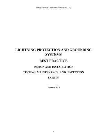
Dependence of Modern Society on Electric Supply1.1The modem society has come to depend heavily upon continuous and reliable availabilityof electricity-and a high quality of electricity too. Computer and telecomm icationnetworks, railway networks, banking and post office networks, continuo&s rocessindustries and life support systems are just a few applications that just cannot functionwithout a highly reliable source of electric power. And add to this, the mind-bogglingnumber of domestic users of electricity whose life is thrown out of gear, in case theelectric supply is disrupted. Thus, the importance of maintaining continuous supply ofelectricity round the clock cannot be overemphasized.No power system can be designed in such a way that it would never fail. So, one hasto live with the failures. In the language of protection engineers, these failures are calledfaults. There is no negative connotation to the word fault in this context. What is moreimportant is, how to prevent the faults and how to e t h consequenceseof the- - ill effects of faults-"are-.minimized. . ---. .faults. Theby.-q",ck!y.isolating the-. faulty. ,. . element. . from .the rest of the healthy systqm; th%.limiting the disturbance,.footprint to as .small an qeea- -1.21.2.1i,- -Faults and Abnormal Operating ConditionsShunt Faults (Short Circuits)When the path of the load current is cut short because of breakdown of insulation, wesay that a 'short circuit' has occurred. The insulation can break down for a variety ofreasons, some of which are listed in Section 1.2.2.Figure 1.1shows a single line-to-groundfault on a transmission line due to flashover of spark gap across the string insulator.Such faults due to insulation flashover are many times temporary, i.e. if the arc pathis allowed to deionize, by interrupting the electrical supply for a sufficient period, thenthe arc does not re-strike after the supply is restored. This p r o f.-is. known .as'ieclosure. In low-voltage systems upfollowed.by intentional re-energization.-. . . ,I-,1yC. ?7 ' 3' : c: .
2F r damentalsof Power Systern Protection--Step-uptransformerArcing fault(L-G fault)'fFigure 1.1 Single line-to-ground fault due to flashover of insulator string.tp thfee.recl re s -ar eattem ted . aRerwhich t h b r e. a.- -.k e ris, locked out. The repeatedattempts at reclosure, a t times, help in burning out the object which is causing thebreakdown of insulation. The reclosure may also be done automatically In EHV systems,,,,- .
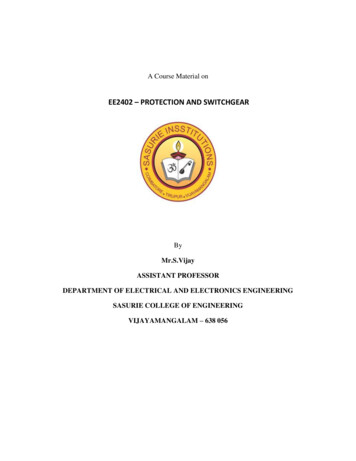
where the damage due to short circuit may be very large and the system stability at stake,only one reclosure is allowed.At times the short circuit may be total (sometimes called a dead short circuit), or itmay be a partial short circuit. A fault which bypasses the entire load current throughitself, is called a metallic fault. A metallic fault presents a very low, practically zero, faultresistance. A partial short circuit can be modelled as a non-zero resistance (or impedance)in parallel with the intended path of the current. Most of the times, the fault resistanceis nothing but the resistance of the arc that is formed as a result of the flashover. Thearc resistance is highly nonlinear in nature. Early researchers have developed models ofthe arc resistance. One such widely used model is due to Warrington, which gives the arcresistance as:awhereS isu ist isI isthethethethespacing in feetvelocity of air in mphtime in secondsfault current in amperes.S u &.f&s e.basicall , due to fajl.u.reof insulation. The insulation may fail becauseof its own weakening, or it may fail due to overvoltage. The weakening of insulation maybe due to one or more of the following factors:-AgeingTemperatureRain, hail, snowChemical pollutionForeign objectsOther causes'i" .;.'The overvoltage may be either internal (due to switching) or external (due to lightening).1.2.3Effects of Shunt FaultsIf the power system just consisted of isolated alternators feeding their own loads, then thesteady-state fault currents would not be q p c h of a concern. Consider a n isolatedturboalternator with a three-phase short circuit on its terminals as shown in Figure 1.2.Assuming the internal voltage to be 1 p.u. and a value of synchronous impedance,Xd 2 p.u., the steady-state short-circuit current would only be 0.5 p.u. which is toosmall to cause any worry. However considering subtransient impedance, X: 0.1, thesubtransient current would be 10 p.u. We must not, however, forget that i n an
(b) Three-phase fault(a) Isolated generator with its load-(c) Subtransient(d)Transient(e) Steady stateFigure 1.2 Isolated generator experiences a three-phase fault.1"interconnected power system all the generators (and even motors) will contribute towardsthe fault current, thus building u p the value of the fault current t o couple of tens of timesthe normal full-load current.Faults, thus, cause heavy currents to flow. If these fault currents persist even fora short time, they will cause extensive damage to the equipment that carry thesecurrents. Over-currents, in general, cause overheating and attendant danger of fire.Overheating also causes deterioration of the insulation, thus weakening it further. Not SOapparent is the mechanical damage due to excessive mechanlcal forces developed duringover-current. Transformers are known to have suffered rnechanlcal damage to theirwindings, due to faults. This is due to the fact that any two current-carrying conductorsexperience a force. This force goes out of bounds during faults, causing mechanicaldistortion and damage.Further, in an interconnected system, there is another dimension to the effect offaults. The generators in an interconnected power system must operate in synchronisma t all instants. The electrical power output from an alternator near the fault dropssharply. However the mechanical power input remains substantially constant a t its prefault value. This causes the alternator to accelerate. The rotor angle 6 starts increasing.Thus, the alternators start swinging with respect to each other. If the swing goes out ofcontrol, the alternators will have to be tripped out. Thus, in an interconnected powersystem, the system stability is a t stake. Therefore, the faults need to be isolated asselectively and as speedily as possiblea
Introduction 51.3Clussificafi nof Shunf Fslulfs1.3.1Phase Faults and Ground FaultsThose faults, which involve only one of the phase conductors and ground, are calledground faults. Faults involving two or more phase conductors, with or without ground,are called phase faults.Power systems have been in operation for over a hundred years now. Accumulatedexperience shows that all faults are not equally likely. Single line to ground faults (L-G)are the most likely whereas the fault due to simultaneous short circuit between all thethree lines, known as the three-phase fault (L-L-L), is the least likely. This is depictedin Table 1.1Table 1.1 Fault statistics with reference to type of faultFaultProbability of occurrence (%)L-GL-LL-L-GL-L-LTotal85%8%5%2%100%SeverityLeast severeMost severeFurther, the probability of faults on different elements of the power system aredifferent. The transmission lines which are exposed to the vagaries of the atmosphere arethe most likely to be subjected to faults. Indoor equipment is least likely to be subjectedto faults. The fault statistics is shown in Table 1.2.Table 1.2 Fault statistics with reference to power system elementsPower system elementOverhead linesUnderground cablesTransformersGeneratorsSwitchgemCT, PT relays, control equipment, etcTotalProbabiliw of faults (9%)5091071212100%The severity of the fault can be expressed in terms of the magnitude of the faultcurrent and hence its potential for causing damage. In the power system, the three-phasefault is the most severe whereas the single line-to-ground fault is the least severe.1.3.2 Phasor Diagram of Voltages and Currents During Various FaultsA fault is accompanied by a build-up of current, which is obvious. At the same time there
of Power Systen Protectio l6 Fu da ,rentaLsis a fall in voltage throughout the power system. If the fault is a metallic fault, the voltageat the fault location is zero. The voltage at the terminals of the generator will also drop,though not drastically. If the source is ideal, there will be no drop in voltage at thegenerator terminals. Normally the relay is away from the fault location. Thus, as seenfrom the relay location, a fault is characterized by a build-up of current, and to a certainextent, collapse of voltage.Figure 1.3 depicts various ground faults a s well as phase faults.-a(b) L-L fault(a) L-Gfault( d ) L-L-L fault(c) L-L-G faultaIiIiI,;1!(e) L-L-L-G fault1.3Various ground faults and phase faults.- .-., , ,,, . ,.
Introduction-7Figure 1.4 depicts a radial power system with a fault near the remote end of thetransmission line. It can be seen from the phasor diagram that the voltage at the relaylocation during fault is less in magnitude than that during the pre-fault condition andalso lags its pre-fault value. In order not to clutter the diagram, only phase a voltage isshown. In Figure 1.5, the distortion in voltages during all the 11 shunt faults areconsidered.IZLI 'blcThree-phase lineThree-phase faultIRelayEa-la Zs ZL'bC -eI, Ebzs ZL-Eczs ZLVa E,-IZ8 SVb Eb - lbZSVc E, - I sFigure 1.4 Fall of voltage at the relay location shown on singleline diagram of a three-phase system.1.3.3Series FaultsSeries faults are nothing but a break in the path of current. Normally such faults do notresult into catastrophes except when the broken conductor touches other conductor or
of Power Svsre,n Protecrio,l8 F mrla nenmls.- -Groundedneutral- - - .- - - - - - - - - -7 - - - L-L fault;T'\A,.Nva--.--.',,.--- -----,,,.- --. .-vc,*,-*-NI-.,- - - - - - - - - - - - V C f l- - - - - . - - - Ia-b fault---:AI-,----------------------A-a-c faultvbA,-- -v,b c faultL-G fault,,;\"aVa\II\vca-g faulta-b-g faultIb-g faulta-c-g faultc-g faultb-c-g faultFigure 1.5 Voltages at the relay location during various faults.Isome grounded part. It is observed in practice that most of the open conductor faultssooner or later develop into some or the other short-circuit fault. However, there are someinstances where an open circuit can have dangerous consequences For example, thesecondary circuit of a current transformer and the field circuit of a dc machine if opencircuited, can have dangerous consequences.
1.4Abnormal Operafjng CondifjonsThe boundary between the normal and faulty conditions is noc crisp. There are certainoperating conditions inherent to the operation of the aower system which are definitelynot normal, but these are not electrical faults either. Some examples are the magnetizinginrush current of a transformer, starting current of an induction motor, and theconditions dunng power swing.1.4.1Should Protective Relays Trip During AbnormalOperating Conditions?How the protective system should respond to the abnormal operating conditions needscareful consideration. It may or may not be required to take c ognizance of the abnormaloperating condition. Some examples of abnormal operating conditions are startingcurrents of motors, inrush currents of transformers and stable power swings. Magnitudewise, these currents may qualify as faults, but there is no need to provide protection from-- w t e c t i v e system-. . .m u s t be able to discriminate between the normalthem. Thus, the--- - .operating. conditions,. . ,,.abnormal operating. condi&io.as,and faults. ,,. .',, 1.4.2 ., , Can Protective Relays Prevent Faults?I t can be seen from the above discussion that protective relays cannot prevent faults. Toa certain extent, faults can be prevented by using the properly designed and maintainedequipment. However, it is not possible to totally prevent the occurrence of faults.1.4.3 What are Protective Relays Supposed to Do?aThe protective relays are supposed to detect the fault with the help of current and voltagetransformers, and selectively remove only the faulty part from the rest of the system bytripping an appropriate number of circuit breakers. This, the relay has to do with utmostsensitivity, selectivity and speed. I n a power system, faults are not an everydayoccurrence. A typical relay, therefore, spends all of its life monitoring the power system.I t must, therefore, be ready all the time in anticipation of a fault. I t is said that a relayoperates far more number of times during testing and maintenance than during actualfault! Thus, relaying is like an insurance against damage due to faults.1.5Evolution of Power Systemsfeeding their own loads to hugePower systems have evolved from isolatedinterconnected power systems spanning an entire country. The evolution has progressedfrom low-voltage systems to high-voltage systems and low-power handling capacities tohigh-power handling capncities. The requirements imposed on the protective system areclosely linked to the nature of the power system.
1.5.1Isolated Power SystemThe protection of an isolated power system is simpler because firstly, there is noconcentration of generating capacity and secondly, a single synchronous alternator doesnot suffer from the stability problem as faced by a multi-machine system. Further, whenthere is a fault and the protective relays remove the generator from the system, thesystem may suffer from a blackout unless there is a standby source of power. As shownin Section 1.2.3, the steady-state fault current in a single machine power system may evenbe less than the full-load current. Such a fault will, however, cause other effects likespeeding up of the generator because of the disturbed balance between the inputmechanical power and the output electrical power, and therefore should be quicklyattended to. Although, there are no longer any isolated power systems supplyingresidential or industrial loads, we do encounter such situations in case of emergencydiesel generators powering the uninterrupted power supplies as well as critical auxiliariesin a thermal or nuclear power station.1.5.2lnterconnected Power SystemAn interconnected power system has evolved because it is more reliable than an isolatedpower system In case of disruption in one part of the system, power can be fed fromalternate paths, thus, maintaining continuity of service. An in
1 7 5 Organization of Protection 17 1.7 6 Zones of Protection 19 1 7.7 Primary and Back-up Protection 20 1.7.8 Maloperations 22 1.8 Various Power System Elements That Need Protection 23 1.9 Various Principles of Power System Protection 23 Reuiew Questions 24 Problems 25 2 OVER-CURRENT PROTECTION OF TRANSMISSION LINES 26-56