Transcription
A Course Material onEE2402– PROTECTION AND SWITCHGEARByMr.S.VijayASSISTANT PROFESSORDEPARTMENT OF ELECTRICAL AND ELECTRONICS ENGINEERINGSASURIE COLLEGE OF ENGINEERINGVIJAYAMANGALAM – 638 056
QUALITY CERTIFICATEThis is to certify that the e-course materialSubject Code :SubjectClassEE- 2402: PROTECTION AND SWITCHGEAR: IV Year EEEBeing prepared by me and it meets the knowledge requirement of the university curriculum.Signature of the AuthorName:Designation:This is to certify that the course material being prepared by Mr.S.Vijay is of adequate quality.He has referred more than five books among them minimum one is from abroad author.Signature of HDName:SEAL
QUALITY CERTIFICATEThis is to certify that the e-course materialSubject Code :SubjectClassEE- 2402: PROTECTION AND SWITCHGEAR: IV Year EEEBeing prepared by me and it meets the knowledge requirement of the university curriculum.Signature of the AuthorName:Designation:This is to certify that the course material being prepared by Mr.S.Vijay is of adequate quality.He has referred more than five books among them minimum one is from abroad author.Signature of HDName:SEAL
EE2402PROTECTION AND SWITCHGEARLTPC3003UNIT IINTRODUCTION9Importance of protective schemes for electrical apparatus and power system. Qualitative reviewof faults and fault currents - relay terminology – definitions - and essential qualities ofprotection. Protection against over voltages due to lightning and switching - arcing grounds Peterson Coil - ground wires - surge absorber and diverters Power System earthing – neutralEarthing - basic ideas of insulation coordination.UNIT IIOPERATING PRINCIPLES AND RELAY CHARACTERISTICS9Electromagnetic relays – over current, directional and non-directional, distance, negativesequence, differential and under frequency rela ys – Introduction to static relays.UNIT IIIAPPARATUS PROTECTION9Main considerations in apparatus protection - transformer, generator and motor protection protection of busbars. Transmission line protection - zones of protection. CTs and PTs and theirapplications in protection schemes.UNIT IVTHEORY OF CIRCUIT INTERRUPTION9Physics of arc phenomena and arc interruption. DC and AC circuit breaking - restriking voltageand recovery voltage - rate of rise of recovery voltage - resistance switching - current chopping interruption of capacitive current.UNIT VCIRCUIT BREAKERS9Types of circuit breakers – air blast, air break, oil, SF6 and vacuum circuit breakers –comparative merits of different circuit breakersbreak ers – testing of circuit breakers.TOTAL : 45 PERIODSTEXT BOOKS:1. M.L. Soni, P.V. Gupta, V.S. Bhatnagar, A. Chakrabarti, ‘A Text Book on Power SystemEngineering’, Dhanpat Rai & Co., 1998. (For All Chapters 1, 2, 3, 4 and 5).2. R.K.Rajput, A Tex book of PowerP ower System Engineering. Laxmi Publications, FirstEdition Reprint 2007.REFERENCES:1. Sunil S. Rao, ‘Switchgear and Protection’, Khanna publishers, New Delhi, 1986.2. C.L. Wadhwa, ‘Electrical Power Systems’,S ystems’, Newage International (P) Ltd., 2000.3. B. Ravindranath, and N. Chander, ‘Power System Protection & Switchgear’, Wiley EasternLtd., 1977.4. Badri Ram, Vishwakarma, ‘Power System Protection and Switchgear’, Tata McGraw Hill,2001.
CONTENTSS.NOTOPICUNIT I INTRODUCTIONPAGE NO.11.1Fundamentals of Power System Protection11.2Consequences of occurrence of Faults21.3Zones and types of Protection system31.4Protection System Requirements and some basic terminologies used41.5Protection against over voltages due to lightning and switching61.6Arcing Grounds91.7surge absorber91.8surge diverter111.9neutral earthing13UNIT II OPERATING PRINCIPLES AND RELAY CHARACTERISTICS292.1Electromagnetic Relay222.2Over Current Relay Working Principle Types262.3Directional Over Current Relays282.4Distance relay282.5Impedance Relay292.6Differential Relay302.7Static relays33UNIT III APPARATUS PROTECTION343.1Over current and earth fault protection343.2Transformer Protection393.3Generator protection463.4Protection of bus bars503.5Zones and types of Protection system523.6CTs and PTs and their applications in protection schemes53UNIT IV THEORY OF CIRCUIT INTERRUPTION564.1Formation of arc during circuit breaking564.2AC and DC circuit breaking594.3Restriking voltage and recovery voltage604.4Rate of rise of recovery voltage614.5Resistance switching624.6Current chopping64UNIT V CIRCUIT BREAKERS675.1Rating of Circuit Breaker675.2Air blast circuit breaker70
5.3Oil circuit breakers735.4SF6 circuit breaker765.5Vacuum circuit breakers785.6Testing of circuit breakers80Question bank82
EE2402PROTECTION & SWITCHGEARUNIT IINTRODUCTION1. Importance of protective schemes for electrical apparatus and power system1.1 Fundamentals of Power System ProtectionThe purpose of an Electric Power System is to generate and supply electrical energy toconsumers. The power system should be designed and managed to deliver this energy to theutilization points with both reliability and economically The capital investment involved inpower system for the generation, transmission and distribution is so great that the properprecautions must be taken to ensure that the equipment not only operates as nearly aspossible to peak efficiency, but also must be protected from accidents The normal path of theelectric current is from the power source through copper (or aluminium) conductors ingenerators, transformers and transmission lines to the load and it is confined to this path byinsulation. The insulation, however, may break down, either by the effect of temperature andage or by a physical accident, so that the current then follows an abnormal path generallyknown as Short Circuit or Fault Any abnormal operating state of a power system is known as FAULT. Faults in general consistof short circuits as well as open circuits. Open circuit faults are less frequent than short circuitfaults, and often they are transformed in to short circuits by subsequent events.1SCEEEE
EE2402PROTECTION & SWITCHGEAR1.2 Consequences of occurrence of FaultsFaults are of two type Short circuit fault- current Open circuit fault- voltageIn terms of seriousness of consequences of a fault , short circuits are of far greater concern thanopen circuits, although some open circuits present some potential hazards to personnelClassification of short circuited Faults Three phase faults (with or without earth connection) Two phase faults (with or without earth connection) Single phase to earth faultsClassification of Open Circuit Faults Single Phase open Circuit Two phase open circuit Three phase open circuitConsequences Damage to the equipment due to abnormally large and unbalanced currents and low voltagesproduced by the short circuits Explosions may occur in the equipments which have insulating oil, particularly during shortcircuits. This may result in fire and hazardous con ditions to personnel and equipments Individual generators with reduced voltage in a power station or a group of generatorsoperating at low voltage may lead to loss of synchronism, subsequently resulting in islanding. Risk of synchronous motors in large industrial premises falling out of step and tripping out.The general layout of a protection system may be viewed as given in the following figure2SCEEEE
EE2402PROTECTION & SWITCHGEAR1.3 Zones and types of Protection systemZones of Protection system An electric power system is divided into several zones of protection. Each zone of protection,contains one or more components of a power system in addition to two circuit breakers. When a fault occurs within the boundary of a particular zone, then th e protection systemresponsible for the protection of the zone acts to isolate (by tripping the Circuit Breakers) everyequipment within that zone from the rest of the system. The circuit Breakers are inserted between the component of the zone and the rest of the powersystem. Thus, the location of the circuit breaker helps to define the boundaries of the zones ofprotection. Different neighbouring zones of protection are made to overlap each other, which ensurethat no part of the power system remains without protection. However, occurrence of thefault with in the overlapped region will initiate a tripping sequence of different circuitbreakers so that the minimum necessary to disconnect the faulty element3SCEEEE
EE2402PROTECTION & SWITCHGEARTypes of Protection (Primary and Back-up Protection)Primary ProtectionThe primary protection scheme ensures fast and selective clearing of any fault within theboundaries of the circuit element, that the zone is required to protect. Primary Protection as a ruleis provided for each section of an electrical installation.However, the primary protection may fail. The primary cause of failure of the Primary Protectionsystem are enumerated below.1. Current or voltage supply to the relay.2. D.C. tripping voltage supply3. Protective relays4. Tripping circuit5. Circuit BreakerBack-up ProtectionBack-up protection is the name given to a protection which backs the primary protectionwhenever the later fails in operation. The back-up protection by definition is slower than theprimary protection system. The design of the back-up protection needs to be coordinated with thedesign of the primary protection and essentially it is the second line of defence after the primaryprotection system.1.4 Protection System Requirements and some basic terminologies used The fundamental requirements for a protection system are as follows:4SCEEEE
EE2402PROTECTION & SWITCHGEARReliability:It is the ability of the protection system to operate correctly. The reliability feature has twobasic elements, which are dependability and security. The dependability feature demands thecertainty of a correct operation of the designed system, on occurrence of any fault. Similarly, thesecurity feature can be defined as the ability of the designed system to avoid incorrect operationduring faults. A comprehensive statisticalmethod based reliability study is required before the protection system may be commissioned. Thefactors which affect this feature of any protection system depends on some of the following fewfactors. Quality of Component used Maintenance schedule The supply and availability of spare parts and stocks The design principle Electrical and mechanical stress to which the protected part of the system is subjected to.Speed:Minimum operating time to clear a fault in order to avoid damage to equipment. The speed ofthe protection system consists primarily of two time intervals of interest.The Relay Time :This is the time between the instant of occurrence of the fault to the instant at which the r elaycontacts open.The Breaker Time:This is the time between the instant of closing of relay contacts to the instant of final arc extinctioninside the medium and removal of the fault.Selectivity:This feature aims at maintaining the continuity of supply system by disconnecting the minimumsection of the network necessary to isolate the fault. The property of selective tripping is also knownas “discrimination”. This is the reason for which the enti re system is divided into several protectivezones so that minimum protion of network is isolated with accuracy. Two examples of utilization ofthis feature in a relaying scheme are as followsa) Time graded systemsb) Unit systems5SCEEEE
EE2402PROTECTION & SWITCHGEARSensitivity:The sensitivity of a relay refers to the smallest value of the actuating quantity at which the relayoperates detecting any abnormal condition. In case of an over current relay, mathematically this canbe defined as the ratio between the short circuit fault cu rrent (Is) and the relay operating current (I o).The value of Io , should not be too small or large so that the relay is either too sensitive or slow inresponding.Stability:It is the quality of any protection system to remain stable within a set of defined operating scenariosand procedures. For example the biased differential scheme of differential protection is more stabletowards switching transients compared to the more simple and basic Merz Price scheme indifferential protectionAdequacy:It is economically unviable to have a 100% protection of the entire system in concern. Therefore, thecost of the designed protection system varies with the criticality and importance of the protectedzone. The protection system for more critical portionsis generally costly, as all the features of a good protection system is maximized here. But asmall motor can be protected by a simple thermally operated relay, which is simple and cheap.Therefore, the cost of the protection system should be adequate in its cost. 1.4.7 Some basicterminologies used in protection system Some basic terminologies commonly used in the protectionsystem are enlisted below. i) Measuring Relay ii) Fault Clearing Time iii) Auxilliary relay iv) RelayTime v) Pick up value vi) Reset Value vii) Drop out viii) Reach ( under and over reaches) ix) RelayBurden x) Unit/ Non unit protection xi) All or Nothing relay1.5 Protection against over voltages due to lightning and switchingOvervoltage ProtectionUnder Electrical ProtectionThere are always a chance of suffering an electrical power system from abnormal overvoltages. These abnormal over voltages may be caused due to various reason such as, suddeninterruption of heavy load, lightening impulses, switching impulses etc. These over voltagestresses may damage insulation of various equipments and insulators of the power system.Although, all the over voltage stresses are not strong enough to damage insulation of system, butstill these over voltages also to be avoided to ensure the smooth operation of electrical powersystem.6SCEEEE
EE2402PROTECTION & SWITCHGEARVoltage SurgeThe over voltage stresses applied upon the power system, are generally transient innature. Transient voltage or voltage surge is defined as sudden sizing of voltage to a high peak invery short duration. The voltage surges are transient in nature, that means they exist for veryshort duration. The main cause of these voltage surges in power system are due to lightningimpulses and switching impulses of the system. But over voltage in the power system may alsobe caused by, insulation failure, arcing ground and resonance etc.The voltage surges appear in the electrical power system due to switching surge, insulationfailure, arcing ground and resonance are not very large in magnitude. These over voltages hardlycross the twice of the normal voltage level. Generally, proper insulation to the differentequipment of power system is sufficient to prevent any damage due to these over voltages. Butover voltages occur in the power system due to lightning is very high. If over voltage protectionis not provided to the power system, there may be high chance of severe damage. Hence all overvoltage protection devices used in power system mainly due to lightning surges.Let us discuss different causes of over voltages one by one.Switching Impulse or Switching SurgeWhen a no load transmission line is suddenly switched on, the voltage on the linebecomes twice of normal system voltage. This voltage is transient in nature. When a loaded lineis suddenly switched off or interrupted, voltage across the line also becomes high enough currentchopping in the system mainly during opening operation of air blast circuit breaker, causes overvoltage in the system. During insulation failure, a live conductor is suddenly earthed. This mayalso caused sudden over voltage in the system. If emf wave produced by alternator is distorted,thththe trouble of resonance may occur due to 5 or higher harmonics. Actually for frequencies of 5or higher harmonics, a critical situation in the system so appears, that inductive reactance of thesystem becomes just equal to capacitive reactance of the system. As these both reactance canceleach other the system becomes purely resistive. This phenomenon is called resonance and atresonance the system voltage may be increased enough.But all these above mentioned reasons create over voltages in the system which are not very highin magnitude.But over voltage surges appear in the system due to lightning impulses are very high inamplitude and highly destructive. The affect of lightning impulse hence must be avoided for overvoltage protection of power system.Methods of Protection Against LightningThese are mainly three main methods generally used for protection against lightning. The y are1. Earthing screen .2. Overhead earth wire .7SCEEEE
EE2402PROTECTION & SWITCHGEAR3. Lighning arrester or surge dividers .Earthing ScreenEarthing screen is generally used over electrical sub-station. In this arrangement a net ofGI wire is mounted over the sub-station. The GI wires, used for earthing screen are properlygrounded through different sub-station structures. This network of grounded GI wire overelectrical sub-station, provides very low resistance path to the ground for lightning strokes.This method of high voltage protection is very simple and economic but the main drawback is, itcan not protect the system from travelling wave which may reach to the sub-station via differentfeeders.Overhead Earth WireThis method of over voltage protection is similar as earthing screen. The only differenceis, an earthing screen is placed over an electrical sub-station, whereas, overhead earthwire isplaced over electrical transmission network. One or two stranded GI wires of suitable crosssection are placed over the transmission conductors. These GI wires are properly grounded ateach transmission tower. These overhead ground wires or earthwire divert all the lightningstrokes to the ground instead of allowing them to strike directly on the transmission conductors.Lightning ArresterThe previously discussed two methods, i.e. earthing screen and over-head earth wire arevery suitable for protecting an electrical power system from directed lightning strokes but systemfrom directed lightning strokes but these methods can not provide any protection against highvoltage travelling wave which may propagate through the line to the equipment of the substation.The lightning arrester is a devices which provides very low impedance path to the groundfor high voltage travelling waves.The concept of a lightning arrester is very simple. This device behaves like a nonlinear electricalresistance. The resistance decreases as voltage increases and vice-versa, after a certain level ofvoltage.The functions of a lightning arrester or surge dividers can be listed as below.1. Under normal voltage level, these devices withstand easily the system voltage as electricalinsulator and provide no conducting path to the system current.2. On occurrence of voltage surge in the system, these devices provide very low impedancepath for the excess charge of the surge to the ground.3. After conducting the charges of surge, to the ground, the voltage becomes to its normallevel. Then lightning arrester regains its insulation properly and prevents regains itsinsulation property and prevents further conduction of current, to the ground.8SCEEEE
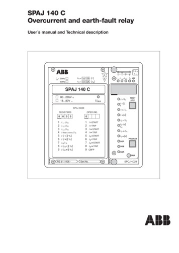
EE2402PROTECTION & SWITCHGEARThere are different types of lightning arresters used in power system, such as rod gap arrester,horn gap arrester, multi-gap arrester, expulsion type LA, value type LA.In addition to these the most commonly used lightning arrester for over voltage protection nowa-days gapless ZnO lightning arrester is also used.1.6 Arcing GroundsArcing Grounds is a phenomenon which is observed in ungrounded three phasesystems. In ungrounded three phase systems operating in a healthy balanced conditions,capacitances are formed between the conductors and ground. The voltage across thesecapacitances is the phase voltage.Now, in the event of a ground fault, the voltage across the faulty conductor becomes zerowhile the voltages across the healthy conductors increase by a factor of 1.732.The arc caused between the faulty conductor and the ground gets extinguished and restarts manytimes, this repeated initiation and extinction of the arc across the fault produces severe voltageoscillations of the order of nearly three to four times the nominal voltage.This repeated arcing across the fault due to the capacitances between the conductors and theground is known as arcing grounds. Arcing grounds can be eliminated by the use of PetersonCoils (see Article) and Arc Suppression Coils1.7 surge absorberSurge absorbers are protective devices used to absorb the complete surge i,e. due tolightening surge or any transient surge in the system unlike the lightening arrestor in which anon-linear resistor is provided which provides a low resistance path to the dangerously highvoltages on the system to the earth.Ferranti surge absorber Surge absorber is of following types:Ferranti surge absorber: Ferranti surge absorber consists of an air core inductor which isconnected in series with the line and surrounded by an earth metallic sheet. The earth metallic9SCEEEE
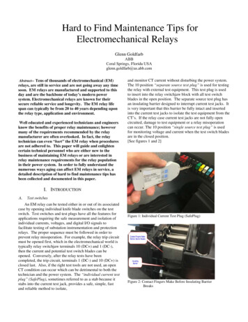
EE2402PROTECTION & SWITCHGEARsheet is known as dissipater, The dissipater is insulated from the inductor by the air as shown inFigure. This surge absorber acts like an air-cored transformer whose primary is the lowinductance inductor and the dissipater as the single-turn short circuit secondary. Whenever atravelling wave is incident on the surge absorber, energy is transformed by mutual inductancebetween the coil and dissipatcr. Because of the series inductance the steepness of the wave isalso reduced.ERA surge absorber:An improved form of the surge absorber is the Electrical Research Association (ERA)type surge Filter as shown in Figure incorporated a gap G and expulsion gap E. When a wavereaches the inductor L, a high voltage is induced across it causing the gap G to break downputting the resistor R and expulsion gap E into circuit. An incoming wave is thus flattened by theinductor and the resistor and its amplitude is reduced b y the expulsion gap.10SCEEEE
EE2402PROTECTION & SWITCHGEAR1.8 surge diverterA surge arrester is a device to protect electrical equipment from over-voltage transientscaused by external (lightning) or internal (switching) events. Also called a surge protectiondevice (SPD) ortransient voltage surge suppressor (TVSS), this class of device is used toprotect equipment in power transmission and distribution systems. (For consumer equipmentprotection, different products called surge protectors are used.)To protect a unit of equipment from transients occurring on an attached conductor, a surgearrester is connected to the conductor just before it enters the equipment. The surge arrester isalso connected toground and functions by routing energy from an over-voltage transient toground if one occurs, while isolating the conductor from ground at normal operating voltages.This is usually achieved through use of a varistor, which has substantially different resistances atdifferent voltages.Surge arresters are not generally designed to protect against a direct lightning strike to aconductor, but rather against electrical transients resulting from lightning strikes occurring in thevicinity of the conductor. Lightning which strikes the earth results in ground currents which canpass over buried conductors and induce a transient that propagates outward towards the ends ofthe conductor. The same kind of induction happens in overhead and above ground conductorswhich experience the passing energy of an atmospheric EMP caused by the lightening flash.Surge arresters only protect against induced transients characteristic of a lightning discharge'srapid rise-time and will not protect against electrification caused by a direct strike to theconductor. Transients similar to lightning-induced, such as from a high voltage system's faultswitching, may also be safely diverted to ground; however, continuous overcurrents are notprotected against by these devices. The energy in a handled transient is substantially less thanthat of a lightning discharge; however it is still of sufficient quantity to cause equipment damageand often requires protection.Without very thick insulation, which is generally cost prohibitive, most conductorsrunning more than a minimal distance, say greater than about 50 feet, will experience lightninginduced transients at some time during use. Because the transient is usually initiated at somepoint between the two ends of the conductor, most applications install a surge arrester just beforethe conductor lands in each piece of equipment to be protected. Each conductor must beprotected, as each will have its own transient induced, and each SPD must provide a pathway toearth to safely divert the transient away from the protected component. The one notableexception where they are not installed at both ends is in high voltage distribution systems. Ingeneral, the induced voltage is not sufficient to do damage at the electric generation end of thelines; however, installation at the service entrance to a building is key to protecting downstreamproducts that are not as robust.11SCEEEE
EE2402PROTECTION & SWITCHGEARSurge Diverters operationThe event we commonly call a surge is more accurately defined as a high voltagetransient or impulse. Surge diverters are designed to divert the impulse away from the sensitiveelectronic system. That’s why the term diverter is more appropriate – it better describes thefunction of this device. Surge diverter products commonly use one or more of several electroniccomponents. These include metal oxide varistors (MOVs), silicon avalanche diodes (SADs), andgas tubes. There are differences in how each functions but the intent is the same divert a part ofthe harmful impulse energy away from the computer or system being protected.All surge diverters have a voltage threshold, called a “clamping voltage”, at which theybegan to conduct. Above that threshold, impulses are shunted across the diverter to anotherpathway. When the impulse voltage once again falls below the threshold, the diverter stopsconducting. Surge diverters also have a “clamping response” time or the time required for thedevice to respond to an impulse. The amount of energy each is capable of handling without beingdestroyed is also a consideration. Due to these factors, each type of component used in surgediverters has unique advantages and disadvantages. MOVs have a high clamping voltage (300 to500 volts) and a slow response time.This means that in best case scenarios, voltage impulses of less than 500 volts usuallyenter the computer system unimpeded. In addition, higher voltage events with very fast rise timesmay pass by the MOV before it is able to respond. And while MOVs can handle a significantamount of energy, they are physically degraded each time they clamp. This characteristic alterstheir future performance and ultimately leads to physical failure.These disadvantages have led to the use of the silicon avalanche diode (SAD) either inconjunction with the MOV or in standalone applications. Compared to MOVs, SADs have afaster response time and are not subject to the physical degradation that characterizes MOVsdesign. The overall energy handling ability of the SAD, however, is not as high, and an impulsethat merely degrades and MOV may cause outright destruction of the SAD. To overcome thisdisadvantage, many surge diverter manufacturers whose designs use standalone SADs willparallel multiple SADs to increase the overall energy handling capability of the protector.12SCEEEE
EE2402PROTECTION & SWITCHGEARIndustry authorities often vigorously debate the effectiveness of this design method. Gas tubesare comparatively slow and have a high clamp voltage. However, they handle almost unlimitedamounts of energy. Some surge diverter designs have employed gas tubes as the final line of“brute force” protection to spare the lives of the other surge diverter components in the presenceof a catastrophic powerline disturbance. In fact, many surge diverter designs incorporateparalleled MOVs, SADs, and/or gas tubes in an effort to improve performance b y combining therelative strengths of each particular component1.9 neutral earthingTypes of Neutral Earthing in Power Distribution: Introduction :In the early power systems were mainly Neutral ungrounded due to the fact that the firstground fault did not require the tripping of the system. An unscheduled shutdown on the firstground fault was particularly undesirable for contin uous process industries. These power systemsrequired ground detection systems, but locating the fault often proved difficult. Althoughachieving the initial goal, the ungrounded system provided no control of transient over-voltages.A capacitive coupling exists between the system conductors and ground in a typical distributionsystem. As a result, this series resonant L-C circuit can create over-voltages well in excess ofline-to-line voltage when subjected to repetitive re-strikes of one phase to ground. This in turn,reduces insulation life resulting in possible equipment failure. Neutral grounding systems aresimilar to fuses in that they do nothing until something in the system goes wrong. Then, likefuses, they protect personnel and equipment from damage. Damage comes from two factors, howlong the fault lasts and how large the fault current is. Ground relays trip breakers and limit howlong a fault lasts and Neutral grounding resistors limit how large the fault c urrent is.Importance of Neutral Grounding:There are many neutral grounding options available for both Low and Medium voltagepower systems. The neutral points of transformers, generators and rotating machinery to theearth ground network provides a reference point of zero volts. This protective measure offersmany advantages over an ungrounded system, like, Reduced magnitude of transient over voltages Simplified ground fault location Improved system and equipment fault protection Reduced maintenance time and expense Greater safety for personne
EE2402 PROTECTION & SWITCHGEAR 4 SCE EEE Types of Protection (Primary and Back-up Protection) Primary Protection The primary protection scheme ensures fast and selective clearing of any fault within the boundaries of the circuit element, that the