Transcription
UNIT - IPower System Protection and Switchgear – SEE1401UNIT 1- INTRODUCTION1
I.IntroductionEssential requirements of protection - nature and causes of faults - types of faults - effectsof faults - zones of protection - protection schemes - CTs and PTs and their applications Basic relay terminology.1.1NEED FOR PROTECTIVE SYSTEMSAn electrical power system consists of generators, transformers, transmission anddistribution lines, etc. Short circuits and other abnormal conditions often occur on a powersystem. The heavy current associated with short circuits is likely to cause dam- age toequipment if suitable protective relays and circuit breakers are not provided for theprotection of each section of the power system. Short circuits are usually called faults bypower engineers. Strictly speaking, the term ‗fault‘ simply means a ‗defect‘. Some defects,other than short circuits, are also termed as faults. For example, the failure of conductingpath due to a break in a conductor is a type of fault.If a fault occurs in an element of a power system, an automatic protective device is neededto isolate the faulty element as quickly as possible to keep the healthy sec- tion of thesystem in normal operation. The fault must be cleared within a fraction of a second. If ashort circuit persists on a system for a longer, it may cause damage to some importantsections of the system. A heavy short circuit current may cause a fire. It may spread in thesystem and damage a part of it. The system voltage may reduce to a low level andindividual generators in a power station or groups of generators in different power stationsmay lose synchronism. Thus, an uncleared heavy short circuit may cause the total failure ofthe system.A protective system includes circuit breakers, transducers (CTs and VTs), and protectiverelays to isolate the faulty section of the power system from the healthy sections. A circuitbreaker can disconnect the faulty element of the system when it is called upon to do so bythe protective relay. Transducers (CTs and VTs) are used to reduce currents and voltagesto lower values and to isolate protective relays from the high voltages of the power system.The function of a protective relay is to detect and locate a fault and issue a command to thecircuit breaker to disconnect the faulty element. It is a device which senses abnormalconditions on a power system by con- stantly monitoring electrical quantities of thesystems, which differ under normal and abnormal conditions. The basic electricalquantities which are likely to change dur- ing abnormal conditions are current, voltage,phase-angle (direction) and frequency. Protective relays utilise one or more of thesequantities to detect abnormal conditions on a power system.Protection is needed not only against short circuits but also against any other abnormalconditions which may arise on a power system. A few examples of other abnormalconditions are overspeed of generators and motors, overvoltage, under-2
frequency, loss of excitation, overheating of stator and rotor of an alternator etc.Protective relays are also provided to detect such abnormal conditions and issue alarmsignals to alert operators or trip circuit breaker.A protective relay does not anticipate or prevent the occurrence of a fault, rather it takesaction only after a fault has occurred. However, one exception to this is the Buchholzrelay, a gas actuated relay, which is used for the protection of power transformers.Sometimes, a slow breakdown of insulation due to a minor arc may take place in atransformer, resulting in the generation of heat and decomposition of the transformer‘s oiland solid insulation. Such a condition produces a gas which is collected in a gas chamberof the Buchholz relay. When a specified amount of gas is accumulated, the Buchholz relayoperates an alarm. This gives an early warning of incipient faults. The transformer is takenout of service for repair before the incipient fault grows into a serious one. Thus, theoccurrence of a major fault is prevented. If the gas evolves rapidly, the Buchholz relaytrips the circuit breaker instantly.The cost of the protective equipment generally works out to be about 5% of the total costof the system.1.2NATURE AND CAUSES OF FAULTSFaults are caused either by insulation failures or by conducting path failures. The failureof insulation results in short circuits which are very harmful as they may damage someequipment of the power system. Most of the faults on transmission and distribution linesare caused by overvoltages due to lightning or switching surges, or by external conductingobjects falling on overhead lines. Overvoltages due to light- ing or switching surges causeflashover on the surface of insulators resulting in short circuits. Sometimes, insulators getpunctured or break. Sometimes, certain foreign particles, such as fine cement dust or sootin industrial areas or salt in coastal areas or any dirt in general accumulates on the surfaceof string and pin insulators. This reduces their insulation strength and causes flashovers.Short circuits are also caused by tree branches or other conducting objects falling on theoverhead lines.Birds also may cause faults on overhead lines if their bodies touch one of the phases andthe earth wire (or the metallic supporting structure which is at earth potential). If theconductors are broken, there is a failure of the conducting path and the conductor becomesopen-circuited. If the broken conductor falls to the ground, it results in a short circuit.Joint failures on cables or overhead lines are also a cause of failure of the conducting path.The opening of one or two of the three phases makes the system unbalanced. Unbalancedcurrents flowing in rotating machines set up harmonics, thereby heating the machines inshort periods of time. Therefore, unbalancing of the lines is not allowed in the normaloperation of a power system. Other causes of faults on overhead lines are: direct lightningstrokes, aircraft, snakes, ice and snow loading, abnormal loading, storms, earthquakes,creepers, etc. In the case of cables, transformers, generators and other equipment, thecauses of faults are: failure of the solid insulation due to aging, heat, moisture orovervoltage, mechanical damage, accidental contact with earth or earthed screens,flashover due to overvolt- ages, etc.3
1.3TYPES OF FAULTSTwo broad classifications of faults are(i)Symmetrical faults(ii)Unsymmetrical faultsSymmetrical FaultsA three-phase (3-f) fault is called a symmetrical type of fault. In a 3-f fault, allthe three phases are short circuited. There may be two situations—all the threephases may be short circuited to the ground or they may be short-circuitedwithout involving the ground. A 3-f short circuit is generally treated as astandard fault to determine the system fault level.Unsymmetrical FaultsSingle-phase to ground, two-phase to ground, phase-to-phase short circuits;single- phase open circuit and two-phase open circuit are unsymmetrical typesof faults.Single-phase to Ground (L-G) FaultA short circuit between any one of the phase conductors and earth is called asin- gle phase to ground fault. It may be due to the failure of the insulationbetween a phase conductor and the earth, or due to phase conductor breakingand falling to the ground.Two-phase to Ground (2L-G) FaultA short circuit between any two phases and the earth is called a double line toground or a two-phase to ground fault.Phase-to-Phase (L-L) FaultA short circuit between any two phases is called a line to line or phase-tophase fault.Open-circuited PhasesThis type of fault is caused by a break in the conducting path. Such faultsoccur when one or more phase conductors break or a cable joint or a joint onthe overhead lines fails. Such situations may also arise when circuit breakersor isolators open but fail to close one or more phases. Due to the opening ofone or two phases, unbalanced currents flow in the system, thereby heatingrotating machines. Protective schemes must be provided to deal with suchabnormal situations.4
Winding FaultsAll types of faults discussed above also occur on the alternator, motor and transformer windings. In addition to these types of faults, there is one more type offault, namely the short circuiting of turns which occurs on machine windings.Simultaneous FaultsTwo or more faults occurring simultaneously on a system are known as multiple orsimultaneous faults. In simultaneous faults, the same or different types of faults may occurat the same or different points of the system. An example of two different types of faultsoccurring at the same point is a single line to ground fault on one phase and breaking ofthe conductor of another phase, both simultaneously present at the same point. Thesimultaneous presence of an L-G fault at one point and a second L-G fault on anotherphase at some other point is an example of two faults of the same type at two differentpoints. If these two L-G faults are on the same section of the line, they are treated as adouble line to ground fault. If they occur in different line sections, it is known as a crosscountry earth fault. Cross-country faults are common on sys- tems grounded through highimpedance or Peterson coil but they are rare on solidly grounded systems1.4EFFECTS OF FAULTSThe most dangerous type of fault is a short circuit as it may have the following effects ona power system, if it remains uncleared.(i)Heavy short circuit current may cause damage to equipment or any other elementof the system due to overheating and high mechanical forces set up due to heavy current.(ii)Arcs associated with short circuits may cause fire hazards. Such fires, result- ingfrom arcing, may destroy the faulty element of the system. There is also a possibility ofthe fire spreading to other parts of the system if the fault is not isolated quickly.(iii) There may be reduction in the supply voltage of the healthy feeders, resulting inthe loss of industrial loads.(iv)Short circuits may cause the unbalancing of supply voltages and currents, therebyheating rotating machines.(v)There may be a loss of system stability. Individual generators in a power stationmay lose synchronism, resulting in a complete shutdown of the system. Loss of stabilityof interconnected systems may also result. Subsys- tems may maintain supply for theirindividual zones but load shedding would have to be resorted in the sub-system whichwas receiving power from the other subsystem before the occurrence of the fault.5
(vi)The above faults may cause an interruption of supply to consumers, therebycausing a loss of revenue.High grade, high speed, reliable protective devices are the essential requirements of apower system to minimise the effects of faults and other abnormalities.1.5FAULT STATISTICSFor the design and application of protective scheme, it is very useful to have an idea of thefrequency of occurrence of faults on various elements of power system. Usually the powerstations are situated far away from the load centres, resulting in hundreds of kilometers‘length of overhead lines being exposed to atmospheric conditions. The chances of faultsoccurring due to storms, falling of external objects on the lines, flashovers resulting fromdirt deposits on insulators, etc., are greater for overhead lines than for other parts of thepower system. Table 1.1 gives an approximate idea of the fault statistics.Table 1.1 Percentage Distribution of Faults in Various Elements of a Power SystemElement% of Total FaultsOverhead LinesUnderground CablesTransformersGeneratorsSwitchgearsCTs, VTs, RelaysControl Equipment, etc.5091071212From Table 1.1, it is evident that 50% of the total faults occur on overhead lines. Hence itis overhead lines that require more attention while planning and designing protectiveschemes for a power system.Table 1.2 shows the frequency of occurrence of different types of faults (mainly thedifferent types of short circuits) on overhead lines. From the table it is evident that thefrequency of line to ground faults is more than any other type of fault, and hence theprotection against L-G fault requires greater attention in planning and design of protectiveschemes for overhead lines.Table 1.2 Frequency of Occurrence of Different Types of Faults on Overhead LinesTypes of FaultsFaultSymbolLine to GroundLine to LineDouble Line to GroundThree PhaseL-GL-L2L-G3-f% ofTotalFaults858526
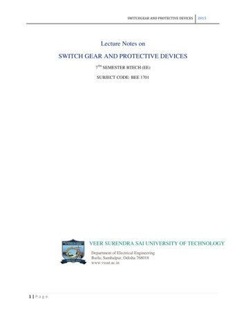
In the case of cables, 50% of the faults occur in cables and 50% at end junctions. Cablefaults are usually of a permanent nature and hence, automatic reclosures are notrecommended for cables.1.6ZONES OF PROTECTIONA power system contains generators, transformers, bus bars, transmission and distribution lines, etc. There is a separate protective scheme for each piece of equipment orelement of the power system, such as generator protection, transformer protection,transmission line protection, bus bar protection, etc. Thus, a power system is divided intoa number of zones for protection. A protective zone covers one or at the most twoelements of a power system. The protective zones are planned in such a way that theentire power system is collectively covered by them, and thus, no part of the system is leftunprotected. The various protective zones of a typical power system are shown in Fig. 1.1.Adjacent protective zones must overlap each other, failing which a fault on the boundaryof the zones may not lie in any of the zones (this may be due to errors in the measurementof actuating quantities, etc.), and hence no circuit breaker would trip. Thus, theoverlapping between the adjacent zones is unavoidable. If a fault occurs in theoverlapping zone in a properly protected scheme, more circuit breakers than the minimumnecessary to isolate the faulty element of the system would trip. A relatively low extent ofoverlap reduces the probability of faults in this region and consequently, tripping of toomany breakers does not occur frequently.Fig. 1.1 Zone of Protection7
1.7PRIMARY AND BACK-UP PROTECTIONIt has already been explained that a power system is divided into various zones forits protection. There is a suitable protective scheme for each zone. If a fault occursin a particular zone, it is the duty of the primary relays of that zone to isolate fense.Ifduetoanyreason,theprimary relay fails to operate, there is a back-up protective scheme to clear thefault as a second line of defence.The causes of failures of protective scheme may be due to the failure of tyoffailuresisshownagainsteachitem.The reliability of protective scheme should at least be 95%. With proper design,installation and maintenance of the relays, circuit breakers, trip mechanisms, acand dc wiring, etc. a very high degree of reliability can be achieved.The back-up relays are made independent of those factors which might ratimedelaytogivetheprimary relaysufficient time to operate. When a back-up relay operates, a larger part of thepower system is disconnected from the power source, but this is unavoidable. Asfar as possible, a back-up relay should be placed at a different station. Sometimes,a local back-up is also used. It should be located in such a way that it doesnotemploy components (VT, CT, measuring unit, etc.) common with the primaryrelays which are to be backed up. There are three types of )Breakerback-upTable 1.3 Percentage failure rate of various equipmentName of Equipment% of Total FailuresRelays44Circuit breaker interrupters14AC wiring12Breaker trip mechanisms8Current transformers7DC wiring5VT3Breaker auxiliary switches3Breaker tripcoils3DC supply18
1.7.1 RemoteBack-upWhen back-up relays are located at a neighbouring station, they back-up the dthesimplest form of back-up protection and is a widely used back-up protection fortransmission lines. It is most desirable because of the fact that it will not fail dueto the factors causing the failure of the primary protection.1.7.2 itionalrelayisprovidedforback-upprotection. It trips the same circuit breaker if the primary relay fails and thisopera- tion takes place without delay. Though such a back-up is costly, it canbe recom- mended where a remote back-up is not possible. For back-up relays,principles of operation that are different from those of the primary protectionas desirable. They should be supplied from separate current and potentialtransformers.1.7.3 BreakerBack-upThis is also a kind of a local back-up. This type of a back-up is necessary for abus bar system where a number of circuit breakers are connected to it. When aprotec- tive relay operates in response to a fault but the circuit breaker fails totrip, the fault is treated as a bus bar fault. In such a situation, it becomesnecessary that all other circuit breakers on that bus bar should trip. After atime-delay, the main relay closes the contact of a back-up relay which trips allother circuit breakers on the bus if the proper breaker does not trip within aspecified time after its trip coil is energised.1.8ESSENTIAL QUALITIES OF PROTECTIONThe basic requirements of a protective system are as follows:(i) Selectivity ordiscrimination(ii) Reliability(iii) Sensitivity(iv) Stability(v) Speed and time(vi) Adequateness(vii) Simplicity and economy1.8.1 Selectivity orDiscriminationSelectivity, is the quality of protective relay by which it is able to discriminatebetween a fault in the protected section and the normal condition. Also, itshould be able to distinguish whether a fault lies within its zone of protection9
or outside the zone. Sometimes, this quality of the relay is also calleddiscrimination. When afault occurs on a power system, only the faulty part etweenafaultandtransientconditions like power surges or inrush of a transformer‘s magnetising current.The magnetising current of a large transformer is comparable to a faultcurrent, which may be 5 to 7 times the full load current. When generators owofheavycurrents is known as a power surge. The protective relay should be able nherentcharacteristicorwiththehelp ofanauxiliary relay. Thus, we see that a protective relay must be able todiscriminate between those conditions for which instantaneous tripping isrequired and those for which no operation or a time-delay operation isrequired.1.8.2 nafaultoccursinitszoneofprotection. Thefailure of a protective system may be due to the failure of any one or more aretheprotectiverelay,circuitbreaker, VT, CT, wiring, battery, etc. To achieve a high degree of reliability,greater attention should be given to the design, installation, maintenance andtesting of the various elements of the protective system. Robustness and liability.Thecontactpressure,thecontactmaterialof therelay, and the prevention of contact contamination are also very important fromthe reliability point of view. A typical value of reliability of a protective scheme is95%.1.8.3 SensitivityA protective relay should operate when the magnitude of the current exceeds thepreset value. This value is called the pick-up current. The relay should not operatewhen the current is below its pick-up value. A relay should be sufficientlysensitive to operate when the operating current just exceeds its pick-up value.1.8.4 enalargecurrentisflowingthrough itsprotective zone due to an external fault, which does not lie in its zone. The concerned circuit breaker is supposed to clear the fault. But the protective system oneinwhichfaulthasoccurred fails10
to operate. After a preset delay the relay will operate to trip the circuitbreaker.1.8.5 Speed and efaultyelementofthesystemasquickly as possible to minimise damage to the equipment and to maintain itycriterionisveryimportant andhence, the operating time of the protective system should not exceed the criti- calclearing time to avoid the loss of synchronism. Other points under considerationfor quick operation are protection of the equipment from burning due to heavyfault currents, interruption of supply to consumers and the fall in system voltagewhich may result in the loss of industrial loads. The operating time of a protectiverelay is usually one cycle. Half-cycle relays are also available. For distributionsystems the operating time may be more than onecycle.1.8.6AdequatenessIt is impossible to provide protection against each and every fault and in each equipment.But the protective system should provide adequate (sufficient) protection for all theelements in the system. The adequateness is assessed by Ratings, cost, Location of theequipments, probability of abnormal condition due to internal and external faults,Discontinuity of the supply due to failure of the equipment1.8.7 Simplicity and EconomyIn addition to all important qualities, it is necessary that the cost of the system should bewell within the limits. As a rule, the protection cost should not be more than 5% of the totalcost. If the equipment to be protected is more important, then Economic considerations arerelaxed. The protective system should be as simple as possible so that it can be easilymaintained. The simpler systems are always more reliable1.9 CLASSIFICATION OF PROTECTIVE SCHEMESA protective scheme is used to protect an equipment or a section of the line. Itincludes one or more relays of the same or different types. The following arethe most common protective schemes which are usually used for theprotection of a modern power rotection11
1.9.1 OvercurrentProtectionThis scheme of protection is used for the protection of distribution lines, largemotors, equipment, etc. It includes one or more overcurrent relays. Anovercurrent relay operates when the current exceeds its pick-up value.1.9.2 DistanceProtectionDistance protection is used for the protection of transmission or subtransmission lines; usually 33 kV, 66 kV and l32 kV lines. It includes anumber of distance relays of the same or different types. A distance relaymeasures the distance between the relay location and the point of fault in termsof impedance, reactance, etc. The relay operates if the point of fault lies withinthe protected section of the line. There are various kinds of distance relays.The important types are impedance, reactance and mho type. An impedancerelay measure the line impedance between the fault point and relay location; areactance relay measures reactance, and a mho relay measures a component ofadmittance.1.9.3 Carrier-CurrentProtectionThis scheme of protection is used for the protection of EHV and UHV lines,gener- ally 132 kV and above. A carrier signal in the range of 50-500 kc/s tistransmittedfrom one end of the line section to the other. Depending on the information,relays placed at each end trip if the fault lies within their protected elaysareofdistancetypeandtheirtrippingoperation is controlled by the carrier signal.1.9.4 DifferentialProtectionThis scheme of protection is used for the protection of generators,transformers, motors of very large size, bus zones, etc. CTs are placed on secondariesareappliedtotherelaycoils. The relay compares the current entering a machine winding and leavingthe same. Under normal conditions or during any external fault, the currententering the wind- ing is equal to the current leaving the winding. But in thecase of an internal fault on the winding, these are not equal. This difference inthe current actuates the relay. Thus, the relay operates for internal faults andremains inoperative under normal conditions or during external faults. In caseof bus zone protection, CTs are placed on the both sides of the busbar.12
1.10BASIC RELAY TERMINOLOGYRelay: A relay is an automatic device by means of which an electrical circuitis indirectly controlled (opened or closed) and is governed by a change in thesame or another electrical circuit.Protective relay: A protective relay is an automatic device which detects anabnor- mal condition in an electrical circuit and causes a circuit breaker toisolate thefaulty element of the system. In some cases it may give an alarm orvisible indication to alertoperator.Operating force or torque: A force or torque which tends to close thecontacts of the relay.Restraining force or torque: A force or torque which opposes theoperatingforce/ torque.Actuating quantity: An electrical quantity (current, voltage, etc) to whichrelay atingquantity(current,voltage,etc.)above which the relayoperates.Reset on drop-out (level): The threshold value of the actuating deenergisedandreturnstoitsnormalposition or state. Consider a situation where umvalueofthecurrentthecontactswillstart opening. This condition is called reset or drop-out. The maximum valueof the actuating quantity below which contacts are opened is called the reset ordrop-out instantatwhichtheactuatingquantity exceeds the relays pick-up value to the instant at which the relaycloses its omenttheactuatingquantityfallsbelow its reset value to the instant when the relay comes back to its normal(initial) position.Setting: The value of the actuating quantity at which the relay is set to operate.Seal-in relay: This is a kind of an auxiliary relay. It is energised by the contacts ofthe main relay. Its contacts are placed in parallel with those of the main relay andis designed to relieve the contacts of the main relay from their current carryingduty.It remains in the circuit until the circuit breaker trips. The seal-in contacts are13
usually heavier than those of the main relay.Back-up relay: A back-up relay operates after a slight delay, if the main relayfails to operate.Back-up protection: The back-up protection is designed to clear the fault if theprimary protection fails. It acts as a second line of tyoftheprimaryprotectiveschemetoclear the fault. It acts as a first line of defence. If it fails, the back-up protectionclears thefault.Auxiliary relays: Auxiliary relays assist protective relays. They repeat the operations of protective relays, control switches, etc. They relieve the protective m,etc.Theymaybeinstantaneousormay have a timedelay.Electromagnetic relay: A relay which operates on the electromagnetic principle,i.e., an electromagnet attracts magnetic moving parts (e.g.,) plunger type movingiron type, attracted armature type). Such a relay operates principally by action ofan electromagnetic element which is energized by the input quantity.Electromechanical relay: An electrical relay in which the designed response isdeveloped by the relative movement of mechanical elements under the action of calmovementofmechanicalparts resulting from electromagnetic or electrothermic forces created by the inputquantities.Static relays: These are solid state relays and employ semiconductor diodes, transistors, thyristors, logic gates, ICs, etc. The measuring circuit is a static circuit relaywhichisadcpotarised relay isused as the trippingdevice.Analog relay: An analog relay is that in which the measured quantities arecon- verted into lower voltage but similar signals, which are then combined orcompared directly to reference values in level detectors to produce the ichthemeasuredacquantitiesaremanipulated in analog form and subsequently converted into either square-wavevoltagesor digital form. Logic circuits or microprocessors compare either thephase relation- ships of the square waves or the magnitudes of the quantities indigital form tomake a trip decision.Numerical relay: A numerical relay is that in which the measured ac quantities are sequentially sampled and converted into numerical (digital) data form.A microprocessor or a microcontroller processes the data numerically (i.e.,performs mathematical and/or logical operations on the data) using analgorithm to calculate the fault discriminants and make tripdecisions.14
Microprocessor-based relay: A microprocessor is used to perform allfunctions of a relay. It measures electrical quantities, makes comparisons,performs computa- tions, and sends tripping signals. It can realise all sorts ofrelaying characteristics, even irregular curves which cannot
Power System Protection and Switchgear – SEE1401 UNIT 1- INTRODUCTION . 2 I. Introduction Essential requirements of protection - nature and causes of faults - types of faults - effects of faults - zones of protection - protection schemes - CTs and PTs and their applications -