Transcription
INDETERMINATETRUCTURAL ANALYSISKenneth Derucher, Chandrasekhar PutchaandUksun KimThe Edwin Mellen PressLewiston Queenston Lampeter
Library of Congress Cataloging-in-Publication DataLibrary of Congress Control Number: 2013934083Derucher, Kenneth.Indeterminate structural analysis / Kenneth Derucher, ChandrasekharPutcha, Uksun Kim.1. Mathematics--advanced. 2. Science--mechanics--dynamics--general. 3.Putcha, Chandrasekhar. 4. Kim, Uksun.p. cm.Includes bibliographical references and index.ISBN-13: 978-0-7734-4470-6 (hardcover)ISBN-10: 0-7734-4470-X (hardcover)I. Title.hors serie.A CIP catalog record for this book is available from the British Library.CopyrightUksun Kim2013 Kenneth Derucher, Chandrasekhar Putcha, andAll rights reserved. For information contactThe Edwin Mellen PressBox 450Lewiston, New YorkUSA 14092-0450The Edwin Mellen PressBox 67Queenston, OntarioCANADA LOS 1 LOThe Edwin Mellen Press, Ltd.Lampeter, Ceredigion, WalesUNITED KINGDOM SA48 8LTPrinted in the United States of America
Tahla of ContentsPREFACEINTRODUCTION1CHAPTER 1- ANALYSIS OF STATICALLYINDETERMINATE STRUCTURES BY THE FORCEMETHOD31.1 Basic Concepts of the Force Method31.1.1 List of Symbols and Abbreviations Used in the Force Method41.2 Static Indeterminacy41.3 Basic Concepts of the Unit Load Method for Deflection Calculation61.4 Maxwell's Theorem of Reciprocal Deflections71.5 Application of Force Method to Analysis of Indeterminate Beams81.5.1 Sign Convention1.5.3 Structures with Several Redundant Forces9161.6 Application of the Force Method to Indeterminate Frames161.7 Application of Force Method to Analysis of Indeterminate Trusses211.8 Summary26Problems27CHAPTER 2 - DISPLACEMENT METHOD OFANALYSIS: SLOPE-DEFLECTION METHOD292.1 Basic Concepts of the Displacement Method292.2 Basic Procedure of the Slope-Deflection Method30302.2.1 Slope-Deflection Equations2.2.2 Sign Convention for Displacement Methods2.2.3 Fixed-End Moments2.3 Analysis of Continuous Beams by the Slope-Deflection Method313232
2.4 Analysis of Continuous Beams with Support Settlements by the SlopeDeflection Method362.5 Application of the Slope-Deflection Method to Analysis of FramesWithout Joint Movement412.6 Derivation of Shear Condition for Frames (With Joint Movement)452.7 Application of the Slope-Deflection Method to Analysis of Frames WithJoint Movement462.8 Summary49ProblemsSOCHAPTER 3 - DISPLACEMENT METHOD OFANALYSIS: MOMENT DISTRIBUTION METHOD533.1 Basic Concepts of Moment Distribution Method533.2 Stiffness Factor, Carry-Over Factor and Distribution Factor543.3 Analysis of Continuous Beams by Moment Distribution Method573.2.1 Stiffness Factor3.2.2 Carry-Over Factor (CO)3.2.3 Distribution Factor (DF)3.3.1 Basic Procedure for Moment Distribution545555573.4 Analysis of a Continuous Beam with Support Settlement by MomentDistribution Method613.5 Application of Moment Distribution to Analysis of Frames WithoutSidesway653.6 Application of Moment Distribution to Analysis of Frames withSidesway683.6.1 Basic Concepts: Application of Moment Distribution to Analysis ofFrames with Sidesway683.7 Summary78Problems79
CHAPTER 4- DIRECT STIFFNESS METHOD:APPLICATION TO BEAMS814.1 Basic Concepts of the Stiffness Method814.2 Kinematic Indeterminacy814.3 Relation Between Stiffness Method and Direct Stiffness Method824.4 Derivation/Explanation of the Beam-Element Stiffness Matrix824.5 Application of the Direct Stiffness Method to a Continuous Beam864.6 Summary93Problems94CHAPTER 5- DIRECT STIFFNESS METHOD:APPLICATION TO FRAMES954.4.1 Global/Structure Stiffness Matrix4.5.1 Basic Procedure of the Direct Stiffness Method for Beams86865.1 Derivation/Explanation of the Stiffness Matrix for a Frame Element 955.2 Application of the Direct Stiffness Method to a Frame975.3 Summary102Problems103CHAPTER 6- DIRECT STIFFNESS METHOD:APPLICATION TO TRUSSES1056.1 Derivation/Explanation of the Stiffness Matrix for a Truss Element 1056.2 Application of the Direct Stiffness Method to a Truss1076.3 Summary111Problems112APPENDIX — A113REFERENCES114
?ire aceThe title of this book is "Indeterminate Structural Analysis", not"Structural Analysis" as most of the books on this subject are titled. Manytextbooks have been written on structural analysis over the past several yearswith a twofold composition. They essentially deal with analysis of staticallydeterminate structures followed by analysis of statically indeteuninatestructures using the force method, displacement methods (classical methodssuch as slope-deflection and moment distribution) and the stiffness method.Thus, the material covered in existing textbooks on structural analysis containsmore than what is necessary to learn indeterminate structural analysis. As aresult, these books become bulky and all their material cannot, and need not,be covered in a single course on indeterminate structural analysis. Moreover,these books rarely include an as-needed discussion of the unit load method,which is arguably the best method to calculate deflections when solvingproblems by the force method. Hence, the authors set out to create this book.This book covers the analysis of indeterminate structures by forcemethod, displacement method and stiffness method in a total of six chapters.The first chapter deals with application of the force method to analysis ofbeam, frame and truss structures. The unit load method is discussed withreference to the analysis of statically indeterminate structures. A few examplesare discussed to illustrate these concepts. The second and third chapters dealwith analysis of indeterminate structures by displacement methods. In thesecond chapter, concepts of slope-deflection method are developed and appliedto beam and frame structures. The third chapter deals with developments ofconcepts of the moment distribution method. These concepts are then appliedto beam and frame structures. The fourth chapter develops the concepts of thestiffness method. These are subsequently applied to beam structures. The fifth
iiPrefaceand sixth chapters deal with application of the stiffness method to frame andtruss structures. Throughout the book, few but illustrative examples arediscussed under each method. The intent is to cover as much material as isneeded conceptually with minimal, yet sufficient, examples so the student canunderstand indeterminate structural analysis methods without beingoverwhelmed. This way, the book is kept less bulky compared to existingbooks on structural analysis. In addition, keeping the textbook concise willreduce the price far below that of existing textbooks, saving money forstudents. We believe this will be a big selling point because the amount ofmaterial covered is not compromised in covering the material in a concisemanner. This is in addition to the fact that, this book is written by threeProfessors of Civil Engineering who have had vast experience in teaching andresearch in the area of structural analysis.It is hoped that this experience is reflected in the write-up of this bookso that it serves our twofold objective. The first objective is that we hope theinstructor following this book as a textbook for his/her course on indeterminatestructural analysis feels that all the required material is indeed covered in thistextbook. Secondly, we hope that the students taking this course find the bookand material covered easy to understand.The authors are thankful to Mr. Kyle Anderson and Mr. AnhDuong Le,former graduate students in the Department of Civil and EnvironmentalEngineering at California State University, Fullerton for going through themanuscript and making constructive comments. We also appreciate the editingwork done by Mr. Alexander Motzny, undergraduate student in theDepartment of Civil and Environmental Engineering at California StateUniversity, Fullerton.KENNETH DERUCHERCHANDRASEKHAR PUTCHAUKSUN KIM
li- : i.oducrdonIn structural analysis, there are three basics types of methods used foranalyzing indeterminate structures. They are:1. Force Method (Method of Consistent Deformation)2. Displacement Methods (Slope-Deflection and Moment Distribution)3. Stiffness MethodGeneral idea about these methods:The force method of analysis is an approach in which the reactionforces are found directly for a given statically indeterminate structure. Theseforces are found using compatibility requirements. This method will bediscussed with more detail in Chapter 1.The displacement methods use equilibrium requirements in which thedisplacements are solved for and are then used to find the forces through forcedisplacement equations. More on these methods can be found in Chapters 2and 3.The stiffness method is also considered a displacement method becausethe unknowns are displacements, however the forces and displacements aresolved for directly. In this book, it will be considered separately due toprocedural differences from the other displacement methods. The stiffnessmethod is very powerful, versatile, and commonly used. This method will bediscussed in Chapters 4, 5, and 6.
Chapter 1Analysis of Statically Indeterminate Structures by the ForceMethod (Flexibility Method or Method of ConsistentDeformation)1.1 Basic Concepts of the Force MethodThe force method (which is also called the flexibility method or themethod of consistent deformations) uses the concept of structural StaticIndeterminacy (SI). It is very conceptual in nature. The force method becomescumbersome when the Static Indeterminacy of a structure is large. The resultsobtained by solving the problem using the force method, are all the unknownforces (such as reactions at the supports).If one is interested in finding rotational or translational displacements ofan indeterminate structure, they must be obtained separately using any methodsof finding displacements (unit load method, moment area method or conjugatebeam method for example).This method is applicable for any kind of structure: beam, frame or truss.It is to be noted that beam and frame structures are predominantly bending(flexure) structures while trusses are predominantly direct stress structures(tension or compression) in nature. The truss members are not subjected tobending. In other words, all loads are axial.
4Chapter 1 — The Force Method1.1.1 List of Symbols and Abbreviations Used in the Force MethodSymbols and terms are defined along with equations. However, some are not inequations so they are defined below:(LA)L: Deflection at point A due to applied loading(DA)R: Deflection at A due to redundant loadingRA * Saaaaa: Rotational deflection at A due to a unit load at AOA:Rotational deflection at A due to applied loading6.:Deflection at A due to a unit load at A1.2 Static IndeterminacyThe Static Indeterminacy (SI) for beams and frames is defined as,SI nu — neWhere, nu Number of unknown support reactionsTie Number of equations of equilibriumIn general for a two-dimensional structure, there are three equations ofequilibrium (ne 3) and for a three-dimensional structure there are six(ne 6). The static indeterminacy refers to the number of reactions that areunsolvable using basic statics.This implies that a structure is statically determinate if SI 0. Anexample of this would be a simply supported beam (one end pinned and theother having a roller support). This structure would have three unknowns, thereactions at the pin in both the x and y directions and the reaction at the rollerin the y direction. The number of equilibrium equations would be three(EF, 0,EFy 0,and M 0). Therefore SI 0.
Chapter 1 — The Force Method 5If SI 1, the structure is said to be statically indeterminate to thatdegree (value of SI), therefore the degree of Static Indeterminacy is equal tothe value of (nu — rte ). It can be also said that the structure has "SI" number ofredundants.To solve a statically indeterminate beam (or frame) using the forcemethod we will make use of redundant forces. A redundant force is one, whichcannot be solved using static equilibrium equations alone. The forces will betaken out and reapplied so that the considered structure is always staticallydeterminate. Additionally, the principle of superposition is applied anddeflection will be found as an intermediate step to solving for a givenredundant. This process will be further explained in the text along withexamples.For a truss, static indeterminacy involves both external and internalindeterminacy because of the internal members in a truss.Static indeterminacy (SI) in the case of a truss is defined as,SI b r — 2j(1.2)Where, b Number of members in the trussr Number of reactions at the supportsj Number of joints in the trussThe analysis of an indeterminate structure is split into a series ofdeterminate structures acted on by applied loads (in the original structure) andacted on by redundant force(s). In both cases the deflections need to be found.Hence, the unit load method for finding deflection will be discussed briefly fora determinate structure.
6 I Chapter 1— The Force Method1.3 Basic Concepts of the Unit Load Method for DeflectionCalculationThe unit load method is also referred to as the method of virtual work.The basic equation to calculate displacement (whether translational orrotational) at a given point of a beam or frame is given as,A Where, MmfM m dxEl(1.3)Moment at any point in a structure due to applied loadsMoment at any point in a structure due to the unit load (force ormoment) at the point of interest corresponding to the parameterof interest (deflection or rotation)EModulus of elasticityIMoment of inertia of the cross section of a memberNote: The above equation has been derived using energy principles.To find in, the applied loads are removed and a unit load (force ormoment) is applied at the point of interest, or redundancy, in a structure. If oneis interested in finding a vertical deflection at a point in a structure, then a unitvertical force is applied (as it corresponds to vertical deflection). If one isinterested in finding horizontal deflection at a point, then a unit horizontalforce is applied at that point as it corresponds to horizontal deflection.Similarly, rotational displacement at a point in a structure is found by applyinga unit moment as it corresponds to rotation.
Chapter 1 — The Force Method 7The basic expression for finding displacement at a given point on a truss isgiven as,v NnLAE(1.4)Where, N Force in a truss member due to applied loadsn Force in a truss member due to unit load applied at the pointwhere the deflection is to be obtainedL Length of a truss memberA Cross sectional area of a truss memberNote: The summation in Eq. 1.4 includes all truss members.To find n in a truss, the applied loads are removed and a unit load isapplied at the point of interest. For example, if one is interested in finding ahorizontal deflection at a point in a truss, a horizontal unit load is applied atthat point. If vertical deflection at a point in a truss is of interest, then a unitvertical load is applied at that point. In the force method for a truss, wholemembers are taken as redundant.1.4 Maxwell's Theorem of Reciprocal DeflectionsThis theorem states that,SAB SBAwhere, b' ABSBA Deflection(1.5)at A due to a unit load applied at B Deflection at B due to a unit load applied at AMaxwell's theorem reduces the work needed to solve a staticallyindeterminate structure as it relieves several computations of deflection. Formore details, the reader is advised to read the books by Chajes (1983), Wang(1953) and Hibbeler (2012).
8Chapter 1 — The Force Method1.5 Application of Force Method to Analysis of IndeterminateBeams1. Calculate the Static Indeterminacy (SI) of the structure using Eq. 1.1 orEq.1.2 depending upon whether the structure is beam, frame, or truss.2. Choose one of the reaction forces (or internal members of the truss) asthe redundant force. One at a time if there are multiple redundancies.3. Split the statically indeterminate structure into a determinate structure(acted upon by applied loads on the structure) and determinatestructure(s) acted on by the redundant forces (one at a time).4. Analyze the determinate structures by the unit load method to find thedisplacement AL, which is the displacement for the applied loading andredundant removed. Then find 8, which is the displacement for the unitload only, at the point of redundancy. If a moment is taken asredundant, the corresponding displacements will be 0 and a.5. Finally, formulate equation(s) of displacement compatibility at thesupport(s) (in the case of beams and frames). In the case of trusses,displacement compatibility of truss bars will be used.6. Solve these equation(s) to get the redundant force(s).7. Calculate all the reactions at the supports (in addition to the redundantforce already determined in step 6) using principles of statics.A total of 3 examples are solved in this chapter: one for a staticallyindeterminate beam, one for a statically indeterminate frame, and one forstatically indeterminate truss. While any of the methods for finding deflection(double integration, moment area method, conjugate beam method, unit loadmethod, or any other existing method) can be used to find displacements
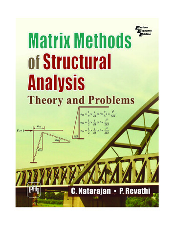
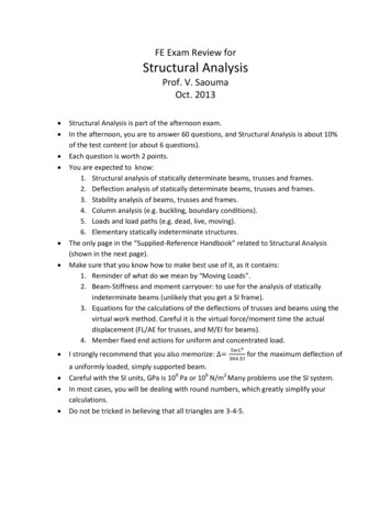
Chapter 1 — The Force Method ; 9(translation or rotation), the authors recommend use of the unit load methodbecause it is conceptually straight forward and easy to use.1.5.1 Sign ConventionThe following sign convention will be used for the force method: Counter-clockwise moments and displacements are positiveThis is often referred to as the right hand rule.When a member undergoes bending: Compression on a member's top fiber is positive bending Compression on a member's bottom fiber is negative bending. a) Positive bending top fiber compressionb) Negative bending bottom fiber compressionFigure 1.1: Bending sign convention
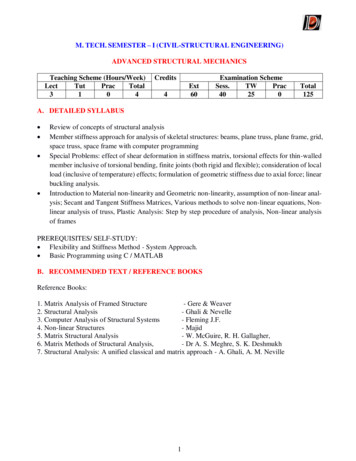
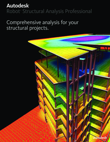
10 I Chapter 1 — The Force Method1.5.2 Example of an Indeterminate BeamAn example dealing with the analysis of a statically indeterminate beam usingthe force method is solved below.Example 1.5.2.1Determine the reactions at the supports for the statically indeterminatestructure shown in Fig. 1.2 by the force method. Use RB as the redundant.Take E 29000 ksi and I 446 in4.36kACB10ft12ftFigure 1.2: Statically indeterminate beam
Chapter 1 — The Force Method 1Solution:36 kACActual Beam12ftlofta) Actual beam36 kPrimary Structureb) Primary structureRBRedundant RB appliedRBC5BBc) Redundant RB appliedFigure 1.3: Two determinate structuresThe given indeterminate structure is split into two determinatestructures as shown in Fig. 1.3b and 1.3c choosing RB as the redundant force.The basic equation used is as given in Eq. 1.3. This is stated again below:M m dxElThe procedure will be followed as it is stated earlier in this section.Step 1.S/ u — ne 4 — 3 1Step 2Choose RB as the redundant force (in the problem statement).(1.3)
12 I Chapter 1 — The Force MethodStep 3The two determinate structures are shown below with Fig. 1.4aacted on by the applied loading, and Fig. 1.4c acted on by the redundantforce RB (unit load). The deflection at B for the statically determinatestructure (LX B)L due to applied loads can be obtained from Eq. 1.3 using thevalues of M and in. Figures 1.4a — 1.4d are used to calculate M and in.Redundant removed, applied loadingRedundant applied with unit magnitude1k36kAABxBCxx36kxc) FBD for ma) FBD for M1k36k10 k-ft792 k-ft tCxxb) Cut section for MxxCd) Cut section for inFigure 1.4: FBD for M and in (AB) and cut sectionsThe values for M and in will depend on the origin chosen and thecorresponding change in limits. In doing this, it may simplify theintegration and the final value of deflection will be the same.Step 4Deflection at B due to the applied loadsThe required values for calculation of deflection are tabulated in. Table 1.1.Table 1.1: Calculation of deflectionusing Fig. 1.3a and bPortion of the beamABBCOriginACLimitx 0 to x 10x 0 to x 12M36x — 792—36xmx — 100
Chapter 1 — The Force Method 13Calculate MPortion AB:Reaction forces: RA 36 k andMA 36 * (10 12) 792k-f tEquilibrium equation:M 792- 36x 0 — M 36x — 792Portion BC:Equilibrium equation: —M- 36x 0 — M —36xCalculate inPortion AB:Reaction forces: RA 1k and MA 1 * 10 10k-ftEquilibrium equation: m 10- x 0 — m x — 10Portion BC:Equilibrium equation: m 0It is to be noted that the value of M (shown in Table 1.1) iscalculated using Fig. 1.4a & 1.4b while the value of ni is calculated fromFig. 1.4c & d. The determinate structure shown in Fig. 1.4c is the samedeterminate structure as shown in Fig. 1.4a but acted on by a unitdownward load at B (with no given applied loads) as it is assumed that thevertical deflection at B is downward. If at the end of the calculation, thedeflection at B comes out to be positive, that means the actual deflection isdownward. On the other hand, if the final deflection at B comes out to benegative, it means that the actual deflection at B is upward.Substituting the values of M and 171 (from Table 1.1) in Eq. 1.3, thedeflection (AB) L (deflection at B due to the applied loads) is calculated as,AB Ef MmEl f1 (36x — 792)(x — 10)dxEl 0(1.6)
14 I Chapter 1 — The Force Method33600AB El(1.7)The deflection at B due to a unit value of the redundant force RB (ebb) isobtained from Fig. 1.5 as shown in Table 1.2 below.1kABxxa) FBD for m1kM m10 k-ftM mCAb) Cut section for inxFigure 1.5: FBD for m (obb) and cut sectionTable 1.2: Calculation of deflectionusing Fig. 1.4Portion of the beamABBCOriginACLimitx 0 to x 10x 0 to x 12M m0x — 10Substituting the values of M and m (M m) in eq. 1.3,10dx(x — 10)(x — 10)dx8bb "M El El 10(1.8)The deflection at B due to a unit value of the redundant force (RB) isobtained as,1000ebb 3E1(1.9)Step 5Equation of compatibility of displacement at joint B requires that,(LB)L — ('AR 0Where,(LB)RRB * (ebb)(1.10)
Chapter 1 - The Force Method 15This equation is essentially saying, the total vertical displacement at B hasto be zero as it is a roller joint.Substituting the values of (M I, and aibb) calculated above, Eq.1.10 can be rewritten as,33600El RB X10003E1 0Step 6Solving Eq. 1.11 above, RB can be obtained as,RB -100.8k TThis shows that RB is upward, not downward, as assumed in Fig. 1.3c.Step 7Once the redundant force (RB) is obtained, then the remainingreactions at A (RA and MA ) can easily be obtained from equilibriumequations.They are calculated using Fig. 1.6 as,E Ty 0EWA 0Ay 100.8 - 36 0Ay -64.8 kMA 100.8(10)- 36(22) 0 -4 MA -216 1{- f t ZJ36 kAyB---- MACAx .010 ft12 ftFigure 1.6: Final reactions for the indeterminate beam
16Chapter 1 — The Force MethodIt has been shown above by solving a simple example that whensolving a statically indeterminate structure by the force method; first, write thecorrect expressions for M and in, and then integrate the expression to solve fordeflection within the specified limits (consistent with the chosen origin).1.5.3 Structures with Several Redundant ForcesAs stated earlier, it is to be noted that if a structure has severalredundant forces (i.e. S/ 1), then indeterminate structural analysis of thestructure would involve obtaining redundant forces through solution ofsimultaneous equations. This will be followed by obtaining the remainingreactions at the supports (other than the redundant forces) through principles ofstatics as done in Ex. 1.5.2.1.The reader is advised to see other literature for detailed informationsuch as those found in the references of this book.1.6 Application of the Force Method to Indeterminate FramesThe basic procedure for analysis of statically indeterminate framesessentially remains the same as outlined in Sec. 1.5, and as illustrated for abeam in Example 1.5.2.1 in Sec. 1.5.Although the analysis of an indeterminate frame is, conceptually, verymuch similar to that of the beam, a frame consists of beams and columns so theanalysis is slightly more complicated. After following the example below, itwill be clear how to apply the force method to indeterminate frames.
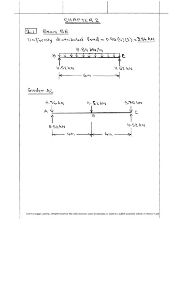
Chapter 1— The Force Method 171.6.1 Examples of an Indeterminate FrameA structural analysis dealing with a statically indeterminate frame by the forcemethod is shown below in Example 1.6.1.Example 1.6.1.1Determine the reactions at the supports of the frame shown in Fig. 1.7using the force method. A 100 in2, E 29000 ksi and I 833 in4.4 k/ftA8 ft10 ftFigure 1.7: Statically indeterminate frameSolutionThe procedure followed is as stated in Sec. 1.5.Step 1S/ nu- ne 4 — 3 1Step 2Choose MA as the redundant moment.Step 3The given statically indeterminate structure is split into twodeterminate structures as shown in Fig. 1.8, with the redundant momentremoved and with the applied loading as shown in Fig. 1.8b. In Fig. 1.8c,the frame is acted on by the redundant moment MA. The rotationaldeflection at A due to applied loads is OA, and due to the unit load, MA, is
18 Chapter 1 — The Force MethodMA xaAA. These rotations can be obtained from Eq. 1.3 by finding thevalues of M using Fig. 1.8b and respective values of m using Fig. 1.8c. Inboth cases HA and VA are found using static equilibrium equations.Note on symbols: In general, (04 HAHA) represents the horizontal deflectionat A due to a unit horizontal unit load at A (i.e. HA 1). Similarly,(SVAHA) represents the vertical deflection at A due to a unit horizontalunit load at A. Along the same lines, (SHAVA) and (,6vAvA) representthe horizontal and vertical deflection at A respectively due to a unitvertical load at A (i.e. VA 1).Note: The values for M and m will depend on the origin chosen (with thecorresponding change in limits). As can be expected, the final value ofdeflection will be the same irrespective of how it is done.This frame is statically indeterminate to the first degree. Since wechose the moment reaction at A as the redundant, the support at A willbecome a pin as seen in Fig. 1.8.4 k/ft4 k/ftMAHA AOA8 ftAMAann10ftVAa) Actual frameb) Primary structurec) Redundant MA appliedFigure 1.8: Given indeterminate and corresponding determinate structuresApplying the principle of superposition to the frame yields:— MA * aAA (1.12a)
Chapter 1 — The Force Method 19In this case, both 0A and MA * aAA are negative because they bothcreate a clockwise rotation at joint A. This is negative by the signconvention defined in section 1.5.1. Equation 1.12 can also be written as:(1.12b)9A MA * aAA Eq. 1.12b can also be found by considering that both 6A and MA * aAAcreate compression at the top fiber of member AB.Step 4Use the unit load method to calculate OA:4 k/ftk-ftA16kBBxxmA,xC16 k 8ka) Applied loadsb) Unit load MAFigure 1.9: Bending moments due to applied and unit loads—4 6A dx1r Etf Mine— (16x — 2x2) (1 —0El El8dx 2563E1Use virtual work (unit load method) to calculate aAA:Table 1.3: Deflection calculation forPortion of the beamABOriginALimitx 0 to x 8M16x — 2x21710x1— —8BCCx 0 to x 1000
20 I Chapter 1 - The Force MethodTable 1.4: Deflection calculation for aPortion of the beamABOriginALimitx 0 to x 8BCCx 0 to x 10x1 - 8M me0dx 1 i8f memo El El JOaAA2- 8) dx 3E1Step 5Equation of compatibility:OA MA * aAA 0Step 6Plugging in the values for deflection:2568—A ( 3E1)3E1 M- 0-* MA -32k-ft 0Here, MA is negative, which indicates that the moment is opposite toclockwise assumed direction of MA in Fig. 1.8c.Step 7Use static equilibrium equations to calculate the remaining supportreactions: 0HA MA32(4) 17c(8) 0 12 k T TETy 0:VA 12 - 32 0V A 20 k T
Chapter 1 — The Force Method 214 k/ft"1 -"—Aiiiiiiiiii20 k12 kFigure 1.10: Final reactions and moments for the indeterminate frameThis completes solution of the problem.1.7 Application of Force Method to Analysis of IndeterminateTrussesThe analysis procedure for a statically indeterminate truss follows thesame lines of beams and frames, discussed in Sec. 1.3. The basic equation usedfor calculating deflection is given by Eq. 1.4 and stated here again as,A v NnLAE(1.4)An example dealing with the analysis of a statically indeterminate truss issolved in Example 1.7.1.
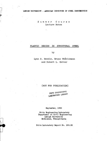
22 I Chapter 1 — The Force MethodExample 1.7.1Determine the reactions at the supports of the truss shown in Fig. 1.11using the force method. AE is constant.4ftA3ft4kFigure 1.11: Statically indeterminate trussSolutionStep 1Degree of indeterminacy b r — 2j 3 4 — 2(3) 1Step 2Choosing BC as the redundant, this member will be "cut" to make the trussstatically determinate.Step 3The given statically indeterminate structure is split into twodeterminate structures as shown in Fig. 1.12. Fig. 1.12b shows the structureunder the given loading, and Fig. 1.12c shows the truss with the redundantunit load applied.
Chapter 1 — The Force Method 23CIFBCBCBABA4k4k !ia) Actual Trussb) Primary structureAFsctBIFBC 8BCc) Redundant FBC appliedFigure 1.12: Statically indeterminate and corresponding determinate trussesApplying the principle of superposition to the truss yields:FBC * 8BC(1.13) Step 4Use the unit load method to calculate ABC:Calculate N and 17 for each member in both cases: real load and virtual unitload as is shown in Fig. 1.13.-FIEF; 0:—4 FAc 0 F Ac 5 k (T)-- 0:FAR F Ac4ka) Calculation of FAR and F Ac 0F AB —3 k (C)
24 I Chapter 1 — The Force Method0ir 1k5k1kt0BAb) Calculation of N0c) Calculation of nFigure 1.13: Calculation of forces for N and it1(0)4ABC ""dv nANEL - Ct(A5;"A—E3)3)4(1.14)oUse the unit load method to calculate SBC:8BC 02 (3) 12 (4) - 4AE AE AE AE AEn2 L 02(5) (1.15)Step 5The compatibility equation given by Eq. 1.13 is repeated below.(1.13)/IBC FRC * 8I3C Step 6From equation (1.13) —4 0 FBc * —A4E 0Fgc 0Using this result, the forces in other members and the support reactions canbe calculated easily using the method of joints.
Chapter 1 — The Force Method 25Step 7The method of join
Problems 27 CHAPTER 2 - DISPLACEMENT METHOD OF ANALYSIS: SLOPE-DEFLECTION METHOD 29 2.1 Basic Concepts of the Displacement Method 29 2.2 Basic Procedure of the Slope-Deflection Method 30 2.2.1 Slope-Deflection Equations 30 2.2.2 Sign Convention for Displacement Methods 31 2.2.3 Fixed-End Moments 32