Transcription
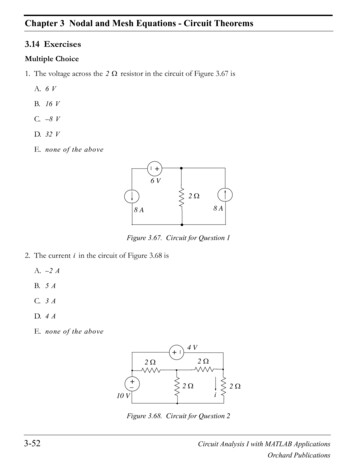
Chapter 3 Nodal and Mesh Equations - Circuit Theorems3.14 ExercisesMultiple Choice1. The voltage across the 2 Ω resistor in the circuit of Figure 3.67 isA. 6 VB. 16 VC. – 8 VD. 32 VE. none of the above 6V 2Ω 8A8AFigure 3.67. Circuit for Question 12. The current i in the circuit of Figure 3.68 isA. – 2 AB. 5 AC. 3 AD. 4 A E. none of the above4V2Ω2Ω 10 V2Ω2ΩiFigure 3.68. Circuit for Question 23-52Circuit Analysis I with MATLAB ApplicationsOrchard Publications
Exercises3. The node voltages shown in the partial network of Figure 3.69 are relative to some referencenode which is not shown. The current i isA. – 4 AB. 8 3 AC. – 5 AD. – 6 AE. none of the above6V 4V8V8V2Ω 12 V2Ωi 6V8V13 V2ΩFigure 3.69. Circuit for Question 34. The value of the current i for the circuit of Figure 3.70 isA. – 3 AB. – 8 AC. – 9 AD. 6 AE. none of the above6Ω12 V 3Ω6Ω i8A3ΩFigure 3.70. Circuit for Question 4Circuit Analysis I with MATLAB ApplicationsOrchard Publications3-53
Chapter 3 Nodal and Mesh Equations - Circuit Theorems5. The value of the voltage v for the circuit of Figure 3.71 isA. 4 VB. 6 VC. 8 VD. 12 VE. none of the above 2A2ΩvX 2Ω 2vX v Figure 3.71. Circuit for Question 56. For the circuit of Figure 3.72, the value of k is dimensionless. For that circuit, no solution is possible if the value of k isA. 2B. 1C. D. 0E. none of the above 2A4Ωv4Ω kv Figure 3.72. Circuit for Question 63-54Circuit Analysis I with MATLAB ApplicationsOrchard Publications
Exercises7. For the network of Figure 3.73, the Thevenin equivalent resistance R TH to the right of terminalsa and b isA. 1B. 2C. 5D. 10E. none of the abovea3Ω2Ω2Ω4ΩR TH2Ω2Ωb2ΩFigure 3.73. Network for Question 78. For the network of Figure 3.74, the Thevenin equivalent voltage V TH across terminals a and b isA. – 3 VB. – 2 VC. 1 VD. 5 VE. none of the above a2V2Ω2Ω2AbFigure 3.74. Network for Question 8Circuit Analysis I with MATLAB ApplicationsOrchard Publications3-55
Chapter 3 Nodal and Mesh Equations - Circuit Theorems9. For the network of Figure 3.75, the Norton equivalent current source I N and equivalent parallelresistance R N across terminals a and b areA. 1 A, 2 ΩB. 1.5 A, 25 ΩC. 4 A, 2.5 ΩD. 0 A, 5ΩE. none of the abovea5Ω2A5Ω2AbFigure 3.75. Network for Question 910. In applying the superposition principle to the circuit of Figure 3.76, the current i due to the 4 Vsource acting alone isA. 8 AB. – 1 AC. 4 AD. – 2 AE. none of the abovei2Ω2Ω8A2Ω 4V Figure 3.76. Network for Question 103-56Circuit Analysis I with MATLAB ApplicationsOrchard Publications
ExercisesProblems1. Use nodal analysis to compute the voltage across the 18 A current source in the circuit of Figure3.77. Answer: 1.12 V4Ω8Ω4Ω–15Ω–1 –1–16Ωv 18 A18 A12 A10 Ω–1–1 24 AFigure 3.77. Circuit for Problem 12. Use nodal analysis to compute the voltage v 6 Ω in the circuit of Figure 3.78. Answer: 21.6 V36 V 12 Ω15 Ω 4Ω12 A6Ω18 Av6 Ω 24 AFigure 3.78. Circuit for Problem 23. Use nodal analysis to compute the current through the 6 Ω resistor and the power supplied (orabsorbed) by the dependent source shown in Figure 3.79. Answers: – 3.9 A, – 499.17 w4. Use mesh analysis to compute the voltage v 36A in Figure 3.80. Answer: 86.34 V5. Use mesh analysis to compute the current through the i 6 Ω resistor, and the power supplied (orabsorbed) by the dependent source shown in Figure 3.81. Answers: – 3.9 A, – 499.33 w6. Use mesh analysis to compute the voltage v 10 Ω in Figure 3.82. Answer: 0.5 VCircuit Analysis I with MATLAB ApplicationsOrchard Publications3-57
Chapter 3 Nodal and Mesh Equations - Circuit Theorems18 A15 Ω12 ΩiX 6Ω4Ω i6 Ω 12 A5i X24 A36 V 120 V Figure 3.79. Circuit for Problem 3240 V3Ω4Ω8Ω12 Ω v 36A4Ω36 A12 A6Ω 24 AFigure 3.80. Circuit for Problem 418 A15 Ω12 ΩiX6Ω4Ω 5i X 12 A i6 Ω 36 V24 AFigure 3.81. Circuit for Problem 53-58Circuit Analysis I with MATLAB ApplicationsOrchard Publications
Exercises10i X15 Ω12 Ω4Ω 8ΩiX6Ω 12 Vv 10 Ω10 Ω 24 VFigure 3.82. Circuit for Problem 67. Compute the power absorbed by the 10 Ω resistor in the circuit of Figure 3.83 using any method.Answer: 1.32 w2Ω 3Ω 12 V6Ω 10 Ω 24 V36 VFigure 3.83. Circuit for Problem 78. Compute the power absorbed by the 20 Ω resistor in the circuit of Figure 3.84 using anymethod. Answer: 73.73 w 20 Ω12 V3Ω2Ω6A8AFigure 3.84. Circuit for Problem 89. In the circuit of Figure 3.85:a. To what value should the load resistor R LOAD should be adjusted to so that it will absorbmaximum power? Answer: 2.4 ΩCircuit Analysis I with MATLAB ApplicationsOrchard Publications3-59
Chapter 3 Nodal and Mesh Equations - Circuit Theoremsb. What would then the power absorbed by R LOAD be? Answer: 135 w 36 V15 Ω12 ΩR LOAD6Ω4Ω18 A12 AFigure 3.85. Circuit for Problem 910. Replace the network shown in Figure 3.86 by its Norton equivalent.Answers: i N 0, R N 23.75 Ωa15 Ω4ΩiX5Ω5iXbFigure 3.86. Circuit for Problem 1011. Use the superposition principle to compute the voltage v 18A in the circuit of Figure 3.87.Answer: 1.12 V4Ω8Ω4Ω12 A–15Ω–1 –110 Ωv 18 A18 A–1–16Ω –124 AFigure 3.87. Circuit for Problem 113-60Circuit Analysis I with MATLAB ApplicationsOrchard Publications
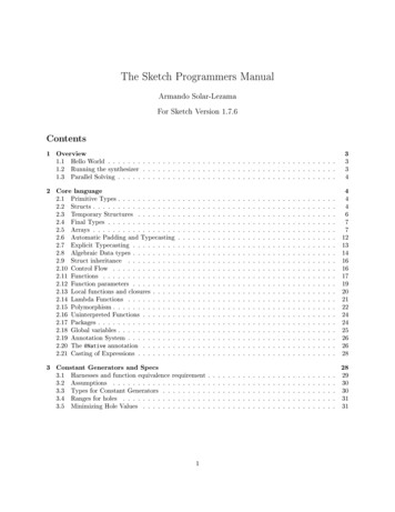
Exercises12. Use the superposition principle to compute voltage v 6 Ω in the circuit of Figure 3.88.Answer: 21.6 V36 V 12 Ω15 Ω 6Ω4Ω 18 A12 Av6 Ω24 AFigure 3.88. Circuit for Problem 1213.In the circuit of Figure 3.89, v S1 and v S2 are adjustable voltage sources in the range– 50 V 50 V, and R S1 and R S2 represent their internal resistances. Table 3.4 shows the resultsof several measurements. In Measurement 3 the load resistance is adjusted to the same value asMeasurement 1, and in Measurement 4 the load resistance is adjusted to the same value as Measurement 2. For Measurements 5 and 6 the load resistance is adjusted to 1 Ω . Make the necessary computations to fill-in the blank cells of this table.TABLE 3.4 Table for Problem 13Measurement123456Switch S 1Switch S sedClosedClosedv S1 (V)v S2 (V)i LOAD (A)4800360 421824166 50150Answers: – 15 V , – 7 A , 11 A , – 24 VCircuit Analysis I with MATLAB ApplicationsOrchard Publications3-61
Chapter 3 Nodal and Mesh Equations - Circuit Theorems R S1 1 ΩR S2 v S1i LOAD1Ω vS2S1S2v LOADAdjustableResistiveLoad Figure 3.89. Network for Problem 1314. Compute the efficiency of the electrical system of Figure 3.90. Answer: 76.6%0.8 Ω0.5 ΩvS100 A1st FloorLoad 480 Vi2i180 A2nd FloorLoad0.5 Ω0.8 ΩFigure 3.90. Electrical system for Problem 1415. Compute the regulation for the 2st floor load of the electrical system of Figure 3.91.Answer: 36.4%0.8 Ω0.5 ΩVS100 A1st FloorLoad 480 Vi1 i280 A2nd FloorLoad0.5 Ω0.8 ΩFigure 3.91. Circuit for Problem 153-62Circuit Analysis I with MATLAB ApplicationsOrchard Publications
Exercises3Ω3Ω 12 ViX6Ω 16. Write a set of nodal equations and then use MATLAB to compute i LOAD and v LOAD for the circuit of Example 3.10 which is repeated as Figure 3.92 for convenience.Answers: – 0.96 A, – 7.68 V7Ω20i X10 Ω4Ω5Ω v LOADi LOADRL 8ΩFigure 3.92. Circuit for Problem 16Circuit Analysis I with MATLAB ApplicationsOrchard Publications3-63
Chapter 3 Nodal and Mesh Equations - Circuit Theorems3.15 Answers to ExercisesMultiple Choice1. E The current entering Node A is equal to the current leaving that node. Therefore, there is nocurrent through the 2 Ω resistor and the voltage across it is zero. 6V 2Ω 8A8A8A8AA2. C From the figure below, V AC 4 V . Also, V AB V BC 2 V and V AD 10 V . Then,V BD V AD – V AB 10 – 2 8 V a n d V CD V BD – V BC 8 – 2 6 V . T h e r e f o r e , i 6 2 3 A.2ΩA4V2ΩB C2Ω 10 V2ΩiD3. A From the figure below we observe that the node voltage at A is 6 V relative to the referencenode which is not shown. Therefore, the node voltage at B is 6 12 18 V relative to thesame reference node. The voltage across the resistor is V BC 18 – 6 12 V and the direction of current through the 3 Ω resistor is opposite to that shown since Node B is at a higherpotential than Node C. Thus i – 12 3 – 4 A 6V3-64iC3Ω 8V12 V B8V2Ω 2Ω 6VA 4V8V13 VCircuit Analysis I with MATLAB ApplicationsOrchard Publications
Answers to Exercises4. E We assign node voltages at Nodes A and B as shown below.A6Ω12 V 3ΩBi8A6Ω 3ΩAt Node AV A – 12 V A V A – V B----------------- ------ ------------------- 0636and at Node BVB – VA VB------------------- ------ 833These simplify to2--- V A – 1--- V B 233and21– --- V A --- V B 833Multiplication of the last equation by 2 and addition with the first yields V B 18 and thusi – 18 3 – 6 A .5. E Application of KCL at Node A of the circuit below yieldsA vX 2A2Ω 2Ωv 2vX v – 2v--v- ----------------X- 222orv – vX 2Also by KVLCircuit Analysis I with MATLAB ApplicationsOrchard Publications3-65
Chapter 3 Nodal and Mesh Equations - Circuit Theoremsv v X 2v Xand by substitutionv X 2v X – v X 2orvX 1and thusv v X 2v X 1 2 1 3 V6. A Application of KCL at Node A of the circuit below yieldsA 2A4Ω4Ω kv v v v – kv--- -------------- 244or1--- ( 2v – kv ) 24and this relation is meaningless if k 2 . Thus, this circuit has solutions only if k 2 .7. B The two 2 Ω resistors on the right are in series and the two 2 Ω resistors on the left shown inthe figure below are in parallel.a3Ω4ΩR TH2Ωb2Ω2Ω2Ω2ΩStarting on the right side and proceeding to the left we get 2 2 4 , 4 4 2 , 2 2 4 ,4 ( 3 2 2 ) 4 ( 3 1 ) 4 4 2 Ω .3-66Circuit Analysis I with MATLAB ApplicationsOrchard Publications
Answers to Exercises 8. A Replacing the current source and its 2 Ω parallel resistance with an equivalent voltage sourcein series with a 2 Ω resistance we get the network shown below.2Va2Ω2Ωi4Vb By Ohm’s law,4–2i ------------ 0.5 A2 2and thusv TH v ab 2 0.5 ( – 4 ) – 3 V9. D The Norton equivalent current source I N is found by placing a short across the terminals aand b. This short shorts out the 5 Ω resistor and thus the circuit reduces to the one shownbelow.a5Ω2AbI SC I N2AABy KCL at Node A,IN 2 2and thus I N 0The Norton equivalent resistance R N is found by opening the current sources and looking tothe right of terminals a and b. When this is done, the circuit reduces to the one shown below.Circuit Analysis I with MATLAB ApplicationsOrchard Publications3-67
Chapter 3 Nodal and Mesh Equations - Circuit Theoremsa5Ω5ΩbTherefore, R N 5 Ω and the Norton equivalent circuit consists of just a 5 Ω resistor.10. B With the 4 V source acting alone, the circuit is as shown below.Ai 2Ω 2Ω 4V2Ω BWe observe that v AB 4 V and thus the voltage drop across each of the 2 Ω resistors to theleft of the 4 V source is 2 V with the indicated polarities. Therefore,i –2 2 –1 AProblems1. We first replace the parallel conductances with their equivalents and the circuit simplifies to thatshown below.v 1 12 Ω–1v 2 15 Ωv3321–1 4Ω12 A–1v 18 A18 A 6Ω–124 AApplying nodal analysis at Nodes 1, 2, and 3 we get:Node 1:16v 1 – 12v2 12Node 2:– 12 v 1 27v 2 – 15v 3 – 183-68Circuit Analysis I with MATLAB ApplicationsOrchard Publications
Answers to ExercisesNode 3:– 15 v 2 21v 3 24Simplifying the above equations, we get:4v 1 – 3v 2 3– 4 v 1 9v 2 – 5v 3 – 6– 5 v 2 7v 3 8Addition of the first two equations above and grouping with the third yields6v 2 – 5v 3 – 3– 5 v 2 7v 3 8For this problem we are only interested in v 2 v 18 A . Therefore, we will use Cramer’s rule tosolve for v 2 . Thus,Dv 2 -----2 D 2 – 3 – 5 – 21 40 198 7 6 – 5 42 – 25 17–5 7andv 2 v 18 A 19 17 1.12 V2. Since we cannot write an expression for the current through the 36 V source, we form a combined node as shown on the circuit below.36 V v11v312 Ω 2 v 2 15 Ω 3 4Ω12 A6Ω18 Av6 Ω 24 AAt Node 1 (combined node):v1 – v2 v3 – v2 v3v----1- --------------- ---------------- ----- – 12 – 24 0461215and at Node 2,Circuit Analysis I with MATLAB ApplicationsOrchard Publications3-69
Chapter 3 Nodal and Mesh Equations - Circuit Theoremsv2 – v1 v2 – v3--------------- ---------------- – 181215Also,v 1 – v 3 36Simplifying the above equations, we get:713--- v 1 – ------ v 2 ------ v 3 3630320311– ------ v 1 ------ v 2 – ------ v 3 – 18201512– v 3 36v1Addition of the first two equations above and multiplication of the third by – 1 4 yields1--- v 3 18--- v 1 16411– --- v 1 --- v 3 – 944and by adding the last two equations we get5----v 912 3or108v 3 v 6 Ω --------- 21.6V5Check with MATLAB:format ratR [1/3 3/20 7/30; 1/12 3/20 1/15; 1 0 1];I [36 18 36]';V R\I;fprintf('\n'); disp('v1 '); disp(V(1)); disp('v2 '); disp(V(2)); disp('v3 '); disp(V(3))v1 288/5v2 -392/5v3 108/53. We assign node voltages3-70v1 , v2 , v3 , v4and current i Y as shown in the circuit below. Then,Circuit Analysis I with MATLAB ApplicationsOrchard Publications
Answers to Exercisesv1 – v2v----1- --------------- 18 – 12 0412andv2 – v1 v2 – v3 v2 – v4--------------- ---------------- ---------------- 012126v118 A15 Ω12 Ω v 2v3iX 6Ω4Ωi6 Ωv4 12 A 36 V5i XiY24 ASimplifying the last two equations above, we get11--- v 1 – ------ v 2 – 6312and11119– ------ v 1 ------ v 2 – ------ v 3 – --- v 4 01215660v –v12512- , v 3 5i X and v 4 36 V . Then v 3 ------ ( v 1 – v 2 ) and byNext, we observe that i X --------------12substitution into the last equation above, we get191151– ------ v 1 ------ v 2 – ------ ------ ( v 1 – v 2 ) – --- 36 060615 1212or131– --- v 1 ------ v 2 6990Thus, we have two equations with two unknowns, that is,11--- v 1 – ------ v 2 – 6312311– --- v 1 ------ v 2 6909Circuit Analysis I with MATLAB ApplicationsOrchard Publications3-71
Chapter 3 Nodal and Mesh Equations - Circuit TheoremsMultiplication of the first equation above by 1 3 and addition with the second yields19------ v 2 460orv 2 240 19We find v 1 from11--- v 1 – ------ v 2 – 6312Thus,1- 2401--- v 1 – ---- --------- – 612 193orv 1 – 282 19Now, we find v 3 from55 282 240 -------------------- – --------- – 435v 3 ------ ( v 1 – v 2 ) ------ –1212 193819 Therefore, the node voltages of interest are:v 1 – 282 19 Vv 2 240 19 Vv 3 – 435 38 Vv 4 36 VThe current through the 6 Ω resistor isv2 – v474240 19 – 36- ------------------------------- – ------ – 3.9 Ai 6 Ω --------------6619To compute the power supplied (or absorbed) by the dependent source, we must first find thecurrent i Y . It is found by application of KCL at node voltage v 3 . Thus,v3 – v2i Y – 24 – 18 --------------- 015or3-72Circuit Analysis I with MATLAB ApplicationsOrchard Publications
Answers to Exercises– 435 38 – 240 19i Y 42 – 5 38 1657 42 ------------------- -----------1538and1657--------------- – 499.17 w--------- ------------ – 72379p v 3 i Y – 4353814538that is, the dependent source supplies power to the circuit.4Ω 120 V 4. Since we cannot write an expression for the 36 A current source, we temporarily remove it andwe form a combined mesh for Meshes 2 and 3 as shown below.i6i58Ω12 Ω4Ω12 Ai1i2i3240 V3Ω6Ωi424 AMesh 1:i 1 12Combined mesh (2 and 3):– 4i 1 12i 2 18i 3 – 6i 4 – 8i 5 – 12i 6 0or– 2i 1 6i 2 9i 3 – 3i 4 – 4i 5 – 6i 6 0We now re-insert the 36 A current source and we write the third equation asi 2 – i 3 36Mesh 4:i 4 – 24Mesh 5:– 8 i 2 12i 5 120orCircuit Analysis I with MATLAB ApplicationsOrchard Publications3-73
Chapter 3 Nodal and Mesh Equations - Circuit Theorems– 2 i 2 3i 5 30Mesh 6:– 12 i 3 15i 6 – 240or– 4 i 3 5i 6 – 80Thus, we have the following system of equations: 12i1– 2i 1 6i 2 9i 3 – 3i 4 – 4i 5 – 6i 6 0i2 – i3 36 – 24i4–2 i2 3i 5–4 i3 30 5i 6 – 80and in matrix form0–301000–400300–60005Ri1i2i3 i4i5i6I 12036– 2430– 80 09–100–4 0610–20 1–20000VWe find the currents i 1 through i 6 with the following MATLAB code:R [1 0 0 0 0 0; 2 6 9 3 4 6;.0 1 1 0 0 0; 0 0 0 1 0 0;.0 2 0 0 3 0; 0 0 4 0 0 5];V [12 0 36 24 30 80]';I R\V;fprintf('\n');.fprintf('i1 %7.2f A \t', I(1));.fprintf('i2 %7.2f A \t', I(2));.fprintf('i3 %7.2f A \t', I(3));.fprintf('\n');.3-74Circuit Analysis I with MATLAB ApplicationsOrchard Publications
Answers to Exercisesfprintf('i4 %7.2f A \t', I(4));.fprintf('i5 %7.2f A \t', I(5));.fprintf('i6 %7.2f A \t', I(6));.fprintf('\n')i1 12.00 Ai4 -24.00 Ai2 i5 6.27 A14.18 Ai3 -29.73 Ai6 -39.79 A 120 V4Ω Now, we can find the voltage v 36 A by application of KVL around Mesh 3. Thus,240 Vi6i58Ω3Ω12 Ω 4Ω12 Ai136 Ai2v 36 A i36Ωi424 Av 36 A v 12 Ω v 6 Ω 12 [ ( – 29.73 ) – ( – 39.79 ) ] 6 [ ( – 29.73 ) – ( 24.00 ) ]orv 36 A 86.34 VTo verify that this value is correct, we apply KVL around Mesh 2. Thus, we must show thatv 4 Ω v 8 Ω v 36 A 0By substitution of numerical values, we find that4 [ 6.27 – 12 ] 8 [ 6.27 – 14.18 ] 86.34 0.145. This is the same circuit as that of Problem 3. We will show that we obtain the same answers usingmesh analysis.We assign mesh currents as shown below.Circuit Analysis I with MATLAB ApplicationsOrchard Publications3-75
Chapter 3 Nodal and Mesh Equations - Circuit Theorems18 A15 Ω12 Ωi5iX6Ωi6 Ω4Ωi1 12 Ai2 i35i Xi4 36 V24 AMesh 1:i 1 12Mesh 2:– 4i 1 22i 2 – 6i 3 – 12i 5 – 36or– 2i 1 11i 2 – 3i 3 – 6i 5 – 18Mesh 3:– 6 i 2 21i 3 – 15i 5 5i X 36and since i X i 2 – i 5 , the above reduces to– 6 i 2 21i 3 – 15i 5 5i 2 – 5i 5 36or– i 2 21i 3 – 20i 5 36Mesh 4:i 4 – 24Mesh 5:i 5 18Grouping these five independent equations we get: 12i1– 2i 1 11i 2 – 3i 3– 6i 5 – 18– i 2 21i 3– 20i 5 36i4 – 24i 5 18and in matrix form,3-76Circuit Analysis I with MATLAB ApplicationsOrchard Publications
Answers to Exercises0 00 –60 – 201 00 1Ri112– 1836– 2418i2 i3i4 i5 0–32100 011–100 1–2000VIWe find the currents i 1 through i 5 with the following MATLAB code:R [1 0 0 0 0 ; 2 11 3 0 6; 0 1 21 0 20; .0 0 0 1 0; 0 0 0 0 1];V [12 18 36 24 18]';I R\V;fprintf('\n');.fprintf('i1 %7.2f A \t', I(1));.fprintf('i2 %7.2f A \t', I(2));.fprintf('i3 %7.2f A \t', I(3));.fprintf('\n');.fprintf('i4 %7.2f A \t', I(4));.fprintf('i5 %7.2f A \t', I(5));.fprintf('\n')i1 12.00 Ai4 -24.00 Ai2 i5 15.71 A18.00 Ai3 19.61 ABy inspection,i 6 Ω i 2 – i 3 15.71 – 19.61 – 3.9 ANext,p 5i 5i X ( i 3 – i 4 ) 5 ( i 2 – i 5 ) ( i 3 – i 4 )X 5 ( 15.71 – 18.00 ) ( 19.61 24.00 ) – 499.33 wThese are the same answers as those we found in Problem 3.6. We assign mesh currents as shown below and we write mesh equations.Circuit Analysis I with MATLAB ApplicationsOrchard Publications3-77
Chapter 3 Nodal and Mesh Equations - Circuit Theorems10i Xi415 Ω12 Ω4Ω 12 V i2i1 8ΩMesh 1:iX6Ωv 10 Ωi310 Ω 24 V24i 1 – 8i 2 – 12i 4 – 24 – 12 0or6i 1 – 2i 2 – 3i 4 9Mesh 2:– 8 i 1 29i 2 – 6i 3 – 15i 4 – 24Mesh 3:– 6 i 2 16i 3 0or– 3 i 2 8i 3 0Mesh 4:i 4 10i X 10 ( i 2 – i 3 )or10i 2 – 10i 3 – i 4 0Grouping these four independent equations we get:6i 1 – 2i 2– 3i 4 9– 8 i 1 29i 2 – 6i 3 – 15i 4 – 24– 3 i 2 8i 3 010i 2 – 10i 3 – i 4 0and in matrix form,3-78i2 i3i4 9– 2400 Ri1 –2 0 –329 – 6 – 15–3 8 010 – 10 – 1 6–800IVCircuit Analysis I with MATLAB ApplicationsOrchard Publications
Answers to ExercisesWe find the currents i 1 through i 4 with the following MATLAB code:R [6 2 0 3; 8 29 6 15; 0 3 8 0 ; 0 10 10 1];V [9 24 0 0]';I R\V;fprintf('\n');.fprintf('i1 %7.2f A \t', I(1));.fprintf('i2 %7.2f A \t', I(2));.fprintf('i3 %7.2f A \t', I(3));.fprintf('i4 %7.2f A \t', I(4));.fprintf('\n')i1 1.94 Ai2 0.13 Ai3 0.05 Ai4 0.79 ANow, we find v 10 Ω by Ohm’s law, that is,v 10 Ω 10i 3 10 0.05 0.5 VThe same value is obtained by computing the voltage across the 6 Ω resistor, that is,v 6 Ω 6 ( i 2 – i 3 ) 6 ( 0.13 – 0.05 ) 0.48 V7. Voltage-to-current source transformation yields the circuit below.2Ω6A6Ω3Ω10 Ω6A8ABy combining all current sources and all parallel resistors except the 10 Ω resistor, we obtain thesimplified circuit below.1Ω10 Ω4AApplying the current division expression, we get41i 10 Ω --------------- 4 ------ A111 10and thus4 2162--------- 1.32 wp 10 Ω i 10 Ω ( 10 ) ------ 10 --------- 10 160 11 121121Circuit Analysis I with MATLAB ApplicationsOrchard Publications3-79
Chapter 3 Nodal and Mesh Equations - Circuit Theorems8. Current-to-voltage source transformation yields the circuit below.2Ω20 Ω12 V3Ω i12 V 24 VFrom this series circuit,48Σvi ------- ------ A25ΣRand thus48 223042p 20 Ω i ( 20 ) ------ 20 ------------ 20 73.73 w 25 6259. We remove R LOAD from the rest of the rest of the circuit and we assign node voltages v 1 , v 2 , andv 3 . We also form the combined node as shown on the circuit below. 36 V31v12 v 2 15 Ω12 Ω x6Ω4Ω12 Av318 A yNode 1:v1 – v2v3 – v2 v3v----1- --------------- – 12 --------------- ----- 0461215or173--- v 1 – ------ v 2 ------ v 3 1233020Node 2:3-80Circuit Analysis I with MATLAB ApplicationsOrchard Publications
Answers to Exercisesv2 – v1 v2 – v3--------------- ---------------- – 181215or31- v ----1- v – 18v 2 – ----– ----1201215 3Also,v 1 – v 3 36For this problem, we are interested only in the value of v 3 which is the Thevenin voltage v TH ,and we could find it by Gauss’s elimination method. However, for convenience, we will groupthese three independent equations, express these in matrix form, and use MATLAB for theirsolution.713--- v 1 – ------ v 2 ------ v 3 123032031- v – 181- v ----v – ----– ----12 1 20 2 15 3– v 3 36v1and in matrix form,Gv2v3 12– 1836 1– ---- 15–1v1 7-----30 1 3--- – -----3 2031- ----– ----12 201 0VIWe find the voltages v 1 through v 3 with the following MATLAB code:G [1/3 3/20 7/30; 1/12 3/20 1/15; 1 0 1];I [12 18 36]'; V G\I;fprintf('\n');.fprintf('v1 %7.2f V \t', V(1)); fprintf('v2 %7.2f V \t', V(2)); fprintf('v3 %7.2f V \t', V(3));fprintf('\n')v1 0.00 Vv2 -136.00 Vv3 -36.00 VThus,v TH v 3 – 36 VCircuit Analysis I with MATLAB ApplicationsOrchard Publications3-81
Chapter 3 Nodal and Mesh Equations - Circuit TheoremsTo find R TH we short circuit the voltage source and we open the current sources. The circuit thenreduces to the resistive network below. x15 Ω12 Ω6Ω4ΩR TH yWe observe that the resistors in series are shorted out and thus the Thevenin resistance is the parallel combination of the 4 Ω and 6 Ω resistors, that is,4 Ω 6 Ω 2.4 Ωand the Thevenin equivalent circuit is as shown below. 36 V2.4 ΩNow, we connect the load resistor R LOAD at the open terminals and we get the simple series circuit shown below. R LOAD 2.4 Ω36 V2.4 Ωa. For maximum power transfer,R LOAD 2.4 Ωb. Power under maximum power transfer condition is3-82Circuit Analysis I with MATLAB ApplicationsOrchard Publications
Answers to Exercises23622p MAX i R LOAD --------------------- 2.4 7.5 2.4 135 w 2.4 2.4 10. We assign a node voltage Node 1 and a mesh current for the mesh on the right as shown below.iXv1115 Ω4Ω5iXa5ΩiXiXbAt Node 1:v----1- i X 5i X4Mesh on the right:( 15 5 )i X v 1and by substitution into the node equation above,20i----------X i X 5i X4or6i X 5i Xbut this can only be true if i X 0 .Then,v OCv ab5 i5 0i N -------- ------ -------------X ------------ 0RNRNRNRNThus, the Norton current source is open as shown below.aRNiXbTo find R N we insert a 1 A current source as shown below.Circuit Analysis I with MATLAB ApplicationsOrchard Publications3-83
Chapter 3 Nodal and Mesh Equations - Circuit TheoremsiX v BvAA15 Ω4Ω5Ω5iXaBiX1AiXbAt Node A:vA vA – vB----- ----------------- 5i X415Butv B ( 5 Ω ) i X 5i Xand by substitution into the above relationvA – vBv----A- ---------------- vB415or1916------ v A – ------ v B 06015At Node B:vB – vA vB---------------- ----- 1155or14– ------ v A ------ v B 11515For this problem, we are interested only in the value of v B which we could find by Gauss’s elimination method. However, for convenience, we will use MATLAB for their solution.19------ v A – 16------ v B 0601541– ------ v A ------ v B 115153-84Circuit Analysis I with MATLAB ApplicationsOrchard Publications
Answers to Exercisesand in matrix form,vAvB 01 VI 19 16------ – -----60 151 4 – ------ -----15 15GWe find the voltages v 1 and v 2 with the following MATLAB code:G [19/60 16/15; 1/15 4/15];I [0 1]'; V G\I;fprintf('\n');.fprintf('vA %7.2f V \t', V(1)); fprintf('vB %7.2f V \t', V(2));fprintf('\n')vA 80.00 VvB 23.75 VNow, we can find the Norton equivalent resistance from the relationV abVR N ------- -----B- 23.75 ΩI SC111. This is the same circuit as that of Problem 1. Let v' 18A be the voltage due to the 12 A currentsource acting alone. The simplified circuit with assigned node voltages is shown below wherethe parallel conductances have been replaced by their equivalents.v 1 12 Ω–1v 2 15 Ω–1v3 4Ω–1v' 18A6Ω–112 A The nodal equations at the three nodes are16v 1 – 12v 2 12– 12v 1 27v 2 – 15v 3 0– 15 v 2 21v 3 0orCircuit Analysis I with MATLAB ApplicationsOrchard Publications3-85
Chapter 3 Nodal and Mesh Equations - Circuit Theorems4v 1 – 3v 2 3– 4v 1 9v 2 – 5v 3 0– 5 v 2 7v 3 0Since v 2 v' 18A , we only need to solve for v 2 . Adding the first 2 equations above and groupingwith the third we obtain6v 2 – 5v 3 3– 5 v 2 7v 3 0Multiplying the first by 7 and the second by 5 we get42v 2 – 35v 3 21– 25 v 2 35v 3 0and by addition of these we get21v 2 v' 18A ------ V17Next, we let v'' 18A be the voltage due to the 18 A current source acting alone. The simplified circuit with assigned node voltages is shown below where the parallel conductances have beenreplaced by their equivalents.vA12 Ω–1v B 15 Ω–1vC 4Ω–16Ωv'' 18A18 A–1 The nodal equations at the three nodes are16v A – 12v B 0– 12v A 27v B – 15v C – 18– 15 v B 21v C 0or3-86Circuit Analysis I with MATLAB ApplicationsOrchard Publications
Answers to Exercises4v A – 3v B 0– 4v A 9v B – 5v C – 6– 5 v B 7v C 0Since v B v'' 18A , we only need to solve for v B . Adding the first 2 equations above and grouping with the third we obtain6v B – 5v C – 6– 5 v B 7v C 0Multiplying the first by 7 and the second by 5 we get42v B – 35v C – 42– 25 v B 35v C 0and by addition of these we get– 42v B v'' 18A --------- V17Finally, we let v''' 18A be the voltage due to the 24 A current source acting alone. The simplifiedcircuit with assigned node voltages is shown below where the parallel conductances have beenreplaced by their equivalents.v X 12 Ω–1v Y 15 Ω–1vZ 4Ω–1v''' 18A6Ω–124 A The nodal equations at the three nodes are16v X – 12v Y 0– 12v A 27v Y – 15v Z 0– 15 v B 21v Z 24orCircuit Analysis I with MATLAB ApplicationsOrchard Publications3-87
Chapter 3 Nodal and Mesh Equations - Circuit Theorems4v X – 3v Y 0– 4v X 9v Y – 5v Z 0– 5 v Y 7v Z 8Since v Y v''' 18A , we only need to solve for v Y . Adding the first 2 equations above and groupingwith the third we obtain6v Y – 5v Z 0– 5 v Y 7v Z 0Multiplying the first by 7 and the second by 5 we get42v Y – 35v Z 0– 25 v Y 35v Z 40and by addition of these we get40v Y v''' 18A ------ V17and thus42- 40------ 1.12 V------ 19------------- –v 18A v' 18A v'' 18A v''' 18A 211717 17 17This is the same answer as in Problem 1.12. This is the same circuit as that of Problem 2. Let v' 6 Ω be the voltage due to the 12 A currentsource acting alone. The simplified circuit is shown below.12 Ω15 Ω 4Ω12 A6Ωv' 6 Ω The 12 Ω and 15 Ω resistors are shorted out and the circuit is further simplified to the oneshown below.3-88Circuit Analysis I with MATLAB ApplicationsOrchard Publications
Answers to Exercises v' 6 Ω6Ω4Ω 12 AThe voltage v' 6 Ω is computed easily by application of the current division expression and multiplication by the 6 Ω resistor. Thus,1444v' 6 Ω ------------ 12 6 --------- V 4 6 5Next, we let v'' 6 Ω be the voltage due to the 18 A current source acting alone. The simplifiedcircuit is shown below. The letters A, B, and C are shown to visualize the circuit simplificationprocess.15 ΩA12 Ω B15 ΩA 6Ω4Ω18 Av'' 6 Ω C12 Ω v'' 6 Ω 6ΩABA12 15 Ω v'' 6 Ω4Ω18 ACB 6Ω4Ω18 ACThe voltage v'' 6 Ω is computed easily by application of the current division expression and multiplication by the 6 Ω resistor. Thus,– 2164v'' 6 Ω ------------ ( – 18 ) 6 ------------ V54 6Now, we let v''' 6 Ω be the voltage due to the 24 A current source acting alone. The simplifiedcircuit is shown below.Circuit Analysis I with MATLAB ApplicationsOrchard Publications3-89
Chapter 3 Nodal and Mesh Equations - Circuit Theorems15 Ω12 Ω 6Ω4Ωv''' 6 Ω 24 AThe 12 Ω and 15 Ω resistors are shorted out and voltage v''' 6 Ω is computed by application ofthe current division expression and multiplication by the 6 Ω resistor. Thus,2884v''' 6 Ω ------------ 24 6 --------- V 4 6 5ivFinally, we let v 6 Ω be the voltage due to the 36 V voltage source acting alone. The simplifiedcircuit is shown below.A12 Ω36 VA 15 ΩB4Ω6Ωiv6 ΩCC 6Ωv v 12 Ω4Ωiv 36 V15 Ω6 ΩBBy application of the voltage division expression we find thatviv6 Ω6 ------------ ( – 36 ) – 108--------4 65Therefore,v 6 Ω v' 6 Ω v'' 6 Ω v''' 6 Ω viv6 Ω144 216 288 108108 --------- – --------- --------- – --------- --------- 21.6 V55555This is the same answer as that of Problem 2.13. The circuit for Measurement 1 is shown below.3-90Circuit Analysis I with MATLAB ApplicationsOrchard Publications
Answers to ExercisesR S1v S11Ω i LOAD116 AR LOAD148 VLet R eq1 R S1 R LOAD1 . Then,v S1 48------ 3 ΩR eq1 ---------------16i LOAD1For Measurement 3 the load resistance is the same as for Measurement 1 and the load
Circuit Analysis I with MATLAB Applications 3-61 Orchard Publications Exercises 12. Use the superposition principle to compute voltage in the circuit of Figure 3.88. Answer: Figure 3.88. Circuit for Problem 12 13.In the circuit of Figure 3.89, and are adjustable voltage sources in the range V, and and represent their internal resistances.