Transcription
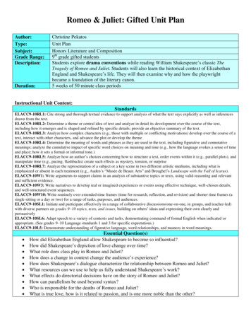
After completing this chapter, you will be able to:if Describe basic line conventions ./' Explain the concept of layers in a CADD drawing.if Describe how drawing layers are used in various drafting fields ./' Create and manage layers.if Use DesignCenter to copy layers and linetypes between draw'in",.AutoCAD has a layer system that allows you to organize and assign several properties to objects. Layers help you conform to drawing standards and conventions andcreate various displays, views, and sheets. This chapter introduces line conventionsand the AutoCAD layer system. It also introduces DesignCenter as a tool for reusingdrawing content.Drafting is a graphic language that uses lines, symbols, and text to describe howto manufacture or construct a product. Line conventions provide a way to classify thecontent of a drawing to enhance readability. Layers allow you to apply line conventions while drawing with AutoCAD. Use line conventions as a guide to develop layers.The ASME Y14.2 standard, Line Conventions and Lettering, recommends two linethicknesses to establish contrasting lines: lines are thick or thin. Thick lines are twiceas thick as thin lines. The recommended thicknesses are 0.6 mm for thick lines and0.3 mm for thin lines.3··1 describes common linetypes.shows anexample of a drawing with several common linetypes.The US National CAD Standard (NCS) recommends specific line thicknesses andcharacteristics for architectural and similar drawings. Thicknesses range from extrafine at 0.13 mm to 4X at 2 mm. Use the range of NCS-recommended line thicknesses toprovide accents to drawings as needed. A common practice is to select a few of the line-;·3.thicknesses that correlate best to specific applications. Seelayers: Componentsof the AutoCADoverlay systemthat allow you toseparate objectsinto logical groupsfor formatting anddisplay purposes.line conventions:Standards related toline thickness, type,and purpose.151
Figure 5--U.Line conventions adapted from ASME Y14.2, Line Conventions and Lettering. Line characteristicsand spacing are measured at full scale. Specifications vary according to drawing size.for line ofsymmetryand Continuousfor symmetrysymbol(Cont.J152AutoCAD and Its Applications-Basics
or uniquetreatment for asurface.Thick (0.6 mm). Consistsof one .l25" (3 mm) dashalternating with one .75"to IS' (19 mm to 38 mm)dash. A .06" (1.5 mm) spacethe dashes.Thin (0.3 nun), usuallysolid. Begins .06" (1.5 mm)from an object and extends.l25" (3 nun) beyond thelast dimension line. See16.Thin (0.3 mm), usuallysolid. See Chapter 16.Thin (0.3 mm), solid. SeeChapter 16.location andviewingdireclion·of aThick (0.6 mm). SeeChapter 23.Thick (0.6 mm). SeeChapter 8.viewingdirection of aShow whereaportion ofan object hasbeen removedfor clarity orPHANTOM,Continuous,or DASHEDContinuous,or DASHEDThin (0.3 mm) for longlines and thick (0.6 nun)for short break lines, solid.Break representation isbased on object or material. broken.Thin (0.3 mm), dashedor .01" (0.3 mm) diameterdots.Chapter 5 Line Standards and Layers153
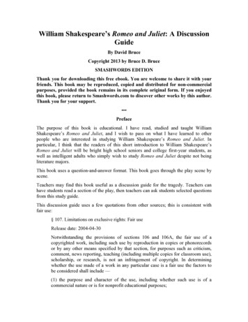
Figure 5-2.An example of a mechanical assembly drawing with several common types of lines.DinwI1sion lineI Phantom lint'1 - - - - - 2.300 --'-----I"---Extension 1i nl' . .lineCenterline -- lX .fedtuf(-;:;).----. t.cil(il'f line12 P SPUR GEAR12 TEETHOD .670Chain lineCenterlineCenterlineVIEW B-BofSECTION A-AFigure 5-3.Common US National CAD Standard line thicknesses.Majorobject lines at,ele'viltiorle(lg ,g, cIl1tting;cpl.anelines, Shott breaktitle text, minortitleand border lines.Extra wide, 0.7 mm154Major title underlines, schedule outlines, large titles, specialemphasis object lines, elevation and section grade lines, propertylines, sheet borders, and schedule borders.AutoCAD and Its ApplicationsBasics
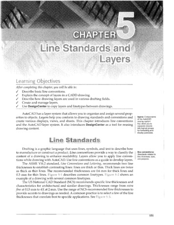
FigureThe Layer P'''perties Manager. Layer 0 is the default layer. Pick an icon to change thecorresponding layer setting.D;rouCi -fi lt(\----------,,,-prEll'-ildtU:-1purge: To removeunused items, suchas block definitionsand layers, from thedrawing.lineThe default 0 layer is the only required layer in an AutoCAD drawing. You cannotdelete, rename, or purge the 0 layer. However, the 0 layer is primarily reserved fordrawing blocks, as described later in this textbook. Draw each object on a layer specificto the object. For example, draw object lines on an Object layer, draw floor plan wallson an A-WALL layer, and draw construction lines on a Construction or A-ANNO-NPLTlayer. Make a conscious effort to assign appropriate layers to objects.Add layers to a drawing to meet the needs of the drawing project. Use the LayerProperties Manager to add a new layer. Select an existing layer with properties similarto those you want to assign to the new layer. Reference the 0 layer to create the firstnew layer using a default template. Then pick the New Layer button, right-click in thelist view and select New Layer, or press [Alt] [N]. A new layer appears, using a defaultname. The layer name is highlighted, allowing you to type a new name. See Figure 5-5.Pick away from the layer in the list or press [Enter] to accept the layer.Layer NamesName layers to reflect drawing content. Layer names can include letters, numbers,and certain other characters, including spaces. Layer names are usually set according5-6 provides examples of typicalto specific industry or company standards.mechanical, architectural, civil, and electronic drafting layer names.Figure 5-5,AutoCAD names a new layer Layern by default and provides the opportunity for you tochange the name immediately.Fdit156AutoeAD and Its Applications-Basics
toIn AutoCAD, you can use an overlay system of layers to separate different objectsand elements of a drawing. For example, you might choose to draw all visible objectlines on an Object layer and all dimension objects on a Dimension layer. You can displayboth layers to show the complete drawing with dimensions or hide the Dimension layerto show only the visible objects. The following is a list of ways you can use layers toincrease productivity and add value to a drawing: Assign each layer a different color, linetype, and lineweight to correspond toline conventions and to help improve clarity. Make changes to layer properties to update all objects drawn on the layer. Turn off or freeze selected layers to decrease the amount of informationdisplayed on-screen or to speed up screen regeneration. Plot each layer in a different color, linetype, or lineweight, or set a layer not to plot.o Use separate layers to group specific information. For example, draw a floorplan using floor plan layers, an electrical plan using electrical layers, and aplumbing plan using plumbing layers.e Create several sheets from the same drawing file by controlling layer visibilityto separate or combine drawing information. For example, use layers to displaya floor plan and electrical plan together to send to an electrical contractor or todisplay a floor plan and plumbing plan together to send to a plumbing contractor.overlay system:A system ofseparating drawingcomponents bylayer.The type of drawing typically determines the function of each layer. In mechanical drafting, you usually assign a specific layer to each different type of line or object.For example, draw object lines on an Object layer that is black in color, has a solid(Continuous) linetype, and is 0.6 mm wide. Draw hidden lines on a green Hidden layerthat uses a 0.3 mm hidden (HIDDEN or DASHED) linetype.Architectural and civil drawings may require hundreds of layers, each used toproduce a specific item. For example, draw full-height floor plan walls on a blackA-WALL-FULL layer that has a 0.5 mm solid (Continuous) linetype. Add plumbing fixturesto a floor plan on a blue P-FLOR-FIXT layer that has a 0.35 mm solid (Continuous) linetype.You can create layers for any type of drawing: detail parts, assemblies, floor plans,foundation plans, partition layouts, plumbing systems, electrical systems, structuralsystems, roof drainage systems, reflected ceiling systems, HVAC systems, site plans,profiles, topographic maps, and details. Interior designers may use floor plan, interiorpartition, and furniture layers. Electronics drafters may draw each level of a circuit onits own layer.Use the LAYER command to open the Layer Properties Manager, where you cancreate and control layers. See5-4. The columns in the list view pane on the rightside of the Layer Properties Manager list layers and provide layer property controls.Properties in each column appear as an icon or as an icon and a name. Pick a propertyto change the corresponding layer setting. The tree view pane on the left side of thelayer Properties Manager displays filters for limiting the number of layers displayedin the list view pane.Chapter 5Line Standards and Layers"l1liII1IIl1liII1II ffi -'155
Examples of typicallayer names incommon CouplingHowever, simple or generic drawings may use a more basic naming system. Forexample, the name Continuous-White indicates a layer assigned a continuous linetypeand white color. The name Object-? identifies a layer for drawing object lines, assignedcolor 7. Another option is to assign the linetype a numerical value. For example, nameobject lines 1, hidden lines 2, and centerlines 3. If you use this method, keep a writtenrecord of the numbering system for reference.More complex layer names are appropriate for some applications, and may includeitems such as drawing number, color code, and layer content. For example, the nameDwg100-2-Dimen refers to drawing DWG100, color 2, for use when adding dimensions.The American Institute of Architects (AlA) CAD Layer Guidelines, associated with the USNational CAD Standard, specifies a layer naming system for architectural and relateddrawings. The system uses a highly detailed layer naming process that assigns eachlayer a discipline designator and major group and, if necessary, one or two minor groupsand a status field. The AlA system allows complete identification of drawing content.Layer names are listed alphanumerically as you create new layers. See5-7.Pick any column heading in the list view to sort layer names in ascending or descendingorder according to that column. The layer Properties Manager is a palette, so newlayers and changes made to existing layers are immediately applied to the drawing.There is no need to "apply" changes or close the palette to see the effects of the layerchanges in the drawing.TIPTo accelerate the process creating multiple layers, press the corn1l1lakey L] after typing each layer name to create another new layer.5 -'7.Layer names are automatically listed in alphanumeric order when you create new layers orchange layer names.Na{ "',,"::2"'!iJ AII ccllc;'::::·.c -:'-"'a. All Used Layer,211o'Center 7 7,; ,Free,e'""; '- ;'(i"" " ;,, o ::,, itS' ! -0:.·61-E7 7 7On·21-J7 7A-.r .p:.;;;.:6.: .Chapter 5 Line Standards and LayersnfTIfofITfdf'ITfdf'ITfIillwhi!:e Continuous I!iIIl white COI1tinUOll5 II!!! white Continuoll5 1\1 whrc COl1ti u(}u5 III white Continuous II!II white Continuous IIIIl white C()ntinuous III whit Continuous -;ranspanmcDef lult 0Def lult 0Def lult 0Default ()Def.lult 0Def.lult 0Default DDefault 0y: I' YI " " ,, :W VPF,"",,,.,,,COlor 7C('or 7Coior 7Cobrj(.,:,;m "O;;JmjCciDrj(cwrj,.,,'t"';' .,(tl e@ 157
Renaming LayersTo change a layer name using !he Layer Properties Manager, slowly double-clickon the existing name in the Name column to highlight it. Type the new name and press[Enter] or pick outside of the text box. You can also rename a layer by picking the nameonce to highlight it and then pressing [F2], or by right-clicking and selecting RenameLayer. You cannot rename layer 0 or layers associated with an external reference.Exercise 5-1Complete the exercise on the companion website.www.g-wlearning.com/CADSelecting Multiple LayersSelect multiple layers to speed the process of deleting or applying !he same properties to several layers. Use standard selection practices or !he shortcut menu to selectmultiple layers. Hold [Shift] to select several consecutive layers, or hold [Ctrl] to selectseveral nonconsecutive layers. You can also use a window to select all the layers thatcontact the window. The following selection options are available when you right-clickin the list view: Select All. Selects all layers. Clear All. Deselects all layers. Select All but Current. Selects all layers except the current layer. Invert Selection. Deselects all selected layers and selects all deselected layers.Exercise 5-2Complete the exercise on !he companion website.www.g-wlearning.com/CADLayerThe icon in the Status column describes !he status, or use, of a layer. A green checkmark indicates the current layer. The status line at the top of the Layer PropertiesCurren! Manager also identifies the current layer.A gray sheet of paper, or Not In Use icon, in the Status column indicates a noncurrent layer that is not used by the drawing. A blue sheet of paper, or In Use icon, inNo! in Use the Status column means the layer is assigned to objects, but the layer is not current.The In Use icon also means that you cannot delete or purge the layer, even if no objectsare assigned to the layer.In Usecurrent layer:The active layer.Whatever you drawis placed on thecurrent layer.Current LayerTo set a layer current using the Layer Properties Manager, double-click the layername, pick the layer name and select the Set Current button, or right-click on the layerand choose Set current. You can also make a layer current without using the LayerProperties Manager by picking the layer name from the Layer Control drop-down list158AutoCAD and Its Applications-Basics
in the layers panel of the Home ribbon tab. See3 8. Use the vertical scroll barto move up and down through a long list. The layer Control drop down list is a veryeffective way to activate and manage layers while drawing.Command line content search offers another way to find a layer and make a layercurrent without using the layer Properties Manager. Begin typing the letters in a layer IAutoCADname on the command line. Layers that match the letters you enler appear in the NEWsuggestion list as you type. Figureshows the results oftyping LITE atthe commandline to locate layers used to draw lighting symbols in an architectural drawing. Youmay need to search through the content category in the suggestion list to find thedesired layer. Select a layer from the suggestion list to set current.or the layer ControlYou can use the layer Propertiesdown list to change the current layer or layer properties while a mrnn1 r,cIis active. For example, draw aline segment using the current layer,and then, without exiting the LINE command, make a different layercurrent to draw the next lineon a differentTIPTo assign a different layer to existing objects, select the objects andthen choose the layer using the layer Properties Manager or the Layerlist.ControlPigtHl2 .5 B,MThe layer Controldrop-down listallows you to changethe current layer andadjust specific layerproperties.CUlTvnt-P.:- rnrIII CONSTRUCTION\} ·11· III CUTTINGQ -f!.- aT III DefpointsQ -o.:-!if' III DIMENSIONQ -l):- oi" III HIDDENQ - .- of III OBJECTG .J:;J:o of' III PHANTOMIJ.Q:. or III SECTIONIll): oi" III SHEETQl):- oi" I!II TEXTiV .f . uT L3 VIEWPORTFigUfl'? 5-9"Using commandline content searchto locate layers andset a specific layercurrent.Lu d i l C'UITl'l.i.tConjpntGli:cgoryChapter 5 Line Standards and Layers159
ExerciseComplete the exercise on the companion website.www.g-wlearning.com/CADYou can assign a unique color to each layer to help distinguish objects on-screen.You can also use layer colors to plot a drawing in color or to control object properties. Although plotting in color and controlling object properties using color are notcommon, assigning colors to layers is very important for on-screen drawing clarity,organization, workability, and format. Layer colors should highlight important featuresand symbols and not cause eyestrain.Use the Color column of the Layer Properties Manager to assign a color to each layer.Pick the existing color swatch to change the color using the Select Color dialog box.See Figure 5-10. The Select Color dialog box includes an Index Color tab, a True Colortab, and a Color Books tab. Each tab provides a different method for color selection.The default Index Color tab provides enough color options for most 2D drawings.The Index Color tab includes 255 color swatches, each numerically coded according tothe AutoCAD Color Index (ACI). The first seven colors in the ACI have both a numberand a name: 1 red, 2 yellow, 3 green, 4 cyan, 5 blue, 6 magenta, and 7 white.The color white (number 7) appears white on the default dark-gray model space background. It appears black on the default white layout background.Hover over a color swatch to display the code in the Index color: field and the mixof red, green, and blue (RGB) used to create the color in the Red, Green, Blue: field.Pick a color swatch to select and display the color in the Color: text box, or type thecolor name or ACI number in the Color: text box. A preview of the color selection and asample of the previously assigned color appear in the lower-right corner of the dialog box.After you select a color, pick the OK button to assign the color to the specifiedlayer. The layer color swatch indicates the color. By default, all objects are displayed inthe selected layer color, or ByLayer.absolute value: Inproperty settings. avalue setinsteadof directlyreferencedby layer or by block.An absolute valuecoloI'w;sil n'3(:ftoa la)'er w,ith()1.llaccesSing theL""' J: -.: ; .i.""' .i.""' .i.'"" .: '"" .: ,,""' ' '"" .: , ., ""' '"" .:'"" .:Joverrides thecorresponding il.Jilt i:lVL1,f\lel',,,e:ltir'ga:nd use m160y , andthe:LaYerAutoCAD and Its Applications-Basics
FjgufeUse the Select Colordialog box to assigna color to a layer.':';lill'1(Lmlj'l L- qCI.-'J!( lr:'icui()r indo:selectL'llcolormnnJ:-wrComplete the exercise on the companion website.www.g-wlearning.com/CADAppropriate linetypes and line thicknesses enhance the readability of a drawing.You can apply standard line conventions to objects by assigning a linetype and thickness to each layer. AutoCAD provides standard linetypes that match or are similar toASME, ISO, NCS, and other standard linetypes. You can also create custom linetypes.Assign lineweights to layers to achieve different line thicknesses.Use the linetype column of the layer Properties Manager to assign a linetype toeach layer. Pick the existing linetype to change the linetype using the Select linelypedialog box. See5-11. By default, the Continuous linetype is the only linetypein the loaded linelypes list. Use the Continuous linetype to draw solid lines with nobreaks.Loading LinetypesAutoCAD maintains linetypes in external linetype definition files. Before youcan apply a linetype other than Continuous to a layer, you must load the linetype intothe Select linelype dialog box. Pick the load . button to display the load or ReloadFigure 5-11.The Select Linelypedialog box allowsyou to load linetypes'oodod!1'"""""e.,'",A"",,"co .IDeSCriptionfor use in the currentdrawing.rj (1)fIOiHkd /Pi.ck to 10,'1(1""ny I,'",--, . OKChapter 5 Line Standards and Layers. 1 0 11 01,··Hdp, : id ltiona1.,.1161
Linetypes dialog box. See5-12. The acad.lin or acadiso.lin file is active, dependingon the template you use to begin the drawing. The acad. lin and acadiso.lin files are identical except that the acadiso.lin file applies a 25.4 scale factor to non-ISO linetypes toconvert inches to millimeters for metric drawings. Pick the File . button and use theSelect Linetype File dialog box to select a different linetype definition file.The Available Linetypes list displays the name and a description and image ofeach linetype available from the active linetype definition file. Use the scroll bar toview all available linetypes, and use the image in the Description column to aid inselecting the appropriate linetypes to load. Choose a single linetype, or select multiplelinetypes using standard selection practices or the shortcut menu. Pick the OK buttonto return to the Select Linetype dialog box, where the linetypes you selected nowappear. See5-13. In the Select Linetype dialog box, pick the linetype to assignto the layer, and then pick the OK button.5-14 shows the HIDDEN linetypeselected in5-13 assigned to the layer named Hidden.figure 5-12.The Load or ReloadLinetypes dialog boxdisplays linetypesavailable for e storedSelectISOdashspacBISOlong-dashdot , .ISO long-dash doubI8-dotISO long-dash lIipl8-dot 'ISO dot .ISO lortg-dash short-dash .;ISO IOl1g-dash double-shOll-dash ,ISO dash dotISOdouble-dashdotfigure 5-13.Linetypes loadedinto the drawingusing the Load orReload Linetypesdialog box appearin the Loadedlinelypes list.162AutoCAD and Its Applications-Basics
F igurcObjects drawn on the Hidden layer will have the HIDDEN linetype.: Sedrch for layerl!iJPII'II! 'Nlfll:eColu fIIiiI whiteiii! w-hiteill!! whiteColmjII whIteCDbl 7Coml 1CciorjComplete the exercise on the companion website.www.g-wlearning.com/CADSetting Linetype ScaleYou can change the linetype scale to adjust the lengths of dashes and spaces inlinetypes to make a drawing more closely match standard drafting practices. Changingthe globallinetype scale is the preferred method for adjusting linetype scale, but it ispossible to change the linetype scale of specific objects.Use the lTSCAlE system variable to make a global change to the linetype scale.Enter LTS or LTSCALE at the keyboard and then enter a new value. The default globallinetype scale factor is 1. A value less than 1 makes dashes and spaces smaller, and avalue greater than 1 makes them larger. See.5··] 5. After you enter a value andpress [Enter], the drawing regenerates and the global linetype scale changes for alllines on the drawing. Experiment with different linetype scales until you achieve thedesired results.linetype scale: Thelengths of dashesand spaces inlinetypes.globallinetypescale: A linetypescale applied toevery linetype in thecurrent drawing.Be careful when changing linetype scales to avoid making yourdrawing look odd and not in accordance with drafting standards.fi gure 5-15.The CENTERlinetype at differentlinetype scales.1.01.5Chapter 5 Line Standards and Layers163
ulnglineweight: Theassigned width oflines for display andplotting.LayerAssign a lineweight to a layer to manage the weight, or thickness, of objects.You can adjust the lineweight to match ASME, ISO, NCS, or other standards. Use theLineweight column of the Layer Properties Manager to assign lineweight to each layer.Pick the existing lineweight to change the lineweight using the Lineweight dialog box.See Figure 5-Hi. The Lineweight dialog box displays fixed AutoCAD lineweights. Scrollthrough the Lineweights: list and select the lineweight to assign to the layer. Pick theOK button to apply the lineweight and return to the Layer Properties Manager.Lineweight SettingsThe LlNEWEIGHT command provides access to the Lineweight Settings dialogbox, shown in5-17. Use the Units lor Listing area to set the lineweight thicknessto Millimeters (mm) or Inches (in). The units apply only to values in the Lineweight andLineweight Settings dialog boxes, helping you to select lineweights based on a knownunit of measurement.Check the Display Lineweight box to display object lineweight on-screen. Usethe Adjust Display Scale slider to adjust the lineweight display scale to improve theappearance of lineweights when lineweight display is on. When lineweight display isoff, all objects display a 0, or one-pixel, thickness regardless of the lineweight assignedto the layer. You can also toggle screen lineweight on and off using the Show/HideLineweight button on the status bar.The Default drop-down list sets the value used when you assign the Default lineweight to a layer. The Default lineweight is an application setting and applies to anydrawing you open. It is not template-specific and remains set until you change the value.figure 5-16.Use the Lineweighldialog box to assigna lineweight to alayer.Lilleweights:SeleclUnp\veight '"., .hmn'iist0.05 mm0.09 mm0.13mm0.15mmO.18mm0.20 mm0.25 mm0.30 mm0.35 mmOrigil1a1: Derault ,New:Default164AutoCAD and Its Applications-Basics
Unit for li ting@i-!iillimeters(mm) (:) Inches (in) /:E!:3,Qisplay Lineweight - Dela\-llt, Adjust Display SC lle, MinCUrrer!! Lineweight BywyerDo not assign the Default lineweight to layers if you anticipate using a different defaultlineweight for different drawing applications. Assign a specific lineweight, other thanDefault, to each layer to maintain flexibility and consistency between drawings.Y01,lcan use the Lineweights list in the Lineweight Settings dialog boxto set an absolute value for lineweight. If you set the absolute lineweight to 0.30 mm, for example, the 0.30 mm. lineweight overrides theliheweights assigned to layers and all objects appear 0.30 mm thick.For mostset lineweight to ByLayer and use layers and theM"n"" ., to controlComplete the exercise on the companion website.www.g-wlearning.com/CADASME standards recommend that all objects be opaque and dark for most applications. However, you can choose to draw transparent, or see-through, objects for specificdrawing requirements, usually for architectural, civil, or technical illustration applications. For example, draw an existing building using transparent objects to highlight aproposed structure drawn using nontransparent objects.Setting TransparencyUse the Transparency column of the Layer Properties Manager to assign a level oftransparency to each layer. Pick the existing transparency value to change the level oftransparency using the Layer Transparency dialog box. See5-1S. Type a valuebetween a and 90 or select a value from the drop-down list.U e the layerTransparency dialogbox to assign a levelof transparency to alayer.trdlbparC'l1CYVilhwclnr t'L('cl\"illw' (rom th·li:,;!-Chapter 5Line Standards and Layers165
The default layer transparency value of 0 creates nontransparent objects, appropriate for most layers. A higher transparency value increases transparency. Any objectdrawn on a transparent layer appears transparent. One type of object that is commonlymade transparent is a hatch, which fills an area with a pattern, solid, or gradient. See'"'''''' 5-19. Chapter 23 explains creating hatch objects.Showing and Hiding TransparencyShow or hide transparency using the Show/Hide Transparency button on thestatus bar. Transparency is on by default, and all objects drawn using a transparentlayer appear at their transparent level. Disabling transparency using the Show/HideTransparency button makes all transparent objects appear nontransparent, but doesnot change the layer transparency property.Byl.aYEW (Uld u:sel.aye:fSc lind the LayerFigure 5·19.An example of a portion of a storm water pollution control plan with transparent solid hatchobjects that represent different impervious and non-impervious surfaces.166AutoCAD and Its Applications-Basics
Use the Plot Style column of the layer Properties Manager to assign a named plotstyle to each layer. AutoCAD uses color-dependent plot styles by default, so the plotstyle property is disabled. This textbook explains plot styles when appropriate.Use the Plot column of the layer Properties Manager to disable a layer fromprinting or plotting. Pick the printer, or Plot, icon to change it to the 1110 Plot icon if thelayer should not plot. The layer displays on-screen and is selectable, but does not plot.Plot No PlotUse the Description column of the layer Properties Manager to describe eachlayer. To add or change a description, slowly double-click on the blank area or existingdescription, type a description, and press [Enter] or pick outside of the Description textbox. Another method is to right-click and select Change Description.Use the On column of the layer Properties Manager to turn a layer on or off. Thelit light bulb, or On icon, indicates that the layer is turned on. Objects assigned to an"on" layer display on-screen and can be selected, regenerated, and plotted. Pick thelit light bulb to turn the layer off, indicated by the gray light bulb, or Off icon. Objectsassigned to an "off" layer do not display on-screen and do not plot. You can select andedit objects that are off using advanced selection techniques. Objects that are off canalso be regenerated.OnOffTurn layers on orusing the layer Control drop-down list in thelayers panel of the Home ribbon tab.Use the Freeze column of the layer Properties Manager to freeze or thaw a layer.The sun, or Thaw icon, indicates a thawed layer. Objects assigned to a thawed layerdisplay on-screen and can be selected, regenerated, and plotted. Pick the sun to freeze Freeze Thawthe layer, indicated by the snowflake, or Freeze icon. Objects assigned to a frozen layerdo not display on-screen, and cannot be plotted or regenerated. You cannot select oredit objects that are frozen. Freeze layers to hide objects and ensure that you do notaccidentally modify the objects.Use the lIIew VI" Freeze column to control thawing or freezing of layers when youcreate a new viewport. Additional layer functions also apply to layouts and viewports.This textbook explains layouts and viewports when appropriate.VI' Freeze-Q.You can also freeze or thawlayersusiIlg the layer ContrOl dropcdownlist in the layers panel of the Home ribbon tab. You cannot freeze thecurrentor make a frozencurrent.Chapter 5 Line Standards and LayersVI'Thaw167
Use the Lock column of the Lay
The ASME Y14.2 standard, Line Conventions and Lettering, recommends two line thicknesses to establish contrasting lines: lines are thick or thin. Thick lines are twice as thick as thin lines. The recommended thicknesses are 0.6 mm for thick lines and 0.3 mm