Transcription
DWDM Fundamentals, Components,and Applications
DWDM Fundamentals, Components,and ApplicationsJean-Pierre LaudeArtech HouseBoston Londonwww.artechhouse.com
Library of Congress Cataloging-in-Publication DataLaude, Jean-Pierre.DWDM fundamentals, components, and applications / Jean-Pierre Laude.p. cm. (Artech House optoelectronics library)Includes bibliographical references and index.ISBN 1-58053-177-6 (alk. paper)1. Wavelength division multiplexing.2. Optical communications.3. Light Wavelength.I. Title.II. Series.TK5103.592.W38 L38 2002621.382 7 dc212001055246British Library Cataloguing in Publication DataLaude, J. P. (Jean-Pierre)DWDM fundamentals, components, and applications. (ArtechHouse optoelectronics library)1. Optical communications2. MultiplexingI. Title621.3 827ISBN 1-58053-177-6Cover design by Gary Ragaglia 2002 ARTECH HOUSE, INC.685 Canton StreetNorwood, MA 02062All rights reserved. Printed and bound in the United States of America. No part of this bookmay be reproduced or utilized in any form or by any means, electronic or mechanical, including photocopying, recording, or by any information storage and retrieval system, without permission in writing from the publisher.All terms mentioned in this book that are known to be trademarks or service marks havebeen appropriately capitalized. Artech House cannot attest to the accuracy of this information. Use of a term in this book should not be regarded as affecting the validity of any trademark or service mark.International Standard Book Number: 1-58053-177-6Library of Congress Catalog Card Number: 200105524610 9 8 7 6 5 4 3 2 1
2Basic Principles and Background32.1Wavelength Division Multiplexing: Basic Principles32.2History of WDM in a Few Words42.3WDM and Time Division Multiplexing42.4Wavelength Domain and Separation Between Channels 52.5Wavelength Allocation72.6Optical Wavelength/Optical Frequency Conversion72.7How Many Channels?102.8Some Definitions11v
viDWDM Fundamentals, Components, and .9.22.9.32.9.42.9.5SolitonsSoliton PropagationWDM of SolitonsFrequency-Guiding FilteringDispersion-Managed SolitonsConclusion121213151516References163Dense WDM and Demultiplexers193.13.1.1Passive Components: The Current Available ChoiceDense WDMs Are Making Optical NetworkDesign PracticalDWDM Component lier ResearchPrinciples of AWGDispersionFree-Spectral RangeFree Spatial Range and the Number of AvailableChannelsPolarization DependencyThermal DriftTypical ValuesTechnical State of the Art24242526263.33.3.13.3.23.3.33.3.4FBGPeriodic Modulation of Index in the Fiber CoreMain Properties of FBGDifferent Types of Bragg GratingsDrift with .2.51920
Contentsvii3.3.5Typical Specifications of Available Bragg GratingDWDM313.43.4.13.4.23.4.3Optical Multidielectric FiltersGeneral PrinciplesMaterials and Processes for Enhanced PerformancesPractical Narrow Bandpass Filters n GratingsIntroductionEfficiency Versus WavelengthBandwidth of Grating DevicesGrating Micro-Optic DevicesThermal Drift of Grating Micro-Optic Devices3838414859633.6Cascaded Mach-Zehnder Interferometers643.7Other Devices: FBG/MZ Interferometer Devices673.83.8.13.8.2Methods for Broadening and Flattening the SpectralShape of the Transmission Channels of Grating WDM 68Introduction68Principle693.8.33.8.4Experimental ExampleConclusion72723.93.9.13.9.23.9.3Comparison of the Different SolutionsSome RemarksDevice Polarization SensitivityConclusion74747575References774Sources and Wavelength Converters for DWDM834.1Introduction83
viiiDWDM Fundamentals, Components, and Applications4.2Semiconductor Lasers844.2.1Laser Material844.2.2Quantum Well Lasers854.2.3Quantum Dot Lasers854.2.4Edge-Emitting Semiconductor Lasers864.2.5Vertical-Cavity Surface Emitting Lasers924.2.6Wavelength Tunability in Semiconductor Lasers944.3Glass-Doped-Based Lasers with Narrow Line-Widths964.3.1Principle964.3.2Fiber-Based Short-Pulse Laser Sources974.4Spectral Slicing of Sources984.4.1Principle984.4.2Typical Examples984.4.3Calculation of Spectral Filtering Losses1014.4.4Calculation of the Spectral Filtering Losses of RealSystems1024.4.5Combining Spectral Slicing and TDM1044.4.6SC Lightwave Optical Sources: Coherent Sources forSpectrum Slicing WDM1044.4.7Comparison of Different Technologies1064.5Wavelength ic 6Difference Frequency Generation1124.5.7State of the Art in Wavelength Conversion in 2001113References113
Contentsix5WDM and Optical .35.2.4SOAsIntroductionFP Type AmplifiersTWAsModern Devices1251251261271275.3Brillouin Scattering Amplifiers1285.4Raman Scattering Amplifiers1285.55.5.15.5.25.5.35.5.4Rare Earth-Doped Fiber Optic AmplifiersIntroductionFundamentals of EDFAsGain BandHistorical Notes on Amplification in WDMTransmissionAdvantages and Drawbacks of EDFAs129129129132134135Optical Signal-to-Noise Ratio of Erbium-DopedFiber and Hybrid Raman/Erbium-Doped FiberAmplifier Transmissions1365.7Erbium-Doped Planar Waveguides1395.8Distributed Optical Amplification1405.9Comparison of Some Typical Characteristics of theMain Optical Amplifiers140References1416Routers, Cross-Connects, and Add/Drops1476.1Introduction1475.5.55.6
xDWDM Fundamentals, Components, and Applications6.1.16.1.26.1.3Connections in WDM NetworksTopological ConfigurationsAn Industrial Point of View on IP TransportNetworksSwitching, Routing, and Processing of Signals in theOptical Domain1471486.26.2.16.2.2Wavelength ConversionIntroductionInfluence of Wavelength Conversion on 3.5Network Architecture ClassificationBroadcast and Select NetworksWavelength Routed NetworksLinear Lightwave NetworksLogically Routed NetworkMultigranularity Cross-Connect Architecture1541551551551551566.4Some Definitions Used for InterconnectionPerformance CharacterizationBandwidth, Effective Bandwidth, AggregateBandwidthSignaling 576.5Interoperability in Optical Routed DWDMNetworks1586.66.6.16.6.26.6.3Space SwitchesCrossbar SwitchesRouters/Selectors Switches and Benes SwitchesEnabling Technologies1581591591616.76.7.1Passive Wavelength RouterNode with Interconnected Demultiplexer/Multiplexers169169
Contentsxi6.7.2Static Grating Routers1726.86.8.16.8.26.8.3Optical Cross-ConnectorWSXCCross-Connect with Wavelength ConversionLayered-Switch .56.9.66.9.76.9.8OADMsIntroductionOADM with FBGs and CirculatorsAcousto-Optic Add/DropAdd/Drop with AWGAdd/Drop with Free-Space Grating SolutionsTunability of OADMCascading of OADMOptical Time Division Multiplexing DM Limits Caused by Optical Nonlinearities inOptical .3.3XPMInterchannel XPMIntrachannel Cross-Phase ModulationNonlinear Channel Depolarization Through XPM2252252252267.47.4.17.4.2FWMInterchannel FWMIntrachannel FWM2272272307.5SBS231
xiiDWDM Fundamentals, Components, and l Note237References2378Application of DWDM to TelecommunicationNetworks2458.18.1.18.1.28.1.4Some of the Earlier ApplicationsIntroductionFirst Broadband Multiwavelength Passive OpticalNetworksOne of the First Access Networks Using aMultiwavelength Passive TreeSome of the Earlier DWDM Virtual Topologies2472478.28.2.18.2.28.2.38.2.48.2.5Today s DWDM NetworksIntroductionNetworks Topologies and Transfer ModesWDM for Optical Switching and RoutingEvolution Towards IP Over DWDMOptical Packet Switching2482482482502512518.3Long-Distance Transmission2548.4Other DWDM sion261References2628.1.39245245246
ContentsxiiiList of Acronyms263About the Author271Index273
PrefaceThis book is intended for people interested in the future of telephone, data,video, and Internet communication, and to graduate students, scientists,designers, development engineers, and technicians who want to learn moreabout dense wavelength division multiplexing (DWDM). The readersworking in the field of telecommunications, such as components and systemsdesigners, may find useful references along with the text. I hope this bookwill also be useful to scientists and engineers working in the field of optics,spectroscopy, optronics, electro-optics, and micro/nano technology whowould be willing to offer their expertise to solve some of the still-open problems in telecommunications. Conversely, this book may help them to applyto different fields some of the tremendous progress and investments alreadymade in the optical telecommunication field. Perhaps this book will be alsouseful to marketing managers who want to get information and prospects onthe future of optical networks.It is expected that the book will be mostly useful in understandingcomponents and principles used in existing and/or in next generations ofDWDM optical telecommunication networks. I began research on WDMcomponents more than 20 years ago in a company devoted to advanced optical instrumentation. I had the opportunity to participate in the WavelengthTime Division Multiplexing (WTDM) research group within the Researchand Development in Advanced Communication Technologies in Europe(RACE) program, and to the Wavelength-agile Optical Transport andAccess Network (WOTAN) and Switchless Optical Network for AdvancedTransport Architecture Advanced Communications Technologies andxv
xviDWDM Fundamentals, Components, and ApplicationsServices (SONATA) groups, within the Advanced Communications Technologies and Services (ACTS) program, in the field of DWDM. This was anideal platform to participate in the dreams and in the successes of many ofthe most important European telecommunication groups. As a consultant,I also had the opportunity to participate in the challenge of HighWaveOptical Technologies, a new company successfully exploiting the opportunities in the DWDM component and subsystem market.In 1993, I published my first book entitled Wavelength Division Multiplexing. Of course, accelerated research efforts within the international community have produced many new concepts and devices in the field. Thisbook could not be a revised edition of my first work. I had to analyze andsummarize many new developments, keeping only when necessary some ofthe basic material of the first work.
AcknowledgmentsI am grateful to Christine, my wife, for her love. Our children, JeanChristophe, Vincent, Thomas, Blandine, Marjolaine, and Grégoire, havebeen a great source of support and encouragement. They could understandwhy this book was so impossibly demanding, as most of them are involved inscience and technology. Dr. Vincent Laude deserves a special mention as heplayed an important role in the critical reading and correction of the entirebook. I would like to express my gratitude for his patience and readinessto help.xvii
1IntroductionSi possible je voudrais montrer des futurs désirables qui n ont pas encore étéimaginés à seule fin d ajouter de nouveaux buts. (If possible, I want to showdesirable prospects that have never been conceived for the sole purpose ofadding new aims.)Tom ShannonSpring 2000The long-awaited deployment of dense wavelength division multiplexing(DWDM) in long-haul networks is fast becoming a reality. In the access network DWDM becomes a serious option to accommodate increasing multimedia, broadband, and IP traffic.Fueled by the need for rapidly increasing volumes of information transfer, and by new requirements that are far less predictable than they have beenfor telephony, the development of optical fiber communication moves everforward. DWDM that corresponds to the superimposition of optical signalsat different wavelengths closely spaced at 100 GHz or less on each fiber,becomes, as a matter of fact, the unavoidable solution, not only for a capacityincrease at lower cost, but also for switching and routing in the opticaldomain.The optical add/drop multiplexer (OADM) and optical cross-connecttechnology are seen as a viable option in the large network optical nodes,when the digital cross-connectors are unable to scale to higher port-densityand higher speed interface requirements at affordable costs, or in general,1
2DWDM Fundamentals, Components, and Applicationswhen the optical/electrical/optical conversion would be unnecessary andquestionable.Today s telecommunications networks have benefited from research insymbiosis in the fields of materials, electromechanics, microelectronics, computing, and optics.Nowadays, low nonlinearity fibers, dispersion management on fibers,lasers with high wavelength stability over years, new tunable light sources,new erbium-doped amplifiers, distributed Raman amplifiers, semiconductoramplifiers and gates, wavelength converters, couplers, space-switches, andwavelength division multiplexers offer new solutions. DWDM with morethan 160 channels, OADM with more than 32 channels, and wavelengthselective cross-connects (WSXC) with 32 32 input-to-output ports are currently in commercial use. Wavelength-interchanging cross-connects (WIXC)will become available soon, as the first industrial tunable lasers and wavelength converters are already proposed on the market.We did our best to organize the text of this book into a logical sequenceof chapters. After the short introduction of this chapter, the basic principlesand background in wavelength division multiplexing are reviewed inChapter 2. Chapter 2 also includes an introduction to soliton multiplexing,one of the options for long-distance transmissions. In Chapter 3, we reviewthe current choices available in DWDM passive components. In Chapter 4we present the main active sources including semiconductors lasers, glassdoped lasers, broadband sources for spectral slicing, and the wavelength conversion technology. In Chapter 5 we review the different solutions in opticalamplification. Optical switches, routers, cross-connects, and add/drops aredescribed in Chapter 6, after discussions on topological configurations andarchitectures of optical networks in which they are utilized.In Chapter 7, the optical fiber nonlinearities limiting the performanceof DWDM systems are presented. Chapter 8 gives examples of applicationsof the DWDM technology and results in long-haul transmission networksand in different passive or wavelength-switched voice and data networksincluding the Internet.
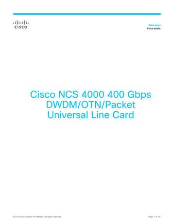
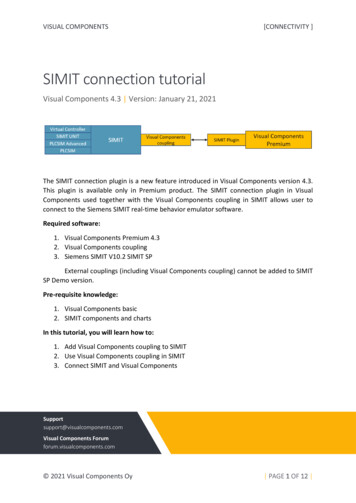
2Basic Principles and Background2.1 Wavelength Division Multiplexing: Basic PrinciplesTelecommunications makes wide use of optical techniques in which thecarrier wave belongs to the classical optical domain. The wave modulationallows transmission of analog or digital signals up to a few gigahertz or gigabits per second on a carrier of very high frequency, typically 186 to 196 THz.In fact, the bit rate can be increased further, using several carrier waves thatare propagating without significant interaction on the same fiber. It is obvious that each frequency corresponds to a different wavelength. This technique is called frequency division multiplexing (FDM) or wavelengthdivision multiplexing (WDM). The latter term is currently preferred in mostcases. DWDM is reserved for very close frequency spacing (typically less than100 GHz corresponding to 0.8 nm at wavelengths near 1.5 mm). The term frequency division multiplexing is used in a few cases, such as multiplexingwith optical frequency shift keying and coherent detection. But the terminology is not completely stabilized.With WDM, it is possible to couple sources emitting at different wavelengths l1, l2, lj, ln into the same optical fiber. After transmission onthe fiber, the l1, l2, ln signals can be separated towards different detectors at the fiber extremity (Figure 2.1). The component at the entrance mustinject the signals coming from the different sources into the fiber with minimum losses: This is the multiplexer. The component separating the wavelengths is the demultiplexer. A simple optical coupler may replace themultiplexer, but losses will increase. Obviously, when the light propagation3
4DWDM Fundamentals, Components, and Applicationsl1 l2 l 3 l i l jljljlil1l2l3lil3l2l1Figure 2.1 WDM.is reversed, the multiplexer becomes the demultiplexer, and the reverse is alsotrue. It is important to note, however, that the coupling efficiency is not necessarily preserved in reverse operation. For example, if the multiplexer usessingle-mode (SM) entrance fibers and a multimode output fiber, the coupling losses would be excessive in the reversed usage. Multiplexers designedwith identical input and output fibers are usually reversible. Simultaneousmultiplexing of input channels and demultiplexing of output channels canbe performed by the same component, the multi/demultiplexer.2.2 History of WDM in a Few WordsThe optical multiplexing concept is not new. To our knowledge, it datesback to at least 1958 [1, 2]. Perhaps we can say that the idea of sendingmultiple signals, as shown in Figure 2.1, was straightforward, as it was atransposition of techniques used in classical telecommunications with electronics signals. But the technical problems to be solved were very difficult,and it took experts a great deal of time to solve them. About 20 years later,the first practical components for multiplexing were proposed primarily inthe United States, Japan, and Europe. In 1977, the first grating-WDM passive component was developed by Tomlinson and Aumiller [3].2.3 WDM and Time Division MultiplexingIs it easier to multiplex the signal in the electronic domain time divisionmultiplexing (TDM), or in the optical domain (FDM or WDM)? The
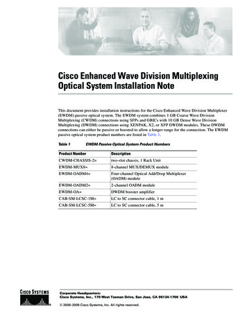
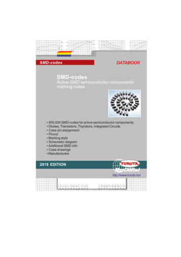
Basic Principles and Background5answer to this question is not easy and the optimum solution is generallyfound in the association of the different techniques.For low bit-rate services ( 2 Mbps), it is generally better to use onlyTDM techniques. For uncompressed, high-definition television (HDTV)broadcasting, WDM is highly recommended. The video compression techniques minimize the bandwidth requirement. However, at the time of thiswriting, CATV and HDTV still require 4 Mbps and 25 Mbps, respectively.Applications such as video networks linking workstations, television studiocenter signal routing systems, video conference networks, interactive videotraining systems, bank information service networks, and data-transfer networks between computers, integrated service digital networks (ISDN), teledistribution, and generally all broadband networks increasingly use bothtime and wavelength multiplexed optical lines. Today, the predicted demandper subscriber in 2010 is on the order of 100 Mbps. That will not be possiblewithout the deployment of DWDM optical fiber networks.It is understood that a practical network is very often made up of anassociation of architectures that constitute the physical medium of the network between stations. The topology is called virtual when it is concernedonly with logical connections between stations. One example of an opticalmultiplexing application is to create virtual topologies on request. The network configuration can be modified independently of its physical topologyby changing the emitted or received optical frequencies. In these architectures WDM cross-connectors, WDM routers, and WDM add/drops becomemore and more important.2.4 Wavelength Domain and Separation Between ChannelsWith modern, commercially available telecommunication fibers, it is possible to transmit information over a large spectral range (Figure 2.2) with twodomains with low attenuation, one around 1.3 mm and another around1.55 mm. Between these two domains there is generally a high attenuationat 1.39 mm due to the residual OH radical in the fiber. SM silica fibers withminimum loss of about 0.16 dB/km at 1.55 mm are available. Losses 0.4dB/Km at 1.5 mm and 0.5 dB/Km at 1.31 mm are specified in the ITU-TG.652 recommendations. In medium- and long-distance DWDM transmissions, SM fibers are generally used in the domain 1,520 to 1,620 nm (seeparagraph 5), due to the availability of efficient optical amplifiers andsources.
6DWDM Fundamentals, Components, and ApplicationsdB/km1.91.390.6 mm105Absorption peak of OHWithout OH150300THznFigure 2.2 Typical loss of a low OH content fiber.For applications such as metropolitan area networks, special SM fiberswith very low OH content are commercialized. They can be used from 1,335to 1,625 nm (for instance, AllWave fiber from Lucent Technologies).On multimode silica vapor phase axial deposition (VAD) fiber withoutOH impurity, losses lower than 4 dB on 2.4 km were obtained from 0.65 to1.9 mm as long ago as 1982 [4].On multimode fibers, a graded index design allows a temporal dispersion minimization, but the optimum profile depends greatly on wavelengthand material, and the dispersion varies with wavelength.The separation between channels is now 0.8 nm or more on mostof the installed networks using WDM. International TelecommunicationUnion (ITU) standardization proposes a frequency grid with separations of100 GHz (about 0.8 nm) with multiples and submultiples. Now the published minimum channel spacing is about 0.1 nm. However, at the beginning of the twenty-first century, nothing lower than 0.2-nm (25 GHz)spacing was commercially available. At first glance, a fiber without OHwould allow 1,000 channels at 50-GHz spacing to be multiplexed over itslarge spectral range!Of course there are some limitations of WDM (Figure 2.3). The mainproblem is crosstalk (parasitic light) coming from technical defects in thedemultiplexers, but also from physical problems such as wavelength conversion along the transmission fiber by four-wave mixing, Brillouin or Ramaneffect, or other nonlinear effects. But the theoretical minimum channel spacing is at last related to uncertainty relationships.
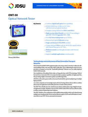
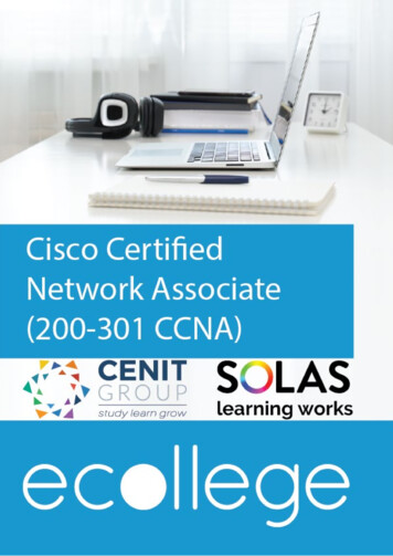
Basic Principles and Background7l1l2 From sourcesl3l1 l 2 l 3To fiberMultiplexerFigure 2.3 Principle of multiplexing by diffraction on an optical grating: Wavelengths l1,l2, l3 coming from different directions are diffracted in the same directioninto a single-transmission fiber.2.5 Wavelength AllocationThus far, the ITU-T standards recommends 81 channels in the C band witha constant spacing of 50 GHz anchored at 193.1 THz. This range can beextended to the L band (191.4 to 185.9 THz) where sources and amplifiersbecome available now. This will add 111 channels at 50-GHz spacing (seeTable 2.1).2.6 Optical Wavelength/Optical Frequency ConversionDepending on one s background (the classical optical field or the microwavefield), one generally prefers to represent light vibrations according to theirwavelengths in vacuum (the wavelength varies with the medium) or according to their frequencies (invariant of the medium). In order to evaluate thedifferent results given in scientific papers, it is useful to be able to translatequickly.It is well known that:l cnwhere c is the speed of light (c 2.9972458 106 m/s), l is the wavelength invacuum, and n is the optical frequency.
8DWDM Fundamentals, Components, and ApplicationsTable 2.1Frequency Standards with Corresponding WavelengthsC Band(196.1 192.1 THz)L Band(191.4 185.9 THz)Frequency(THz)Wavelength (Vacuum)(nm)Frequency(THz)Wavelength 3.41,550.12188.71,588.73
Basic Principles and BackgroundTable 2.1 (continued)C Band(196.1 192.1 THz)L Band(191.4 185.9 THz)Frequency(THz)Wavelength (Vacuum)(nm)Frequency(THz)Wavelength 559.79187.51,598.89192.11,560.61187.41,599.75 187.31,600.6 187.21,601.46 187.11,602.31 1871,603.17 186.91,604.03 186.81,604.88 186.71,605.74 186.61,606.6 186.51,607.47 186.41,608.33 186.31,609.19 186.21,610.06 186.11,610.92 1861,611.79 185.91,612.659
10DWDM Fundamentals, Components, and ApplicationsTherefore, l l2 ncIn practice,l 299,792.458nwith l in nm and n in GHz l nm n GHz l2mm0.310 3Thus, 100-GHz spacing at 1.55-mm wavelength is equivalent to a spacing of0.8 nm.2.7 How Many Channels?There is actually about 15,000 GHz of optical frequency bandwidth in each1,300- and 1,550-nm window. With a 10 Gbps bit rate, the uncertainty relationship gives approximately 10 GHz as the limit for optical frequency spacing. This would mean 1,500 channels! But the fiber nonlinearity has alwaysset the limit to a few hundred channels in practical applications.For the component itself at this limit, the optical crosstalk is the mainproblem. Acceptable 160-channel grating-WDM components are alreadymanufactured. We believe that many more channels are feasible. Threethousand-channel classical-grating spectrometers are commonly used, whynot WDM networks with a few hundred channels? In fact, the main problemis acquiring enough stable fixed or tunable sources. Today, the practical limitis a few tens of sources spaced at 50 GHz. The number of channels willdepend on the progress on the sources. It is worth pointing out that an optical frequency chain-generation from a single supercontinuum source withover 1,000 channels at 12.5-GHz spacing has been proposed by H. Takara,et al. in ECOC 2000 (see Chapter 4).
Basic Principles and Background112.8 Some Definitions2.8.1LossesThe multiplexer must combine the signals with minimal losses. Those lossesPj are expressed in decibels (dB) at each wavelength lj by: Φj P j 10 log Φ0 where Fj is the optical power injected into the transmission line and F0 is theincident power at lj.2.8.2CrosstalkAt the other end of the fiber, the signals at the different wavelengths areseparated by a demultiplexer which, like the multiplexer, must have minimallosses. The optical crosstalk Dij of a channel i on a channel j is: Φij Dij 10log Φjj where Fij is the residual optical power of channel i at wavelength li in channel j and Fjj the exit optical power in channel j at wavelength λj.The total optical crosstalk in channel j is: Φij i j D j 10log Φjj This defect is merely due to the demultiplexer when sources with spectralwidths much smaller than the multiplexer spectral passbands are used. But italso becomes necessary to take into account the multiplexer crosstalk in othercases. In such cases (such as LED slicing) the optical crosstalk is a complicated function of sources, multiplexer and demultiplexer.The electrical crosstalk also depends on the receivers. At equivalentreceiver sensitivity, in general, electrical crosstalk is twice as small in decibelsas the optical crosstalk. The electrical crosstalk of a system also depends onthe relative power and spectral width of the emitters, on the fiber spectral
12DWDM Fundamentals, Components, and Applicationstransmission, and on the receiver s sensitivity variation with wavelength. Forexample, the difference is about 50 dB in a silicon receiver between 0.8 mm(high sensitivity) and 1.3 or 1.5 mm (almost no sensitivity).When the same optical component performs multiplexing of somewavelengths and demultiplexing of the other wavelengths, we use a similarcrosstalk definition, but the term near-end crosstalk is used for the parasiticeffect of sources on receivers in the vicinity of these sources. The crosstalkcoming from sources located at the other end of the line is called far-endcrosstalk. It is obvious that the intrinsic near-end crosstalk of a componentmust be several orders of magnitude lower than its far-end crosstalk specification because the noise of sources not attenuated by the transmission line issuperimposed through the component crosstalk to the signal of a sourceattenuated in the transmission line. Components with intrinsic near-endoptical crosstalk lower than 120 dB have been manufactured [5]. Thenear-end crosstalk also depends on the different reflections along the line, inparticular on the number of connectors and on their location along the transmission line.2.9 Solitons2.9.1Soliton PropagationThe pulse broadening induced by chromatic dispersion can be compensatedfor by a self-phase shift induced by refraction index variations upon the fieldintensity (known as the Kerr effect) for particular pulses that have a criticalpower and shape called solitons. With silica glass the nonlinear index isn n0 3.2 10 16 I, with I in watt/cm2 and in which n0 is the index at anarbitrary low-intensity I. The response time of this phenomenon is arisingfrom electronic structure distortion in less than 1 fs (10 15s 1 fs) and fromnuclei motion in about 100 fs in silica.In soliton propagation, the velocity of the trailing half of the pulsetends to be increased and the velocity of the leading half of the pulse tends tobe decreased by the nonlinear effect; this compensates for the reverse effectdue to f
3.3.5 Typical Specifications of Available Bragg Grating DWDM 31 3.4 Optical Multidielectric Filters 32 3.4.1 General Principles 32 3.4.2 Materials and Processes for Enhanced Performances 37