Transcription
Introduction to DWDM TechnologyCorporate HeadquartersCisco Systems, Inc.170 West Tasman DriveSan Jose, CA 95134-1706USAhttp://www.cisco.comTel: 408 526-4000800 553-NETS (6387)Fax: 408 526-4100Customer Order Number:Text Part Number: OL-0884-01
THE SPECIFICATIONS AND INFORMATION REGARDING THE PRODUCTS IN THIS MANUAL ARE SUBJECT TO CHANGE WITHOUTNOTICE. ALL STATEMENTS, INFORMATION, AND RECOMMENDATIONS IN THIS MANUAL ARE BELIEVED TO BE ACCURATE BUT AREPRESENTED WITHOUT WARRANTY OF ANY KIND, EXPRESS OR IMPLIED. USERS MUST TAKE FULL RESPONSIBILITY FOR THEIRAPPLICATION OF ANY PRODUCTS.THE SOFTWARE LICENSE AND LIMITED WARRANTY FOR THE ACCOMPANYING PRODUCT ARE SET FORTH IN THE INFORMATIONPACKET THAT SHIPPED WITH THE PRODUCT AND ARE INCORPORATED HEREIN BY THIS REFERENCE. IF YOU ARE UNABLE TOLOCATE THE SOFTWARE LICENSE OR LIMITED WARRANTY, CONTACT YOUR CISCO REPRESENTATIVE FOR A COPY.The Cisco implementation of TCP header compression is an adaptation of a program developed by the University of California, Berkeley (UCB) as part ofUCB’s public domain version of the UNIX operating system. All rights reserved. Copyright 1981, Regents of the University of California.NOTWITHSTANDING ANY OTHER WARRANTY HEREIN, ALL DOCUMENT FILES AND SOFTWARE OF THESE SUPPLIERS ARE PROVIDED“AS IS” WITH ALL FAULTS. CISCO AND THE ABOVE-NAMED SUPPLIERS DISCLAIM ALL WARRANTIES, EXPRESSED OR IMPLIED,INCLUDING, WITHOUT LIMITATION, THOSE OF MERCHANTABILITY, FITNESS FOR A PARTICULAR PURPOSE ANDNONINFRINGEMENT OR ARISING FROM A COURSE OF DEALING, USAGE, OR TRADE PRACTICE.IN NO EVENT SHALL CISCO OR ITS SUPPLIERS BE LIABLE FOR ANY INDIRECT, SPECIAL, CONSEQUENTIAL, OR INCIDENTALDAMAGES, INCLUDING, WITHOUT LIMITATION, LOST PROFITS OR LOSS OR DAMAGE TO DATA ARISING OUT OF THE USE ORINABILITY TO USE THIS MANUAL, EVEN IF CISCO OR ITS SUPPLIERS HAVE BEEN ADVISED OF THE POSSIBILITY OF SUCH DAMAGES.AccessPath, AtmDirector, Browse with Me, CCDA, CCDE, CCDP, CCIE, CCNA, CCNP, CCSI, CD-PAC, CiscoLink, the Cisco NetWorks logo, the CiscoPowered Network logo, Cisco Systems Networking Academy, the Cisco Systems Networking Academy logo, Fast Step, Follow Me Browsing, FormShare,FrameShare, GigaStack, IGX, Internet Quotient, IP/VC, iQ Breakthrough, iQ Expertise, iQ FastTrack, the iQ Logo, iQ Net Readiness Scorecard, MGX,the Networkers logo, Packet, RateMUX, ScriptBuilder, ScriptShare, SlideCast, SMARTnet, TransPath, Unity, Voice LAN, Wavelength Router, andWebViewer are trademarks of Cisco Systems, Inc.; Changing the Way We Work, Live, Play, and Learn, Discover All That’s Possible, and Empoweringthe Internet Generation, are service marks of Cisco Systems, Inc.; and Aironet, ASIST, BPX, Catalyst, Cisco, the Cisco Certified Internetwork Expert logo,Cisco IOS, the Cisco IOS logo, Cisco Systems, Cisco Systems Capital, the Cisco Systems logo, Enterprise/Solver, EtherChannel, EtherSwitch, FastHub,FastSwitch, IOS, IP/TV, LightStream, MICA, Network Registrar, PIX, Post-Routing, Pre-Routing, Registrar, StrataView Plus, Stratm, SwitchProbe,TeleRouter, and VCO are registered trademarks of Cisco Systems, Inc. and/or its affiliates in the U.S. and certain other countries.All other trademarks mentioned in this document or Web site are the property of their respective owners. The use of the word partner does not imply apartnership relationship between Cisco and any other company. (0104R)Introduction to DWDM TechnologyCopyright 2000, Cisco Systems, Inc.All rights reserved.
C O N T E N T SPrefaceviiAdditional ReadingCHAPTER1Introducing DWDMvii1-1Global Network HierarchyEconomic Forces1-11-3Bandwidth Demand1-3Competition and Reliability1-4Options for Increasing Carrier BandwidthIncrease the Bit Rate1-51-5Increase the Number of WavelengthsTime-Division MultiplexingSONET and TDM1-61-61-6Wavelength Division MultiplexingTDM and WDM Compared1-91-9Additional Drivers in Metropolitan Area NetworksValue of DWDM in the Metropolitan AreaRequirements in the Metropolitan AreaWhy DWDM?1-121-13Enhancing Performance and ReliabilityNetwork Management CapabilityAdditional Benefits21-111-12SONET with DWDMCHAPTER1-101-151-161-16Fundamentals of DWDM Technology2-1Evolution of Fiber Optic Transmission2-1Development of DWDM TechnologyDWDM System Functions2-22-4Enabling Technologies2-5Components and Operation2-5Introduction to DWDM TechnologyOL-0884-01iii
ContentsOptical Fibers2-6How Fiber Works2-6Multimode and Single-Mode FiberSingle-Mode Fiber Designs2-8Transmission 02-12Light Sources and Detectors2-13Light Emitters—LEDs and LasersITU Grid2-132-14Light Detectors2-15Optical Amplifiers2-16Erbium-Doped Fiber AmplifierMultiplexers and Demultiplexers2-162-17Techniques for Multiplexing and DemultiplexingOptical Add/Drop MultiplexersInterfaces to DWDM2-202-20Operation of a Transponder Based DWDM SystemCHAPTER3DWDM in Metropolitan Area NetworksATM3-23-23-2Fibre Channel3-3Dynamic Packet TransportFDDI3-13-1Gigabit EthernetIP2-213-1Technologies in the Metropolitan MarketSONET/SDH2-183-33-4Support for Legacy Traffic3-4Applications and Services in the MANStorage Area Networks3-53-5Migration from SONET/SDH3-7Introduction to DWDM TechnologyivOL-0884-01
ContentsTopologies and Protection Schemes for DWDMPoint-to-Point TopologiesRing Topologies3-93-10Mesh Topologies3-11Practical Considerations in Deploying DWDMOptical Power Budget3-13Interoperability Issues3-14Future of DWDM3-93-133-14INDEXIntroduction to DWDM TechnologyOL-0884-01v
ContentsIntroduction to DWDM TechnologyviOL-0884-01
PrefaceThis Introduction to DWDM Technology is intended for readers who want to gain a basic understandingof dense wavelength division multiplexing (DWDM) technology and its role in metropolitan areanetworks (MANs). The contents are organized as follows:ChapterTitleDescriptionChapter 1Introducing DWDMDifferentiates the MAN from other segmentsof the global network; describes the drivingforces behind DWDM; contrasts time divisionmultiplexing (TDM) with wavelengthdivision multiplexing (WDM); presents theadvantages of DWDM in the MANChapter 2Fundamentals of DWDM Summarizes the evolution of fiber opticTechnologytransmission and DWDM technology; brieflydescribes the main components; explains theoperation of a DWDM systemChapter 3DWDM in MetropolitanArea NetworksSurveys the data link and networktechnologies used in the MAN; describessample applications for DWDM; presentssample topologies and protection schemes;offers practical considerations for deployingDWDMAdditional ReadingReaders who are interested in more detailed information about optical networking will find that there isa wide selection of resources available, especially on SONET. The following publications are good,basic texts: Dutton, Harry J. R. Understanding Optical Communications. Research Triangle Park: IBMCorporation; 1998. Goff, David R. Fiber Optic Reference Guide, 2nd edition. Boston: Focal Press; 1999. Goralski, Walter J. SONET, 2nd edition. New York: McGraw-Hill; 2000. Kaminow, Ivan P., and Koch, Thomas L., eds. Optical Fiber Telecommunications. San Diego:Academic Press; 1997.Introduction to DWDM TechnologyOL-0884-01vii
PrefaceAdditional ReadingThe following publication is a detailed text on DWDM, particularly from the standpoint of theory andoptical components:Kartalopoulos, Stamatios V. Introduction to DWDM Technology: Data in a Rainbow. New York:IEEE Press; 1999.Although comprehensive texts specifically about DWDM are not yet plentiful, there is a variety ofinformation in the form of tutorials, white papers, and so on, to be found on the World Wide Web.For definitions of terms and acronyms used in this Introduction, refer to the Glossary of OpticalNetworking Terms.Introduction to DWDM TechnologyviiiOL-0884-01
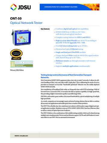
C H A P T E R1Introducing DWDMThe following discussion provides some background on why dense wavelength division multiplexing(DWDM) is an important innovation in optical networks and what benefits it can provide. We begin witha high-level view of the segments of the global network and the economic forces driving the revolutionin fiber optic networks. We then examine the differences between traditional time-division multiplexing(TDM) and wavelength division multiplexing (WDM). Finally, we explore the advantages of this newtechnology.This chapter contains the following major sections: Global Network Hierarchy, page 1-1 Economic Forces, page 1-3 Options for Increasing Carrier Bandwidth, page 1-5 Additional Drivers in Metropolitan Area Networks, page 1-10 Why DWDM?, page 1-12Global Network HierarchyIt is the nature of modern communications networks to be in a state of ongoing evolution. Factors suchas new applications, changing patterns of usage, and redistribution of content make the definition ofnetworks a work in progress. Nevertheless, we can broadly define the larger entities that make up theglobal network based on variables such as transport technology, distance, applications, and so on.One way of describing the metropolitan area network (MAN) would be to say that it is neither thelong-haul nor the access parts of the network, but the area that lies between those two (see Figure 1-1).Introduction to DWDM TechnologyOL-0884-011-1
Chapter 1Introducing DWDMGlobal Network HierarchyFigure 1-1Global Network sidential networks:- DSL- Cable modemInter-metroconnectionsSONET:- POTS- ISP POP:-IP servicesEnterprise:- Frame Relay- ESCON- Fibre Channel- Gigabit ong-Haul NetworksLong-haul networks are at the core of the global network. Dominated by a small group of largetransnational and global carriers, long-haul networks connect the MANs. Their application is transport,so their primary concern is capacity. In many cases these networks, which have traditionally been basedon Synchronous Optical Network (SONET) or Synchronous Digital Hierarchy (SDH) technology, areexperiencing fiber exhaust as a result of high bandwidth demand.Access NetworksAt the other end of the spectrum are the access networks. These networks are the closest to the end users,at the edge of the MAN. They are characterized by diverse protocols and infrastructures, and they spana broad spectrum of rates. Customers range from residential Internet users to large corporations andinstitutions. The predominance of IP traffic, with its inherently bursty, asymmetric, and unpredictablenature, presents many challenges, especially with new real-time applications. At the same time, thesenetworks are required to continue to support legacy traffic and protocols, such as IBM’s EnterpriseSystem Connection (ESCON).Metropolitan Area NetworksBetween these two large and different networking domains lie the MANs. These networks channeltraffic within the metropolitan domain (among businesses, offices, and metropolitan areas) and betweenlarge long-haul points of presence (POPs). The MANs have many of the same characteristics as theaccess networks, such as diverse networking protocols and channel speeds. Like access networks, MANshave been traditionally SONET/SDH based, using point-to-point or ring topologies with add/dropmultiplexers (ADMs).The MAN lies at a critical juncture. On the one hand, it must meet the needs created by the dynamics ofthe ever-increasing bandwidth available in long-haul transport networks. On the other hand, it mustaddress the growing connectivity requirements and access technologies that are resulting in demand forhigh-speed, customized data services.Introduction to DWDM Technology1-2OL-0884-01
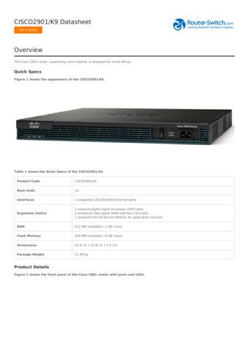
Chapter 1Introducing DWDMEconomic ForcesMetropolitan and Long-Haul Networks ComparedThere is a natural tendency to regard the MAN as simply a scaled-down version of the long-haulnetwork. It is true that networks serving the metropolitan area encompass shorter distances than in thelong-haul transport networks. Upon closer examination, however, these differences are superficialcompared to other factors. Network shape is more stable in long-haul, while topologies changefrequently in the MAN. Many more types of services and traffic types must be supported in MANs, fromtraditional voice and leased line services to new applications, including data storage, distributedapplications, and video. The long-haul, by contrast, is about big pipes.Another important way in which metropolitan networks today differ from trunk-oriented long haulnetworks is that they encompass a collection of low bit-rate asynchronous and synchronous transmissionequipment, short loops, small cross-sections, and a variety of users with varying bandwidth demands.These fundamental differences between the two types of networks have powerful implications for therequirements in the metropolitan domain. Protocol and speed transparency, scalability, and dynamicprovisioning are at least as important as capacity, which rules in the long-haul market.An Alternative ViewThe preceding breakdown of the global network represents a somewhat simplified view. In reality, thelines between the domains are not always so clear-cut. Long-haul and metropolitan networks aresometimes not clearly delineated; the same holds true for the access and metropolitan domains.Furthermore, other views of the global network exist. One, for example, defines the access network aspart of, rather than separate from, the MAN, while also including enterprise connectivity in themetropolitan domain. In this view, the metropolitan market breaks down as follows: Core—These are essentially scaled-down long-haul systems. They are considered the core of theMAN, because they interconnect carrier POPs and do not directly interface with end users. Metropolitan access—This is the segment between carrier POPs and access facilities, which couldbe equipment at customer premises or at an aggregation point. Enterprise—This is the part of the network dedicated to serving the needs of enterprises. Usingowned or leased fiber (or leased fiber capacity), connectivity is provided between geographicallydisparate enterprise sites and for new applications, such as storage area networks (SANs).Economic ForcesAs we enter the twenty-first century, it goes without saying that information services have permeatedsociety and commerce. Information, while still a tool, has become a commodity in itself. Yet theuniversal acceptance and ubiquitous adoption of information technology systems has strained thebackbones on which they were built. High demand—coupled with high usage rates, a deregulatedtelecommunications environment, and high availability requirements—is rapidly depleting thecapacities of fibers that, when installed 10 years ago, were expected to suffice for the foreseeable future.Bandwidth DemandThe explosion in demand for network bandwidth is largely due to the growth in data traffic, specificallyInternet Protocol (IP). Leading service providers report bandwidths doubling on their backbones aboutevery six to nine months. This is largely in response to the 300 percent growth per year in Internet traffic,while traditional voice traffic grows at a compound annual rate of only about 13 percent (see Figure 1-2).Introduction to DWDM TechnologyOL-0884-011-3
Chapter 1Introducing DWDMEconomic ForcesFigure 1-2Data Traffic Overtakes Voice TrafficDataTraffic 20002001Data-centric480661996At the same time that network traffic volume is increasing, the nature of the traffic itself is becomingmore complex. Traffic carried on a backbone can originate as circuit based (TDM voice and fax), packetbased (IP), or cell based (ATM and Frame Relay). In addition, there is an increasing proportion of delaysensitive data, such as voice over IP and streaming video.In response to this explosive growth in bandwidth demand, along with the emergence of IP as thecommon foundation for all services, long-haul service providers are moving away from TDM basedsystems, which were optimized for voice but now prove to be costly and inefficient. Meanwhile,metropolitan networks are also experiencing the impact of growing congestion, as well as rapidlychanging requirements that call for simpler and faster provisioning than is possible with older equipmentand technologies. Of key importance in the metropolitan area is the growth in storage area networks(SANs), discussed in the “Storage Area Networks” section on page 3-5.Competition and ReliabilityWhile the demand for bandwidth is driven largely by new data applications, Internet usage, and thegrowth in wireless communications, two additional factors come into play: competition and networkavailability.The telecommunication sector, long a beneficiary of government regulation, is now a highly competitiveindustry. Competition was first introduced into the U.S. long-distance market in 1984, and the 1996Telecommunications Reform Act is now resulting in an increasingly broad array of new operators. Thesenew carriers are striving to meet the new demand for additional services and capacity.There are two main effects on the industry from competition: Enhanced services are created by newcomers trying to compete with incumbents. In themetropolitan market, for example, there are broadband wireless and DSL services to homes andsmall and medium-sized business, high-speed private line and VPN services to corporations, andtransparent LAN services to enterprise network customers. New carriers coming onto the scene create new infrastructure so that they do not have to lease fromexisting operators. Using this strategy, they have more control over provisioning and reliability.Introduction to DWDM Technology1-4OL-0884-01
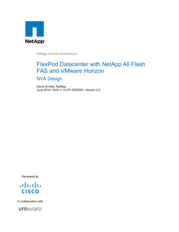
Chapter 1Introducing DWDMOptions for Increasing Carrier BandwidthAs telecommunications and data services have become more critical to business operations, serviceproviders have been required to ensure that their networks are fault tolerant. To meet these requirements,providers have had to build backup routes, often using simple 1:1 redundancy in ring or point-to-pointconfigurations. Achieving the required level of reliability, however, means reserving dedicated capacityfor failover. This can double the need for bandwidth on an already strained infrastructure (seeFigure 1-3).Figure 1-3Reserving Bandwidth Reduces Overall CapacityBandwidth n/2Dedicated protection48067Bandwidth nNo protectionOptions for Increasing Carrier BandwidthFaced with the challenge of dramatically increasing capacity while constraining costs, carriers have twooptions: Install new fiber or increase the effective bandwidth of existing fiber.Laying new fiber is the traditional means used by carriers to expand their networks. Deploying newfiber, however, is a costly proposition. It is estimated at about 70,000 per mile, most of which is thecost of permits and construction rather than the fiber itself. Laying new fiber may make sense only whenit is desirable to expand the embedded base.Increasing the effective capacity of existing fiber can be accomplished in two ways: Increase the bit rate of existing systems. Increase the number of wavelengths on a fiber.Increase the Bit RateUsing TDM, data is now routinely transmitted at 2.5 Gbps (OC-48) and, increasingly, at 10 Gbps(OC-192); recent advances have resulted in speeds of 40 Gbps (OC-768). The electronic circuitry thatmakes this possible, however, is complex and costly, both to purchase and to maintain. In addition, thereare significant technical issues that may restrict the applicability of this approach. Transmission atOC-192 over single-mode (SM) fiber, for example, is 16 times more affected by chromatic dispersionthan the next lower aggregate speed, OC-48. The greater transmission power required by the higher bitrates also introduces nonlinear effects that can affect waveform quality. Finally, polarization modedispersion, another effect that limits the distance a light pulse can travel without degradation, is also anissue. These characteristics of light in fiber are discussed further in the “Optical Fibers” section onpage 2-6.Introduction to DWDM TechnologyOL-0884-011-5
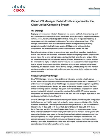
Chapter 1Introducing DWDMOptions for Increasing Carrier BandwidthIncrease the Number of WavelengthsIn this approach, many wavelengths are combined onto a single fiber. Using wavelength divisionmultiplexing (WDM) technology several wavelengths, or light colors, can simultaneously multiplexsignals of 2.5 to 40 Gbps each over a strand of fiber. Without having to lay new fiber, the effectivecapacity of existing fiber plant can routinely be increased by a factor of 16 or 32. Systems with 128 and160 wavelengths are in operation today, with higher density on the horizon. The specific limits of thistechnology are not yet known.Time-Division MultiplexingTime-division multiplexing (TDM) was invented as a way of maximizing the amount of voice trafficthat could be carried over a medium. In the telephone network before multiplexing was invented, eachtelephone call required its own physical link. This proved to be an expensive and unscalable solution.Using multiplexing, more than one telephone call could be put on a single link.TDM can be explained by an analogy to highway traffic. To transport all the traffic from four tributariesto another city, you can send all the traffic on one lane, providing the feeding tributaries are fairlyserviced and the traffic is synchronized. So, if each of the four feeds puts a car onto the trunk highwayevery four seconds, then the trunk highway would get a car at the rate of one each second. As long asthe speed of all the cars is synchronized, there would be no collision. At the destination the cars can betaken off the highway and fed to the local tributaries by the same synchronous mechanism, in reverse.This is the principle used in synchronous TDM when sending bits over a link. TDM increases thecapacity of the transmission link by slicing time into smaller intervals so that the bits from multiple inputsources can be carried on the link, effectively increasing the number of bits transmitted per second (seeFigure 1-4).Figure 1-4TDM ConceptBits of informationTDM.48069Transmission linkWith TDM, input sources are serviced in round-robin fashion. Though fair, this method results ininefficiency, because each time slot is reserved even when there is no data to send. This problem ismitigated by the statistical multiplexing used in Asynchronous Transfer Mode (ATM). Although ATMoffers better bandwidth utilization, there are practical limits to the speed that can be achieved due to theelectronics required for segmentation and reassembly (SAR) of ATM cells that carry packet data.SONET and TDMThe telecommunications industry adopted the Synchronous Optical Network (SONET) or SynchronousDigital Hierarchy (SDH) standard for optical transport of TDM data. SONET, used in North America,and SDH, used elsewhere, are two closely related standards that specify interface parameters, rates,framing formats, multiplexing methods, and management for synchronous TDM over fiber.Introduction to DWDM Technology1-6OL-0884-01
Chapter 1Introducing DWDMOptions for Increasing Carrier BandwidthSONET/SDH takes n bit streams, multiplexes them, and optically modulates the signal, sending it outusing a light emitting device over fiber with a bit rate equal to (incoming bit rate) x n. Thus trafficarriving at the SONET multiplexer from four places at 2.5 Gbps will go out as a single stream at 4 x2.5 Gbps, or 10 Gbps. This principle is illustrated in Figure 1-5, which shows an increase in the bit rateby a factor of four in time slot T.Figure 1-5SONET TDMBit rate 2.5 GbpsLink rate (2.5 Gbps x 4 10 Gbps)10 GbpsIncoming stream(T)48070(T)The original unit used in multiplexing telephone calls is 64 kbps, which represents one phone call.Twenty-four (in North America) or thirty-two (outside North America) of these units are multiplexedusing TDM into a higher bit-rate signal with an aggregate speed of 1.544 Mbps or 2.048 Mbps fortransmission over T1 or E1 lines, respectively.The hierarchy for multiplexing telephone calls is shownin Table 1-1.Table 1-1Telco Multiplexing HierarchySignalBit RateVoice SlotsDS064 kbps1 DS0DS11.544 Mbps24 DS0sDS26.312 Mbps96 DS0sDS344.736 Mbps28 DS1sThese are the basic building blocks used by SONET/SDH to multiplex into a standard hierarchy ofspeeds, from STS-1 at 51.85 Mbps to STS-192/STM-64 at 10 Gbps. Table 1-2 shows the relationshipbetween the telco signal rates and the most commonly used levels of the SONET/SDH hierarchy(OC-768 is not yet common).Table 1-2SONET/SDH Multiplexing HierarchyOptical CarrierSONET/SDH SignalBit RateCapacityOC-1STS-151.84 Mbps28 DS1s or 1 DS3OC-3STS-3/STM-1155.52 Mbps84 DS1s or 3 DS3sOC-12STS-12/STM-4622.08 Mbps336 DS1s or 12 DS3sOC-48STS-48/STM-162488.32 Mbps1344 DS1s or 48 DS3sOC-192STS-192/STM-649953.28 Mbps5379 DS1s or 192 DS3sIntroduction to DWDM TechnologyOL-0884-011-7
Chapter 1Introducing DWDMOptions for Increasing Carrier BandwidthFigure 1-6 depicts this multiplexing and aggregation hierarchy. Using a standard called virtualtributaries for mapping lower-speed channels into the STS-1 payload, the 28 DS1 signals can be mappedinto the STS-1 payload, or they can be multiplexed to DS3 with an M13 multiplexer and fit directly intothe STS-1. Note also that ATM and Layer 3 traffic, using packet over SONET (POS), can feed into theSONET terminal from switches equipped with SONET interfaces.Figure 1-6TDM and SONET S1STS-1M1324 or30DS3SONET terminal28STS-3CUnchannelizedSTSxmultiplexing To opticalcomponentsATM switchATM cellsRouter/Layer 3switch48071IP datagrams (Packet over SONET)SONET/SDH does have some drawbacks. As with any TDM, the notions of priority or congestion donot exist in SONET or SDH. Also, the multiplexing hierarchy is a rigid one. When more capacity isneeded, a leap to the next multiple must be made, likely resulting in an outlay for more capacity than isinitially needed. For example, the next incremental step from 10 Gbps (STS-192) TDM is 40 Gbps(STS-768). Also, since the hierarchy is optimized for voice traffic, there are inherent inefficiencies whencarrying data traffic with SONET frames. Some of these inefficiencies are shown in Table 1-3. DWDM,by contrast, can transport any protocol, including SONET, without special encapsulation.Table 1-3Ethernet in SONET InefficienciesEthernetSONET/SDH SignalBit RateWasted Bandwidth10BASE-T (10 Mbps)STS-151.8540 Mbps80.709%100BASE-T (100 Mbps)STS-3/STM-1155.520 Mbps35.699%2488.32 Mbps59.812%1000BASE-T (1000 Mbps) STS-48/STM-16To summarize, the demand placed on the transport infrastructure by bandwidth-hungry applications andthe explosive growth of the Internet has exceeded the limits of traditional TDM. Fiber, which oncepromised seemingly unlimited bandwidth, is being exhausted, and the expense, complexity, andscalability limitations of the SONET infrastructure are becoming increasingly problematic.Introduction to DWDM Technology1-8OL-0884-01
Chapter 1Introducing DWDMOptions for Increasing Carrier BandwidthWavelength Division MultiplexingWDM increases the carrying capacity of the physical medium (fiber) using a completely differentmethod from TDM. WDM assigns incoming optical signals to specific frequencies of light(wavelengths, or lambdas) within a certain frequency band. This multiplexing closely resembles the wayradio stations broadcast on different wavelengths without interfering with each other (see Figure 1-7).Because each channel is transmitted at a different frequency, we can select from them using a tuner.Another way to think about WDM is that each channel is a different color of light; several channels thenmake up a “rainbow.”Figure 1-7Increasing Capacity with WDMWDM48072Independent bit ratesand formatsNoteThe term wavelength is used instead of the term frequency to avoid confusion with otheruses of frequency. Wavelength is often used interchangeably with lambda and channel.In a WDM system, each of the wavelengths is launched into the fiber, and the signals are demultiplexedat the receiving end. Like TDM, the resulting capacity is an aggregate of the input signals, but WDMcarries each input signal independently of the others. This means that each channel has its own dedicatedbandwidth; all signals arrive at the same time, rather than being broken up and carried in time slots.The difference between WDM and dense wavelength division multiplexing (DWDM) is fundamentallyone of only degree. DWDM spaces the wavelengths more closely than does WDM, and therefore has agreater overall capacity.The limits of this spacing are not precisely known, and have probably not beenreached, though systems are available in mid-year 2000 with a capacity of 128 lambdas on one fiber.DWDM has a number of other notable features, which are discussed in greater detail in the followingchapters. These include the ability to amplify all the wavelengths at once without first converting themto electrical signals, and the ability to carry signals of different speeds and types simultaneously andtransparently over the fiber (protocol and bit rate independence).NoteWDM and DWDM use single-mode fiber to carry multiple lightwaves of differingfrequencies. This should not be confused with transmission over multimode fiber, in whichlight is launched into the fiber at different angles, resulting in different “modes” of light.A single wavelength is used in multimode transmission.TDM and WDM ComparedSONET TDM takes synchronous and asynchronous signals and multiplexes them to a single higher bitrate for transmission at a single wavelength over fiber. Source signals may have to be converted fromelectrical to optical, or from optical to electrical and back to optical before being multiplexed. WDMIntroduction to DWDM TechnologyOL-0884-011-9
Chapter 1Introducing DWDMAdditional Drivers in Metropolitan Area Networkstakes multiple optical
CONTENTS iii Introduction to DWDM Technology OL-0884-01 Preface vii Additional Reading vii CHAPTER 1 Introducing DWDM 1-1 Global Network Hierarchy 1-1 Economic Forces 1-3 Bandwidth Demand 1-3 Competition and Reliability 1-4 Options for Increasing Carrier Bandwidth 1-5 Increase the Bit Rate 1-5 Increase the Number of Wavelengths 1-6 Time-Division Multiplexing 1-6 SONET and TDM 1-6