Transcription
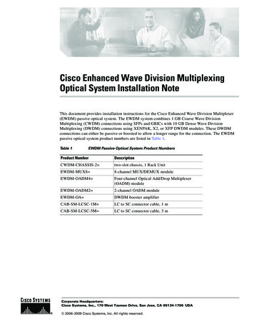
Cisco Enhanced Wave Division MultiplexingOptical System Installation NoteThis document provides installation instructions for the Cisco Enhanced Wave Division Multiplexer(EWDM) passive optical system. The EWDM system combines 1 GB Coarse Wave DivisionMultiplexing (CWDM) connections using SFPs and GBICs with 10 GB Dense Wave DivisionMultiplexing (DWDM) connections using XENPAK, X2, or XFP DWDM modules. These DWDMconnections can either be passive or boosted to allow a longer range for the connection. The EWDMpassive optical system product numbers are listed in Table 1.Table 1EWDM Passive Optical System Product NumbersProduct NumberDescriptionCWDM-CHASSIS-2 two-slot chassis, 1 Rack UnitEWDM-MUX8 8-channel MUX/DEMUX moduleEWDM-OADM4 Four-channel Optical Add/Drop Multiplexer(OADM) moduleEWDM-OADM2 2-channel OADM moduleEWDM-OA DWDM booster amplifierCAB-SM-LCSC-1M LC to SC connector cable, 1 mCAB-SM-LCSC-5M LC to SC connector cable, 5 mCorporate Headquarters:Cisco Systems, Inc., 170 West Tasman Drive, San Jose, CA 95134-1706 USA 2006–2009 Cisco Systems, Inc. All rights reserved.
ContentsContentsThis installation note contains the following sections: Overview, page 2 Safety Overview, page 15 Installing the EWDM Passive Optical System, page 21 Connecting the EWDM Passive Optical System to Your System, page 24 Specifications, page 29 Translated Safety Warnings, page 33 Obtaining Documentation and Submitting a Service Request, page 41OverviewThe Cisco EWDM passive optical system provides optical networking support for high-speed datacommunication at 10 GBps for metropolitan area networks (MANs) using CWDM and DWDM opticalwavelengths in both ring or point-to-point configurations.The Cisco EWDM passive optical system includes these components: Two-slot chassis OADMs– Eight-channel– Four-channel– Two-channel An optical amplifierCWDM Two-slot ChassisThe CWDM Two-slot chassis (CWDM-CHASSIS-2) is a standard 19-inch chassis that is one rack unit(RU) in height. Each CWDM two-slot chassis can hold two OADM modules or one OADM and anoptical amplifier. You can install the CWDM two-slot chassis in the same equipment rack as your otherswitching equipment or in an adjacent rack.Cisco Enhanced Wave Division Multiplexing Optical System Installation Note278-17894-02
OverviewEWDM OADMsThe EWDM OADMs are passive devices that can multiplex/demultiplex or add/drop wavelengths frommultiple fibers onto one optical fiber. The OADM connectors are labeled with the DWDM wavelengthsto be multiplexed/demultiplexed. All OADMs are the same size. Two OADM modules can be installedin a CWDM two-slot chassis (CWDM-CHASSIS-2). There are three different types of EWDM OADMmodules8-Channel Multiplexer/Demultiplexer (EWDM-MUX8 )The 8-Channel Multiplexer/Demultiplexer (EWDM-MUX8 ) allows you to multiplex/demultiplex eightDWDM channels and combine them with up to 8 CWDM channels into one pair of fiber. Dual fiber isused for both the network connection and the transceiver connections. The eight available wavelengthsare 1542.94 nm, 1542.14 nm, 1540.56 nm, 1539.77 nm, 1538.98 - 1560.61 nm, 1559.79 nm, and 1558.98nm. The multiplexer/demultiplexer, shown in Figure 1, is equipped with a port that allows you to connectto the booster amplifier.Eight Channel Multiplexer/Demultiplexer (EWDM-MUX8 ) Front PanelTXEWDMMUX8NETWORKAMPRXINTXCWDM-UPG RXTX1560.61RX TX1558.98RXTX1542.14RX TX1539.77RXOUTTX1559.79RX TX1542.94RXTX1540.56RX TX1538.98RXINVISIBLE LASERDO NOT VIEWTable 2181009Figure 1EWDM-MUX8 Channel PlanEWDM Channel IDWavelength 9871559.7981560.61Four-Channel and Two- Channel OADM (EWDM-OADM4 and EWDM-OADM2 )The four-channel and two-channel OADM (EWDM-OADM4 and EWDM-OADM2 ) allows you torespectively add/drop four or two channels (with different wavelengths) and combine them with up to 8CWDM channels into one pair of fiber. Dual fiber is used for both the network connection and thetransceiver connections. The two OADMs, shown in Figure 2 and Figure 3, are equipped with a port thatallows you to connect to the booster amplifier and support the following wavelengths: EWDM-OADM4—1542.94 nm, 1542.14 nm, 1540.56 nm, 1539.77 nm. EWDM-OADM2—1560.61 nm, 1559.79 nm.Cisco Enhanced Wave Division Multiplexing Optical System Installation Note78-17894-023
DWDM Booster Amplifier (EWDM-OA )Four-channel OADM (EWDM-OADM4 ) Front PanelTXEWDMOADM4NETWORKAMPRXINTXTX1542.94RX TX1540.56RXOUTCWDM-UPG RXTX1542.14RX TX1539.77RXINVISIBLE LASERDO NOT VIEWTable 3EWDM-OADM4 Channel PlanEWDM Channel IDWavelength (nm)21539.7731540.5641542.1451542.94Two-Channel OADM (EWDM-OADM2) Front -UPG RXTX1559.79RXINVISIBLE LASERDO NOT VIEW181011Figure 3Table 4181010Figure 2EWDM-OADM2 Channel PlanEWDM Channel IDWavelength (nm)71559.7981560.61DWDM Booster Amplifier (EWDM-OA )The DWDM Booster Amplifier (EWDM-OA ) integrates a 10-GB connection over 1-GB CWDMnetworks without sacrificing the reach of these networks, and compensates for the power budget gapbetween the 10-GB DWDM pluggable transceivers and the low speed 1-GB GBIC/SFP. Dual fiber isused for both the network and the transciever connections.The booster amplifier boosts the signal power and therefore the maximum distance for the 10 GBEthernet connection.The booster amplifier modules are equipped with a monitor port that allows you to monitor amplifierconditions and adjust settings.Cisco Enhanced Wave Division Multiplexing Optical System Installation Note478-17894-02
DWDM Booster Amplifier (EWDM-OA )Figure 4Booster Amplifier (EWDM-OA ) Front Panel1234POWERINALARM56789100-240 VAC IN 50-60Hz 0.25AINOUTINVISIBLE LASERDO NOT VIEW181019RS-2321AC inlet6RS-232 Management connection2Power LED7LC connector3In LED8Ground4ALARM LED9Captive screw5Reset buttonTable 5 explains the meanings for the LEDs on the booster amplifier.Table 5Booster Amplifier LED MeaningsLEDColorMeaningPOWERGreenPower is goodRedPower failure or under-voltageGreenInput in rangeRedInput out of rangeGreenNormalOrangeMinor problemRedSevere problemINALARMThe reset button is used to restart the unit without unplugging it.The rollover cable needed to connect to the console port is not included. To connect a terminal to theamplifier, use a PC, a rollover cable, and a terminal emulation program with the following settings: 9600 kbps 1 stop bit 8 data bits No parityCisco Enhanced Wave Division Multiplexing Optical System Installation Note78-17894-025
DWDM Booster Amplifier (EWDM-OA )Table 6 shows the commands available when you connect to the booster amplifier console port.Table 6Amplifier Management CommandsCommandDescriptionReturn syntaxEcho [on off]Set command line echoing to on or off.If no argument is provided the currentsetting is displayed. ECHOECHO: ON ECHO OFFECHO: OFFshow [pin pout psig gain]Displays input power, total outputpower and signal gain. The Signalpower is total power minus theestimated ASE power. SHOW PINPIN -10.00 dBm SHOW POUTPOUT -10.00 dBm SHOW PSIGPSIG -10.00 dBm SHOW GAINGAIN 10.00 dBshow pump statusDisplays the status of the pump laser. SHOW PUMP STATUSPUMP ILD 123.5 mAPUMP TEMP 50.1 CPUMP ITC 259.5 mAPUMP VTC 2.745 VILD: laser diode currentTEMP: laser diode temperatureITC: TEC currentVTC: TEC voltageshow alarm [los lop eip ]Displays loss of signal, loss of power,and excess input power settings for thealarms. SHOW ALARM LOSALARM LOS: OFF SHOW ALARM LOPALARM LOP: OFF SHOW ALARM EIPALARM EIP: OFF SHOW ALARMALARM LOS: OFFALARM LOP: OFFALARM EIP: OFFShow InventoryProvides product identification data.PID is the product identification.VID is the version identification.S/N is the Serial Number.CLEI is the CLEI code. SHOW INVENTORYINVENTORY PID: ABCD11111111INVENTORY VID: ABCINVENTORY S/N: ABCD1111111INVENTORY CLEI: ABCD111111CWDM GBIC and CWDM SFP TransceiversThe CWDM GBIC and CWDM SFP transceivers are hot-swappable input/output devices that link yourswitching module to the CWDM passive optical system using a pair of single-mode fiber-optic cables.The two transceiver types have different form factors and use different fiber-optic cable connectors.Figure 5 shows a CWDM GBIC transceiver which uses an SC connector, and Figure 6 shows a CWDMSFP transceiver which uses an LC connector.Cisco Enhanced Wave Division Multiplexing Optical System Installation Note678-17894-02
DWDM Booster Amplifier (EWDM-OA )CWDM GBIC71100 SINGCWD 0BASE LE-MM-G -CW ODBIC-15 DM GB E50 ICFigure 5264Warning84472531Color label identifying laser wavelength5Optical bore dust plug2Alignment groove6Receive optical bore3Spring clip7Color dot identifying laser wavelength4Transmit optical boreUse of controls, adjustments, or performing procedures other than those specified may result inhazardous radiation exposure. Statement 1057Figure 6CWDM SFPCWC DlL as MNS # s -S/N 50 1 F: 7 21 PO / C 14H 01 F 71 R 02 1 3 0 23 4 G4 05 .6 0 13 0-13Color arrow on labelReceive optical boreTransmit optical boreBail clasp113753DustplugThe CWDM GBIC and CWDM SFP transceivers are available in eight wavelengths. (See Table 7.) EachCWDM GBIC and CWDM SFP transceiver is color coded to match the connector colors on the OADMmodules.Table 7CWDM GBIC and SFP Transceiver Color CodesGBIC TransceiverProduct NumberSFP TransceiverProduct NumberDescriptionConnectorColor CodeCWDM-GBIC-1470 CWDM-SFP-1470 1000BASE-CWDM, 1470 nmGrayCWDM-GBIC-1490 CWDM-SFP-1490 1000BASE-CWDM, 1490 nmVioletCWDM-GBIC-1510 CWDM-SFP-1510 1000BASE-CWDM, 1510 nmBlueCisco Enhanced Wave Division Multiplexing Optical System Installation Note78-17894-027
DWDM Booster Amplifier (EWDM-OA )Table 7CWDM GBIC and SFP Transceiver Color Codes (Continued)GBIC TransceiverProduct NumberSFP TransceiverProduct NumberDescriptionConnectorColor CodeCWDM-GBIC-1530 CWDM-SFP-1530 1000BASE-CWDM, 1530 nmGreenCWDM-GBIC-1550 CWDM-SFP-1550 1000BASE-CWDM, 1550 nmYellowCWDM-GBIC-1570 CWDM-SFP-1570 1000BASE-CWDM, 1570 nmOrangeCWDM-GBIC-1590 CWDM-SFP-1590 1000BASE-CWDM, 1590 nmRedCWDM-GBIC-1610 CWDM-SFP-1610 1000BASE-CWDM, 1610 nmBrownFor information on installing, removing, and maintaining the CWDM GBIC and SFP transceivers, referto the Cisco CWDM GBIC and CWDM SFP Installation Note that accompanies the CWDM GBIC andCWDM SFP transceivers.DWDM XENPAK, X2, and XFP TransceiversThe DWDM XENPAK, X2, and XFP transceivers are hot-swappable input-output devices that plug into10-Gigabit Ethernet ports.Figure 7DWDM XENPAK Transceiver Features34TX299376RX11Captive installation screw3Transmit optical bore2Optical bore dust plug4Receive optical boreCisco Enhanced Wave Division Multiplexing Optical System Installation Note878-17894-02
DWDM Booster Amplifier (EWDM-OA )Figure 8DWDM X2 Transceiver Features6Latching sleeve retracted;latch extended543172Latching sleeve extended;latch retracted120754891Transmit optical bore6Module connector2Receive optical bore7Latch (extended)3Latching sleeve (retracted)8Latching sleeve (extended)4EMI gasket9Latch (retracted)5Transceiver heat sinkCisco Enhanced Wave Division Multiplexing Optical System Installation Note78-17894-029
DWDM Booster Amplifier (EWDM-OA )Figure 9DWDM XFP Transceiver Features3451214437561Transmit optical bore4bail clasp (locked position)2Receive optical bore5Dust plug3Transceiver socket connector6bail clasp (unlocked position)Table 8, Table 9, and Table 10 list the respective product numbers for DWDM XENPAK, X2, and XFPtransceivers depending on the desired band or channel.Table 8DWDM XENPAK Transceiver Module Product NumbersProduct NumberDescriptionITUChannelDWDM-XENPAK-60.61 10GBASE-DWDM 1560.61 nm XENPAK (100-GHz ITU grid) 21DWDM-XENPAK-59.79 10GBASE-DWDM 1559.79 nm XENPAK (100-GHz ITU grid) 22DWDM-XENPAK-58.98 10GBASE-DWDM 1558.98 nm XENPAK (100-GHz ITU grid) 23DWDM-XENPAK-58.17 10GBASE-DWDM 1558.17 nm XENPAK (100-GHz ITU grid) 24DWDM-XENPAK-56.55 10GBASE-DWDM 1556.55 nm XENPAK (100-GHz ITU grid) 26DWDM-XENPAK-55.75 10GBASE-DWDM 1555.75 nm XENPAK (100-GHz ITU grid) 27DWDM-XENPAK-54.94 10GBASE-DWDM 1554.94 nm XENPAK (100-GHz ITU grid) 28Cisco Enhanced Wave Division Multiplexing Optical System Installation Note1078-17894-02
DWDM Booster Amplifier (EWDM-OA )Table 8DWDM XENPAK Transceiver Module Product Numbers (Continued)Product NumberITUChannelDescriptionDWDM-XENPAK-54.13 10GBASE-DWDM 1554.13 nm XENPAK (100-GHz ITU grid) 29DWDM-XENPAK-52.52 10GBASE-DWDM 1552.52 nm XENPAK (100-GHz ITU grid) 31DWDM-XENPAK-51.72 10GBASE-DWDM 1551.72 nm XENPAK (100-GHz ITU grid) 32DWDM-XENPAK-50.92 10GBASE-DWDM 1550.92 nm XENPAK (100-GHz ITU grid) 33DWDM-XENPAK-50.12 10GBASE-DWDM 1550.12 nm XENPAK (100-GHz ITU grid) 34DWDM-XENPAK-48.51 10GBASE-DWDM 1548.51 nm XENPAK (100-GHz ITU grid) 36DWDM-XENPAK-47.72 10GBASE-DWDM 1547.72 nm XENPAK (100-GHz ITU grid) 37DWDM-XENPAK-46.92 10GBASE-DWDM 1546.92 nm XENPAK (100-GHz ITU grid) 38DWDM-XENPAK-46.12 10GBASE-DWDM 1546.12 nm XENPAK (100-GHz ITU grid) 39DWDM-XENPAK-44.53 10GBASE-DWDM 1544.53 nm XENPAK (100-GHz ITU grid) 41DWDM-XENPAK-43.73 10GBASE-DWDM 1543.73 nm XENPAK (100-GHz ITU grid) 42DWDM-XENPAK-42.94 10GBASE-DWDM 1542.94 nm XENPAK (100-GHz ITU grid) 43DWDM-XENPAK-42.14 10GBASE-DWDM 1542.14 nm XENPAK (100-GHz ITU grid) 44DWDM-XENPAK-40.56 10GBASE-DWDM 1540.56 nm XENPAK (100-GHz ITU grid) 46DWDM-XENPAK-39.77 10GBASE-DWDM 1539.77 nm XENPAK (100-GHz ITU grid) 47DWDM-XENPAK-38.98 10GBASE-DWDM 1538.98 nm XENPAK (100-GHz ITU grid) 48DWDM-XENPAK-38.19 10GBASE-DWDM 1538.19 nm XENPAK (100-GHz ITU grid) 49DWDM-XENPAK-36.61 10GBASE-DWDM 1536.61 nm XENPAK (100-GHz ITU grid) 51DWDM-XENPAK-35.82 10GBASE-DWDM 1535.82 nm XENPAK (100-GHz ITU grid) 52DWDM-XENPAK-35.04 10GBASE-DWDM 1535.04 nm XENPAK (100-GHz ITU grid) 53DWDM-XENPAK-34.25 10GBASE-DWDM 1534.25 nm XENPAK (100-GHz ITU grid) 54DWDM-XENPAK-32.68 10GBASE-DWDM 1532.68 nm XENPAK (100-GHz ITU grid) 56DWDM-XENPAK-31.90 10GBASE-DWDM 1531.90 nm XENPAK (100-GHz ITU grid) 57DWDM-XENPAK-31.12 10GBASE-DWDM 1531.12 nm XENPAK (100-GHz ITU grid) 58DWDM-XENPAK-30.33 10GBASE-DWDM 1530.33 nm XENPAK (100-GHz ITU grid) 59Table 9DWDM X2 Transceiver Module Product NumbersProduct NumberDescriptionITUChannelDWDM-X2-60.61 10GBASE-DWDM 1560.61 nm X2 (100-GHz ITU grid)21DWDM-X2-59.79 10GBASE-DWDM 1559.79 nm X2 (100-GHz ITU grid)22DWDM-X2-58.98 10GBASE-DWDM 1558.98 nm X2 (100-GHz ITU grid)23DWDM-X2-58.17 10GBASE-DWDM 1558.17 nm X2 (100-GHz ITU grid)24DWDM-X2-56.55 10GBASE-DWDM 1556.55 nm X2 (100-GHz ITU grid)26DWDM-X2-55.75 10GBASE-DWDM 1555.75 nm X2 (100-GHz ITU grid)27Cisco Enhanced Wave Division Multiplexing Optical System Installation Note78-17894-0211
DWDM Booster Amplifier (EWDM-OA )Table 9DWDM X2 Transceiver Module Product Numbers (Continued)Product NumberDescriptionITUChannelDWDM-X2-54.94 10GBASE-DWDM 1554.94 nm X2 (100-GHz ITU grid)28DWDM-X2-54.13 10GBASE-DWDM 1554.13 nm X2 (100-GHz ITU grid)29DWDM-X2-52.52 10GBASE-DWDM 1552.52 nm X2 (100-GHz ITU grid)31DWDM-X2-51.72 10GBASE-DWDM 1551.72 nm X2 (100-GHz ITU grid)32DWDM-X2-50.92 10GBASE-DWDM 1550.92 nm X2 (100-GHz ITU grid)33DWDM-X2-50.12 10GBASE-DWDM 1550.12 nm X2 (100-GHz ITU grid)34DWDM-X2-48.51 10GBASE-DWDM 1548.51 nm X2 (100-GHz ITU grid)36DWDM-X2-47.72 10GBASE-DWDM 1547.72 nm X2 (100-GHz ITU grid)37DWDM-X2-46.92 10GBASE-DWDM 1546.92 nm X2 (100-GHz ITU grid)38DWDM-X2-46.12 10GBASE-DWDM 1546.12 nm X2 (100-GHz ITU grid)39DWDM-X2-44.53 10GBASE-DWDM 1544.53 nm X2 (100-GHz ITU grid)41DWDM-X2-43.73 10GBASE-DWDM 1543.73 nm X2 (100-GHz ITU grid)42DWDM-X2-42.94 10GBASE-DWDM 1542.94 nm X2 (100-GHz ITU grid)43DWDM-X2-42.14 10GBASE-DWDM 1542.14 nm X2 (100-GHz ITU grid)44DWDM-X2-40.56 10GBASE-DWDM 1540.56 nm X2 (100-GHz ITU grid)46DWDM-X2-39.77 10GBASE-DWDM 1539.77 nm X2 (100-GHz ITU grid)47DWDM-X2-38.98 10GBASE-DWDM 1538.98 nm X2 (100-GHz ITU grid)48DWDM-X2-38.19 10GBASE-DWDM 1538.19 nm X2 (100-GHz ITU grid)49DWDM-X2-36.61 10GBASE-DWDM 1536.61 nm X2 (100-GHz ITU grid)51DWDM-X2-35.82 10GBASE-DWDM 1535.82 nm X2 (100-GHz ITU grid)52DWDM-X2-35.04 10GBASE-DWDM 1535.04 nm X2 (100-GHz ITU grid)53DWDM-X2-34.25 10GBASE-DWDM 1534.25 nm X2 (100-GHz ITU grid)54DWDM-X2-32.68 10GBASE-DWDM 1532.68 nm X2 (100-GHz ITU grid)56DWDM-X2-31.90 10GBASE-DWDM 1531.90 nm X2 (100-GHz ITU grid)57DWDM-X2-31.12 10GBASE-DWDM 1531.12 nm X2 (100-GHz ITU grid)58DWDM-X2-30.33 10GBASE-DWDM 1530.33 nm X2 (100-GHz ITU grid)59Table 10DWDM XFP Transceiver Module Product NumbersTransceiver ModuleProduct NumberDescriptionITU ChannelDWDM-XFP-60.61 10GBASE-DWDM 1560.61 nm XFP (100-GHz ITU grid)21DWDM-XFP-59.79 10GBASE-DWDM 1559.79 nm XFP (100-GHz ITU grid)22DWDM-XFP-58.98 10GBASE-DWDM 1558.98 nm XFP (100-GHz ITU grid)23DWDM-XFP-58.17 10GBASE-DWDM 1558.17 nm XFP (100-GHz ITU grid)24DWDM-XFP-56.55 10GBASE-DWDM 1556.55 nm XFP (100-GHz ITU grid)26Cisco Enhanced Wave Division Multiplexing Optical System Installation Note1278-17894-02
DWDM Booster Amplifier (EWDM-OA )Table 10DWDM XFP Transceiver Module Product Numbers (Continued)Transceiver ModuleProduct NumberDescriptionITU ChannelDWDM-XFP-55.75 10GBASE-DWDM 1555.75 nm XFP (100-GHz ITU grid)27DWDM-XFP-54.94 10GBASE-DWDM 1554.94 nm XFP (100-GHz ITU grid)28DWDM-XFP-54.13 10GBASE-DWDM 1554.13 nm XFP (100-GHz ITU grid)29DWDM-XFP-52.52 10GBASE-DWDM 1552.52 nm XFP (100-GHz ITU grid)31DWDM-XFP-51.72 10GBASE-DWDM 1551.72 nm XFP (100-GHz ITU grid)32DWDM-XFP-50.92 10GBASE-DWDM 1550.92 nm XFP (100-GHz ITU grid)33DWDM-XFP-50.12 10GBASE-DWDM 1550.12 nm XFP (100-GHz ITU grid)34DWDM-XFP-48.51 10GBASE-DWDM 1548.51 nm XFP (100-GHz ITU grid)36DWDM-XFP-47.72 10GBASE-DWDM 1547.72 nm XFP (100-GHz ITU grid)37DWDM-XFP-46.92 10GBASE-DWDM 1546.92 nm XFP (100-GHz ITU grid)38DWDM-XFP-46.12 10GBASE-DWDM 1546.12 nm XFP (100-GHz ITU grid)39DWDM-XFP-44.53 10GBASE-DWDM 1544.53 nm XFP (100-GHz ITU grid)41DWDM-XFP-43.73 10GBASE-DWDM 1543.73 nm XFP (100-GHz ITU grid)42DWDM-XFP-42.94 10GBASE-DWDM 1542.94 nm XFP (100-GHz ITU grid)43DWDM-XFP-42.14 10GBASE-DWDM 1542.14 nm XFP (100-GHz ITU grid)44DWDM-XFP-40.56 10GBASE-DWDM 1540.56 nm XFP (100-GHz ITU grid)46DWDM-XFP-39.77 10GBASE-DWDM 1539.77 nm XFP (100-GHz ITU grid)47DWDM-XFP-38.98 10GBASE-DWDM 1538.98 nm XFP (100-GHz ITU grid)48DWDM-XFP-38.19 10GBASE-DWDM 1538.19 nm XFP (100-GHz ITU grid)49DWDM-XFP-36.61 10GBASE-DWDM 1536.61 nm XFP (100-GHz ITU grid)51DWDM-XFP-35.82 10GBASE-DWDM 1535.82 nm XFP (100-GHz ITU grid)52DWDM-XFP-35.04 10GBASE-DWDM 1535.04 nm XFP (100-GHz ITU grid)53DWDM-XFP-34.25 10GBASE-DWDM 1534.25 nm XFP (100-GHz ITU grid)54DWDM-XFP-32.68 10GBASE-DWDM 1532.68 nm XFP (100-GHz ITU grid)56DWDM-XFP-31.90 10GBASE-DWDM 1531.90 nm XFP (100-GHz ITU grid)57DWDM-XFP-31.12 10GBASE-DWDM 1531.12 nm XFP (100-GHz ITU grid)58DWDM-XFP-30.33 10GBASE-DWDM 1530.33 nm XFP (100-GHz ITU grid)59Cisco Enhanced Wave Division Multiplexing Optical System Installation Note78-17894-0213
Safety OverviewSafety OverviewThroughout this publication, safety warnings appear in procedures that, if performed incorrectly, canharm you. A warning symbol precedes each warning statement.Statement 1071—Warning DefinitionWarningIMPORTANT SAFETY INSTRUCTIONSThis warning symbol means danger. You are in a situation that could cause bodily injury. Before youwork on any equipment, be aware of the hazards involved with electrical circuitry and be familiarwith standard practices for preventing accidents. Use the statement number provided at the end ofeach warning to locate its translation in the translated safety warnings that accompanied thisdevice.SAVE THESE INSTRUCTIONSWaarschuwingBELANGRIJKE VEILIGHEIDSINSTRUCTIESDit waarschuwingssymbool betekent gevaar. U verkeert in een situatie die lichamelijk letsel kanveroorzaken. Voordat u aan enige apparatuur gaat werken, dient u zich bewust te zijn van de bijelektrische schakelingen betrokken risico's en dient u op de hoogte te zijn van de standaardpraktijken om ongelukken te voorkomen. Gebruik het nummer van de verklaring onderaan dewaarschuwing als u een vertaling van de waarschuwing die bij het apparaat wordt geleverd, wiltraadplegen.BEWAAR DEZE INSTRUCTIESVaroitusTÄRKEITÄ TURVALLISUUSOHJEITATämä varoitusmerkki merkitsee vaaraa. Tilanne voi aiheuttaa ruumiillisia vammoja. Ennen kuinkäsittelet laitteistoa, huomioi sähköpiirien käsittelemiseen liittyvät riskit ja tutustuonnettomuuksien yleisiin ehkäisytapoihin. Turvallisuusvaroitusten käännökset löytyvät laitteenmukana toimitettujen käännettyjen turvallisuusvaroitusten joukosta varoitusten lopussa näkyvienlausuntonumeroiden avulla.SÄILYTÄ NÄMÄ OHJEETAttentionIMPORTANTES INFORMATIONS DE SÉCURITÉCe symbole d'avertissement indique un danger. Vous vous trouvez dans une situation pouvantentraîner des blessures ou des dommages corporels. Avant de travailler sur un équipement, soyezconscient des dangers liés aux circuits électriques et familiarisez-vous avec les procédurescouramment utilisées pour éviter les accidents. Pour prendre connaissance des traductions desavertissements figurant dans les consignes de sécurité traduites qui accompagnent cet appareil,référez-vous au numéro de l'instruction situé à la fin de chaque avertissement.CONSERVEZ CES INFORMATIONSCisco Enhanced Wave Division Multiplexing Optical System Installation Note1478-17894-02
Safety OverviewWarnungWICHTIGE SICHERHEITSHINWEISEDieses Warnsymbol bedeutet Gefahr. Sie befinden sich in einer Situation, die zu Verletzungen führenkann. Machen Sie sich vor der Arbeit mit Geräten mit den Gefahren elektrischer Schaltungen undden üblichen Verfahren zur Vorbeugung vor Unfällen vertraut. Suchen Sie mit der am Ende jederWarnung angegebenen Anweisungsnummer nach der jeweiligen Übersetzung in den übersetztenSicherheitshinweisen, die zusammen mit diesem Gerät ausgeliefert wurden.BEWAHREN SIE DIESE HINWEISE GUT AUF.AvvertenzaIMPORTANTI ISTRUZIONI SULLA SICUREZZAQuesto simbolo di avvertenza indica un pericolo. La situazione potrebbe causare infortuni allepersone. Prima di intervenire su qualsiasi apparecchiatura, occorre essere al corrente dei pericolirelativi ai circuiti elettrici e conoscere le procedure standard per la prevenzione di incidenti.Utilizzare il numero di istruzione presente alla fine di ciascuna avvertenza per individuare letraduzioni delle avvertenze riportate in questo documento.CONSERVARE QUESTE ISTRUZIONIAdvarselVIKTIGE SIKKERHETSINSTRUKSJONERDette advarselssymbolet betyr fare. Du er i en situasjon som kan føre til skade på person. Før dubegynner å arbeide med noe av utstyret, må du være oppmerksom på farene forbundet medelektriske kretser, og kjenne til standardprosedyrer for å forhindre ulykker. Bruk nummeret i sluttenav hver advarsel for å finne oversettelsen i de oversatte sikkerhetsadvarslene som fulgte med denneenheten.TA VARE PÅ DISSE INSTRUKSJONENEAvisoINSTRUÇÕES IMPORTANTES DE SEGURANÇAEste símbolo de aviso significa perigo. Você está em uma situação que poderá ser causadora delesões corporais. Antes de iniciar a utilização de qualquer equipamento, tenha conhecimento dosperigos envolvidos no manuseio de circuitos elétricos e familiarize-se com as práticas habituais deprevenção de acidentes. Utilize o número da instrução fornecido ao final de cada aviso paralocalizar sua tradução nos avisos de segurança traduzidos que acompanham este dispositivo.GUARDE ESTAS INSTRUÇÕES¡Advertencia!INSTRUCCIONES IMPORTANTES DE SEGURIDADEste símbolo de aviso indica peligro. Existe riesgo para su integridad física. Antes de manipularcualquier equipo, considere los riesgos de la corriente eléctrica y familiarícese con losprocedimientos estándar de prevención de accidentes. Al final de cada advertencia encontrará elnúmero que le ayudará a encontrar el texto traducido en el apartado de traducciones que acompañaa este dispositivo.GUARDE ESTAS INSTRUCCIONESCisco Enhanced Wave Division Multiplexing Optical System Installation Note78-17894-0215
Safety OverviewVarning!VIKTIGA SÄKERHETSANVISNINGARDenna varningssignal signalerar fara. Du befinner dig i en situation som kan leda till personskada.Innan du utför arbete på någon utrustning måste du vara medveten om farorna med elkretsar ochkänna till vanliga förfaranden för att förebygga olyckor. Använd det nummer som finns i slutet avvarje varning för att hitta dess översättning i de översatta säkerhetsvarningar som medföljer dennaanordning.SPARA DESSA ANVISNINGARCisco Enhanced Wave Division Multiplexing Optical System Installation Note1678-17894-02
Safety OverviewAvisoINSTRUÇÕES IMPORTANTES DE SEGURANÇAEste símbolo de aviso significa perigo. Você se encontra em uma situação em que há risco de lesõescorporais. Antes de trabalhar com qualquer equipamento, esteja ciente dos riscos que envolvem oscircuitos elétricos e familiarize-se com as práticas padrão de prevenção de acidentes. Use onúmero da declaração fornecido ao final de cada aviso para localizar sua tradução nos avisos desegurança traduzidos que acompanham o dispositivo.GUARDE ESTAS INSTRUÇÕESAdvarselVIGTIGE SIKKERHEDSANVISNINGERDette advarselssymbol betyder fare. Du befinder dig i en situation med risiko forlegemesbeskadigelse. Før du begynder arbejde på udstyr, skal du være opmærksom på deinvolverede risici, der er ved elektriske kredsløb, og du skal sætte dig ind i standardprocedurer tilundgåelse af ulykker. Brug erklæringsnummeret efter hver advarsel for at finde oversættelsen i deoversatte advarsler, der fulgte med denne enhed.GEM DISSE ANVISNINGERCisco Enhanced Wave Division Multiplexing Optical System Installation Note78-17894-0217
Safety OverviewCisco Enhanced Wave Division Multiplexing Optical System Installation Note1878-17894-02
Safety OverviewWarningOnly trained and qualified personnel should be allowed to install, replace, or service this equipment.Statement 1030WarningUltimate disposal of this product should be handled according to all national laws and regulations.Statement 1040WarningClass I (CDRH) and Class 1M (IEC) laser products. Statement 1055WarningUse of controls, adjustments, or performing procedures other than those specified may result inhazardous radiation exposure. Statement 1057NoteThe maximum output is less than 10 mW when measured through a 3.5-mm aperture located at a distanceof 100 mm and the wavelength is 1470-nm to 1610-nm from the multichannel MUX or OADM moduleoutput connectors. Other fiber-optic ports have been tested and comply with the Class 1 limits ofIEC 60825-1 and Class 1 limits of 21 CFR 1040.10 (with considerations pursuant to FDA LaserNotice 50, dated July 26, 2001).Cisco Enhanced Wave Division Multiplexing Optical System Installation Note78-17894-0219
Installing the EWDM Passive Optical SystemInstalling the EWDM Passive Optical SystemThe following sections provide installation procedures for the EWDM passive optical systemcomponents: Required Tools, page 21 Installing the Two-Slot Chassis (CWDM-CHASSIS-2 ), page 21 Installing the EWDM OADM Modules or Booster Amplifier, page 22 Removing the EWDM OADM Module or Booster Amplifier, page 24 Installing and Removing Transceivers, page 24Required ToolsYou will need these tools to install the EWDM passive optical system: Number 2 Phillips screwdriver for the 10-32 or the 12-24 chassis installation screws. Wrist strap or other personal grounding device to prevent damage from electrostatic discharge. Antistatic mat or antistatic foam to set the equipment on. Fiber-optic end-face cleaning tools and inspection equipment. For complete information oninspecting and cleaning fiber-optic connections, refer to the white-paper document at this chnologies white paper09186a0080254eba.shtml Level (optional) Tape measure (optional)Installing the Two-Slot Chassis (CWDM-CHASSIS-2 )NoteCautionEnsure that you install the two-slot chassis in the same rack or an adjacent rack to your system so thatyou can connect all the cables between your OADM modules and the transceivers in your system.When performing the following procedures, wear a grounding strap to prevent damage from electrostaticdischarge to the OADM module. Some platforms have an ESD connector for attaching the wrist strap.To mount the two-slot chassis in an equipment rack, follow these steps:Step 1Remove the two-slot chassis from the shipping packaging.Step 2Position the two-slot chassis in the rack where you are going to install it. Align the mounting holes inthe chassis L brackets with the mounting holes in the equipment rack to ensure that the two-slot chassisis mounted straight and level. Use a level or tape measure to verify that the chassis is positioned level inthe rack.Step 3Secure the two-slot chassis using four (two per side) 12-24 x 3/4-inch screws or four 10-32 x 3/4-inchscrews. Thread the screws through the elongated holes in the L bracket and into the threaded holes in themounting post. (See Figure 10.)Cisco Enhanced Wave Division Multiplexing Optical System Installation Note2078-17894-02
Installing the EWDM Passive Optical SystemMounting the Two-slot Chassis in the Rack68818Figure 10Installing the EWDM OADM Modules or Booster AmplifierCautionWhen performing the following procedures, wear a grounding strap to avoid ESD damage to the OADMmodule. Make sure the other end of the ground strap is securely attached to a grounded point.To install the EWDM OADM modules or booster amplifier, follow these steps:Align the EWDM OADM module or booster amplifier with the slot on the two-slot chassis. (SeeFigure 11.)Figure 11Installing an EWDM OADM Module (EWDM-MUX8 1RX TX1558.98RXTX1542.14RX TX181041Step 11539.77RXOUTTX1559.79RX TX1542.94RXTX1540.56RX TX1538.98RXINVISIBLE LASERDO NOT X TX1558.98RXTX1542.14RX TX1539.77RXOUTTX1559.79RX TX1542.94RXTX1540.56RX TX1538.98RXINVISIBLE LASERDO NOT VIEWCisco Enhanced Wave Division Multiplexing Optical System Installation Note78-17894-0221
Installing the EWDM Passive Optical SystemStep 2Gently push the OADM module or booster amplifier into the two-slot chassis. Ensure that you line upthe captive screw
Cisco Systems, Inc., 170 West Tasman Drive, San Jose, CA 95134-1706 USA . passive optical system. The EWDM system combines 1 GB Coarse Wave Division Multiplexing (CWDM) connections using SFPs and GBICs with 10 GB Dense Wave Division Multiplexing (DWDM) connections using XENPAK, X2, or XFP DWDM modules. . EWDM-MUX8 8-channel MUX/DEMUX .