Transcription
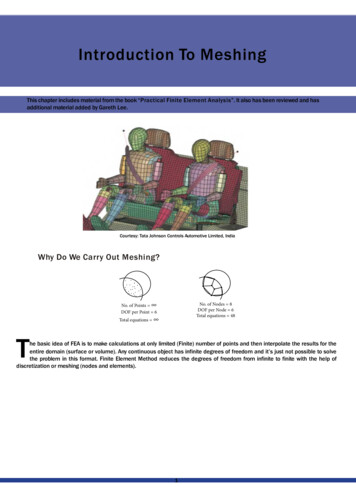
- Introduction To Meshing -Introduction To MeshingThis chapter includes material from the book “Practical FiniteFinit Element Analysis”. It also has been reviewed and hasadditional material added by Gareth Lee.Courtesy: Tata Johnson Controlsols Automotive Limited, IndiaWhy Do We Carry Out Meshing?No. of Points DOF per Point 6No. of Nodes 8DOF per Node 6Total equations 48Total equations he basic idea of FEA is to make calculations at only limited (Finite)(Fini number of points and then interpolate the results for theentire domain (surface or volume). Any continuous object has infinite degrees of freedom and it’s just not possible to solvethe problem in this format. Finite Element Method reduces the degrees of freedom from infinite to finite with the help ofdiscretization or meshing (nodes and elements).1
- Introduction To Meshing -Types Of ElementsElements1D2D3DOtherMidsurfaceyztxt - thickness of platet/2x y, zx , z yx y zOne of the dimensions isvery large in comparison tothe other twoElement shape – lineAdditional data from user remaining two dimensionsi.e. area of cross sectionElement type – rod, bar,beam, pipe, axisymmetricshell, etcPractical applications - Longshafts, beams, pin joint, connection elements, etc.Two of the dimensions arevery large in comparison tothe third oneElement shape – quad, triaAdditional data from user-remaining dimension i.e.thicknessElement type – thin shell,plate, membrane, planestress, plane strain, , axisymmetric solid, etc.Practical applications-Sheet metal parts, plasticcomponents like an instrument panel ,etc.All dimensions are comparableElement shape – tetra,penta, hex, pyramidAdditional data from user– noneElement type – solidPractical applications- Transmission casing,engine block, crankshaft,etc.Mass – Point element, concentrated mass at the centerof gravity of thecomponent Spring –translational and rotationalstiffnessDamper - damping coefficientGap – Gap distance,stiff- ness, frictionRigid – RBE2, RBE3WeldHow To Decide The Element TypeElement type selectionGeometry size and shapeType of analysisTime allotted forprojectA. Geometry Size And ShapeFor an analysis, the software needs all three dimensions defined.fined. It can not make calculations unless the geometry is definedcompletely (by meshing using nodes and elements).The geometry can be categorized as 1D, 2D, or 3D based on the dominant dimensions and then the type of element is selectedaccordingly.1D Element: Used for geometries having one of the dimensions that is very large in comparison to the other two.5101000x y, z1000 5, 10YXZThe shape of the 1D element is a line. When the element is creatted by connecting two nodes, the software knows about only oneout of the 3 dimensions. The remaining two dimensions, the area of the cross section, must be defined by the user as additionalinput data and assigned to the respective elementsPractical example: Long shaft, rod, beam, column, spot welding, boltedboljoints, pin joints, bearing modeling, etc.2
- Introduction To Meshing -2D Element: Used when two of the dimensions are very large in comparison to the third one.2300500Y500, 300 10 mmx, z yXZ2D meshing is carried out on a mid surface of the part. 2D elements are planar, just like paper. By creating 2D elements, thesoftware knows 2 out of the 3 required dimensions. The third dimension, thickness, has to provided by the user as an additionalinput data.Why Is 2D Meshing Carried Out On A Mid Surface?Mathematically, the element thickness specified by the user is assigned half on the element top and half on the bottom side.Hence, in order to represent the geometry appropriately, it is necessarynecessa to extract the mid surface and then mesh on the midsurface.Midsurfacett/2t - thickness of platePractical example: All sheet metal parts, plastic components likee instrument panels, etc. In general, 2D meshing is used for partshaving a width / thickness ratio 20.Limitations Of Mid Surface And 2D Meshing2D meshing would lead to a higher approximation if used for- variable part thickness- surfaces are not planner and have different featureseatures on two sides.3
- Introduction To Meshing -3D Element: used when all three dimensions are comparable100Y200X50x y z100 200 50ZPractical examples: Transmission casing, clutch housing, engine block,block connecting rod, crank shaft etc.Tractor Components MeshImage Source: Altair Calendar 2005Courtesy : Mahindra and Mahindra Ltd., Tractor DivisionB. Based On The Type Of AnalysisStructural and fatigue analysis - Quad, hex elements are preferrederred over trias, tetras and pentas.Crash and nonlinear analysis – Priority to mesh flow lines and brick elements over tetrahedron.Mold flow analysis – Triangular element are preferred over quadrilauadrilateral.Dynamic analysis – When the geometry is borderline between the classification of 2D and 3D geometry, 2D shell elements arepreferred over 3D. This is because shell elements being less stifferer captures the mode shapes accurately and with a fewer numberof nodes and elements.C. Time Allotted For ProjectWhen time is not a constraint, the appropriate selection of elements, mesh flow lines, and a good mesh quality is recommended.Sometimes due to a very tight deadline, the analyst is forced to submit the report quickly. For such situations1.Automatic or batch meshing tools could be used insteadead of time consuming but structured and good quality providingmethods.2. For 3D meshing tetras are preferred over hexas.3. If the assembly of several components is involved then only the critical parts are meshed appropriately. Other partsare either coarse meshed or represented approximatelyely by 1D beams, springs, concentrated mass, etc.4
- Introduction To Meshing -Can We Solve The Same Problem Using 1D, 2D And 3D ElementsIs it not possible to use 3D elements for long slender beams (1D geometry), for sheet metal parts (2D geometry), and 2D shellelements for representing big casting parts ?The same geometry could be modelled using 1D, 2D, or 3D elements. What matters is the number of elements and nodes (DOF),the accuracy of the results, and the time consumed in the analysis.For example, consider a cantilever beam with a dimension of 250 x 20 x 5 mm that is subjected to a 35 N force:1D beam modelN 2 E 1Total DOF 6 x 2 12N 909 E 800Total dof 909 x 6 54542D shell mesh3D Tetra meshN 17,448 E 9,569Total dof 17,448 x 3 44.214.215
- Introduction To Meshing -How To Decide Element Length Based on previous experience with a similar type of problem (successful correlation with experimental results). Type of analysis: Linear static analysis could be easily carried out quickly with a large number of nodes and elements,but crash, nonlinear, CFD, or dynamic analysis takes a lott of time. KeepingKcontrol on the number of nodes andelements is necessary. Hardwareconfiguration and graphics card capacity of the availableailable computer. An experienced CAE Engineer knows thelimit of the nodes that can be satisfactorily handled with the givengihardware configuration.Suppose you are a part of a newly formed CAE group (no clear guidelines are available, and there is no experienced person in thegroup): In the first run, accept the default element length. Mesh with the basic rules of thumb discussed in this book. Then run theanalysis and observe the high stress regions. Remesh the localized areas of high stress (with smaller element length) and solveagain. Compare the difference in the original and the new results.results Continue the process until convergence is achieved (5 to 10%difference in strain energy / maximum stress value).How To Start Meshing1) Spend A Sufficient Amount Of Time Studying TheGeometryA common observation is that CAE engineers start meshing immediately,immediawithout properly understanding the geometry and payingattention to all of the requirements and instructions provided. ObservingObsethe geometry several times and thinking about it fromall angles is strongly suggested. Mental visualization of the steps is the first step in the right direction of creating a good meshing.2) Time EstimationNow a days the trend is towards the client or boss specifying the estimatedestima time for a given job to the service provider or subordinate.Sometimes it is decided based on a mutual understanding. A time estimation is very relative and one can find a lot of differencesin estimation by different engineers (as much as 2 to 3 times). Usually a less experienced person will estimate more time. Alsoif someone is handling the job for the first time, then he/she will require more time. If similar kinds of jobs are given to the sameengineer again and again, the meshing time would reduce drastically.drasticall3) Geometry CheckGenerally CAD data is provided in *.igs format. Geometry cleanup is an integral part of the meshing activity. CAE engineers shouldat least have the basic knowledge of CAD. Before starting the job, the geometry should be carefully checked for: Free edges Scar lines Duplicate surfaces Small fillets Small holes Beads Intersection of parts (assembly of components)If suppressing fillets, small holes, beads, or the generation of a mid surface is required for meshing, then why isn’tthe CAD data provided in the way needed for CAE by the CADAD engineers?Yes, theoretically that would be an ideal situation, but practically everyone works with a very tight schedule and target dates.CAD data is generated keeping in mind the final drawing to be released for manufacturing. The same CAD model is providedsimultaneously to the tools and jig /fixture manufactures, vendors,s, purchase engineers, and CAE engineers, etc.The simplification required for a FEA is understood better by a CAE engineer than a CAD engineer. All meshing software providesspecial tools for geometry cleanup and simplification, which are usually much faster than CAD software. Many times, for complicatedgeometry, surfacing operations fail in CAD software and it could be easily handled by the CAE engineer by avoiding the geometryand generating the mesh using manual or special meshing operations.operations6
- Introduction To Meshing -4) Symmetry Check Complete part symmetryMeshing only a quarter of the platee and reflecting it twice is advisable. Sub-part symmetry, repetition of features, and the copy/pastee commandMeshing the highlighted 22.5º portion and then using reflection and rotation would lead to a faster mesh as well as the samestructure of elements and nodes around the critical areas (holes).5 ) Selection Of Type Of ElementsIn real life, we rarely use only one type of element. It is usually a combination of different types of elements (1D, 2D, 3D, andothers).In the above figure, the handle of the bucket is modelled by beam (1D) elements, the bucket body uses shell (2D) elements, andthe connection between the handle and the bucket body throughough RBE2 (rigid) elements.7
- Introduction To Meshing -6) Type Of Meshing Geometry based – The mesh is associated to the geometry. If the geometry is modified, the mesh will also getupdated accordingly (automatically). The boundary conditions could be applied on the geometry like a surface oredge, etc. FE based – The mesh is non associative. The boundary conditions are applied on the elements and nodes only.7) Joint Modelinga.Special instructions for bolted joints (specific construction around holes)b.Spot and arc weldc.Contact or gap elements and the requirement of the same pattern on 2 surfaces in the contactd.Adhesive joint8) Splitting The JobWhen there is little time or when engineers in other group are sitting idle, then the job could be split among several engineers byproviding a common mesh on the interfaces.Meshing TechniquesTime requiredfor meshingAutomatic /BatchMapped(or Interactive)i (intermediatei.e. more thanauto but less thanmanual)Manual (Specialcommands: Spline,Ruled, Drag /extrude, Spin / rotateetc.)hGeometry requiredNo. of nodes andelementsgeneratedUser friendlinessUser’s control overthe meshStructural mesh(flow lines)Experience orskill requiredPatienceXh ih ii hi h hhi i(specially for brick/ hex)Batch meshing / Mesh adviser – Now a days, all software providevide special programs for automatic geometry clean up and meshingwith little or no interaction from the user. The user has to specify all the parameters like minimum hole diameter, minimum filletradius, average and minimum element length, quality parameterrs, etc. and the software will run a program to produce the bestpossible mesh by fulfilling all or most of the specified instructions.instructions Though these programs are still in the initial stage and for manyapplications the output is not acceptable, the research is in progressogress and its performance will surely improve in the coming years.8
- Introduction To Meshing -Automatic mesh vs. mapped / interactive / manual meshNodes 1400,400, Elements 1309Automaticomatic meshingNot acceptableNodes 1073,73, Elements 982Mapped meshingMeshing In Critical AreasCritical areas are locations where high stress locations will occur.occu Dense meshing and structured mesh (no trias / pentas) isrecommended in these regions. Areas away from the critical area are general areas. Geometry simplification and coarse mesh ingeneral areas are recommended (to reduce the total DOFs and solution time).How Would I Know About The Critical Areas Before Carryingrying Out An Analysis?After going through a previous analysis of a similar part (carried out by your colleague or a senior in the group) one can get a fairlygood idea about the probable locations of the high stress. But suppose there is no past record and you are doing it for the firsttime, then run the analysis with a reasonable element length and observe the results. High stress regions are critical and couldbe remeshed with a smaller element length in the second run.9
- Introduction To Meshing -Rules for modeling holes and filletsCritical areaGeneral areaMinimum 12 elements around the hole4 to 6 elementsMinimum 3 elements on fillet.Suppress small fillets, 1 element for large fillets.Mesh transition techniques and flow lines1 to 31 to 32 to 42 to 41 to 21 to 2 x 2Mesh Display Options1. Shell Mesha. Mixed mode: Geometry – wireframe, Mesh - shadedThis is the most common and preferred way of wororking.10
- Introduction To Meshing -b. Line mode: Geometry and Mesh – both wireframeThis mode is preferred for brick meshing, foror internalinmesh adjustment / modifications.c. Solid: Geometry and Mesh – both shadedThis mode is not preferred for regular meshing but is very useful after the completion of the job. It helps to check the meshdeviation from the geometry and to find the kinks or abrupt changes in the mesh.11
- Introduction To Meshing -2. Brick Mesha. Line mode optionsAll faces displayFree faces displayThe figure on the left is used for viewing the internal details while the figure on the right is used for checking free faces inside themesh.b. Shading mode1. Shaded2. Shaded, no mesh lines3. Shaded and shrink option activatedThe solid view is commonly used during regular meshing. The shaded view is used for checking the kinks or deviation of the meshfrom geometry and the shrink view is used for checking for free faces and for missing or extra 1D elements on the edge of theelement.Understanding Element BehaviorTo successfully complete a finite element analysis, you must understand the behavior of various types of elements. A deeptheoretical knowledge of element formulations is not necessarily required although a fundamental knowledge of how eachelement type behaves is essential in the selection of the appropriaopriate element type(s) which will lead to proper interaction withapplied loads and boundary conditions.Finite element models consisting of a single element are one methodmof studying the mechanics of elements. The inputs andoutputs can be studied in detail and compared to solid mechanics solutions. This method is useful for understanding the sign andnaming conventions used by a particular solver.The following diagrams depict single element models, each with several load cases applied in conjunction with a minimum set ofboundary conditions. Adding more than the required boundary conditions can be used to learn even more about element behavior.DOFs are important because they dictate the ability of the elementslements to model a given problem and also dictate whether or notelements are compatible with each other. Further discussion on element compatibility will follow.12
- Introduction To Meshing -Rod ElementExample of rod elementNodes2nodesDOFs3 or 6degrees of freedom per nodeBeam ElementExample of beam elementNodes2nodesDOFs6degrees of freedom per node13
- Introduction To Meshing -Shell ElementExample of shell elements (CTRIA3, CQUAD4, CTRIA6, CQUAD8)CQFirst Order4 or 3nodesSecond Order6 or 8nodesDOFs6degrees of freedom per nodeSolid ElementExample of tetrahedron, pyramid, penta and hexa elementsFirst Order4, 5, 6, 8nodesSecond Order8, 12, 15, 20nodesDOFs3degrees of freedom per nodeHigher Order ElementsHigher order elements are those with one or more mid-side nodes,es, or geometry based elements, such as p-version elements. Thesetypes of elements offer the benefits of ease of modeling and a higher degree of accuracy per element. P-version type elementsalso have a built-in ability to check convergence by increasing the integration level although it is more difficult to understand theirfundamental behavior.14
- Introduction To Meshing -Higher order elements give rise to issues such as the sophisticatedsophisticamethods required to apply pressure to the face of a shellelement. The required distribution of nodal loads to accomplishplish the same resultant force (F P*A) on a 4 -node and an 8-nodeshell element is shown below.Consistent pressure loads for shells (F P x A)Most codes handle these details, but you should understand these and the other fundamentals of higher order elements to avoidconfusion. Higher order elements are most often used in 3-D solid modeling because the potential to reduce modeling effort andthe number of elements required to capture the geometry is greater.greaSolution time is not often reduced however because theglobal stiffness matrix is based on nodal DOF in the model.Plane Stress And Strain ElementPlane stress:σ z τ yz τ zx 0 ε z 0Athin planar structure with constant thickness and loading within the plane of the structure for example:Plane strain:ε z γ yz γ zx 0 σ z 0A long structure with a uniform cross section and transverse loading along its length , for example:15
- Introduction To Meshing -11.Element SelectionElement selection is based on the type of problem you want to run, boundary conditions, geometry considerations, and resultsrequired. Most problems can be solved many different ways and there is no “right” answer to the question of element selection,but making a good choice can reduce effort, computer time, and errors in the results. Often the solver you choose to solve theproblem will have limitations for some element types and not for othersorestricting element selection.Masses (0D elements)Masses are point load masses that are generally used to represent attached structures at their centroids. This is an extremelygood way to represent otherwise complex structures when the detailedtailed is not required.Beams (1D elements)Beams are characterized by long and slender members, such as a space frame or a formula racing suspension. Bridge membersare also good examples of beams or spars. Some examples of 1DD elements are listed below: Rods Spars Beams Welds RigidsBeams are very useful because of the flexibility in modeling complplex cross-sections without modeling the geometry, but the burdenof maintaining the detailed information is upon the user. In addition very accurate stress and deflection results are achievablewith beam elements, but the visualization of the results is sometimestimes difficult. Rods and Spars are essentially 2D beams and aregreat for in plane problems. Welds and rigids are used for definingfining constraint equations between nodes. Generally this results inan independent node and a dependent node(s) that form a set of equations that are placed in the stiffness matrix.Plates (2D elements)Plates are 2D elements that represent 3D space by assuming an infinite depth, fixed depth, or axisymmetric geometry. They havea reduced stiffness matrix and therefore reduced solution time with no loss in accuracy if the assumptions for the element hold.Shells (2.5D elements)Shells are essentially 2D elements that represent 3D space, thus the term 2.5D. Shells are excellent for thin 3D structures, suchas body panels, sheet metal, injection molded plastic or any part that can be described as having a thickness that is small relativeto its global dimensions. Deflections are given at the nodes, but stresses can be found at the upper and lower surfaces as well asat the midplane. This gives the analyst the ability to extract membrane effects versus bending effects in the results.Solids (3D elements)Solid elements are generally used for 3D structures not fitting intto the shell description. Castings, forgings, blocky structures, andvolumes are all good examples of 3D solid element structures. Solid elements have the benefit of eliminating many assumptionsfound in the other element types but are generally more difficult too model.12.Mesh Density And Solution ConvergenceergenceMesh density and solution convergence are closely related and the factors which determine that relationship can be controversial.In an effort to meet specific time and accuracy requirements, trade-offstradeinvolving modeling time, accuracy, computation time, andcost must be made.The correct mesh, from a numerical accuracy standpoint, is one that yields no significant differences in the results when a meshrefinement is introduced. Although this concept may sound simplistic,plistic, many factors must be considered. Mesh refinements mustaccurately represent the problem in question if they are to be used in the analysis. Mesh refinements by simple splitting ofelements can be misleading unless the newly created nodes conformconclosely to the original geometry. As refinement progresses,the original element selection must retain its significance. For example,exaa shell model can be refined to the point that it loses itsvalidity in the area of interest, creating a need for a solid element model.16
- Introduction To Meshing -Determining a mesh density is facilitated by following a fewew basic guidelines.Geometric Detail RequiredDetermine the smallest geometric detail(s) that must be captured in the model to obtain the results. A very sharp radius maycause a stress concentration, but at the same time, it may not be in a load bearing component of the assembly. The modelingrequired to capture this detail may require a separate local analysis after an analysis of the overall structure or component hasbeen conducted.Design Detail AvailableObserve the degree of detail in the available design data. If the design data is preliminary or incomplete, or if you are using finiteelement analysis to help define the design, it is best to keep models simple. Take care not to oversimplify models to the point thatfactors under investigation are missed.If the design is considered complete and a final verification is being conducted, include as much detail and mesh refinement(including re-mesh iterations for accuracy checks) as time permits.permitsComparisons To Previous WorkIf you will be comparing your work to other analysis results foror the same or similar components, consider using a previouslyused mesh density which is similar. Consider correlations establishedablished with the testing of past models but be prepared to identifyimproper boundary conditions or load applications, poor modeling techniques, or inadequate mesh density. If such testing flawsare discovered, establish a new standard. Do not accept the workk of others until it is fully understood.Expected Deformed ShapeDetermine possible deflection shapes and the mesh densities requiredreto capture them. Estimate the maximum deflection areasand areas of curvature inflection. Observe whether nodal densityensity follows the deflection pattern closely. Note the pattern shownbelow.Deformed shape with element densityChecks Of ConvergenceIf you plan to do a convergence check, consider performing at least one refinement of the model after the first run. If neighboringelements display large differences in stress, the gradient was probablyobably not captured in these areas, therefore some refinement isrecommended.New techniques for automatically computing convergence by seveveral criteria are available on certain codes or can be customizedby the user. Some computer codes will also automatically re-meshmesh nonconverged portions of a model. These techniques aredependent on the load cases and will provide different meshes foror different load cases.The p-version accomplishes refinement by numerically increasing the complexity of each element or nonconverged elements onsubsequent re-runs. All automated techniques require that the model be set up to “near perfect” or the convergence may focus onsmall details that are irrelevant to the specific problem or have notot been modeled with elements, boundary conditions or loads thathave a natural converged solution. It is best to set up a problem so that there is a chance for convergence even if you do not intend17
- Introduction To Meshing -to perform a convergence test. Below is an example of a flat structure that will converge if modeled in shells but will not convergeif modeled “more accurately” with solids. Since the shells do not sense stress in the direction of the load, they will converge to theshell theory solution. The solids will attempt to resolve the “point load” and the stresses will go higher and higher as the elementsunder the load decrease in size.Deflection Or StressIn most cases, far fewer elements are necessary if only deflection or stiffness information is required. Even fewer elements canbe used if only the deflection under the load is to be studied. For instance, one beam or one shell can estimate the deflection of acantilever beam of rectangular section. It may, however, take dozens of shell or solid element to capture the stress at the boundaryin a simple cantilever beam. If there is a high gradient of stress ovver a large area, for example, a web in the corner of a frame, manyelements may be required to get the proper deflection.Web stiffenerstiAreas Of ConcernDetermine the areas of concern. If you have a known issue in the lab or the field you will certainly want some detail in theseareas. If time is limited, you may want to focus only in these areas and use rough approximations else where. If you have no priorknowledge of the component of system and a history search has not turned up any clues, you may have to make a very uniformmesh and refine areas that respond to the applied loads. Use yourour engineering sense to predict the areas that are prone to trouble.18
- Introduction To Meshing -Some typical areas of concern are listed below: Tight radii Points of load application Boundary points Attachment points Narrow sections Abrupt change in sectionElement TypesMesh density is very dependent on the selection of element types therefore select the element type that is appropriate to solveyour problem. Determine whether the structure should be considered as a shell type or if a full 3D model is needed to captureeither the state of stress, geometry, or local deflections.For example, engine blocks can be modeled with shells and beams when stiffness or dynamics is the only consideration. However,the stresses cannot be studied since this component is a 3-D solid when stress becomes a consideration. The time differenceto model an engine in solids versus shells and beams can be enormous.enormous Below it is a list of Rules of Thumb regarding elementselection: Do NOT mix trias and quads whenever possible and if required place trias in areas of non-concern Use all trias for back-to-back comparisons when youou have determined trias are adequate to your solution - don’tcompare a quad model with a refined tria model. Use elements of consistent size whenever possible Do NOT combine shells and solids or beams and shells/solids without first understanding all the assumptions andimplications to your solution Model solid parts with solid elements Model thin plate structures with shell elements ( thickness 10-20 x Edge length) Understand all assumptions for the element type you havehselected Do NOT use degenerated elements unless required Do NOT mix tetrahedral elements with other element types and, if required, place outside areas of concern Use tetrahedral elements when the effort required to model hexahedral elements is excessive (this can run into weeksof effort versus days for tetras) Use beam elements when shells or solids require excessicessive modeling time and effortBeam elements can be used effectively in beam-like structures or for fasteners and connections. However, due to the complexity ofemploying beam elements, they are probably the most misused elements in the family of elements. The following considerationsmake using beam elements a difficult process to perform successfully.successfull Shear center Warping constraint Length to depth ratio Shear deflection Complex state of stress near end conditions Visualizing both the input and the output of beam analysisStress results for complex beam sections are only good for global type values computed by classical beam methods. Beams of19
- Introduction To Meshing -circular cross section are an exception because
-Introduction To Meshing HowToDecide Element Length Based on previous experience with asimilar type of problem (successful Type of analysis: Linear static analysis could be easily carried out