Transcription
Dell Precision T7500 Service ManualWorking on Your ComputerAdding and Replacing PartsSpecificationsDiagnosticsAbout MemoryAbout Your System BoardSystem SetupNotes, Cautions, and WarningsNOTE: A NOTE indicates important information that helps you make better use of your computer.CAUTION: A CAUTION indicates potential damage to hardware or loss of data if instructions are notfollowed.WARNING: A WARNING indicates a potential for property damage, personal injury, or death.If you purchased a Dell n Series computer, any references in this document to Microsoft Windows operating systemsare not applicable.Information in this document is subject to change without notice. 2009-2010 Dell Inc. All rights reserved.Reproduction of this material in any manner whatsoever without the written permission of Dell Inc. is strictly forbidden.Trademarks used in this text: Dell, the DELL logo, and Dell Precision are trademarks of Dell Inc.; Intel and Xeon are registered trademarks ofIntel Corporation; Bluetooth is a registered trademark owned by Bluetooth SIG, Inc. and is used by Dell under license; Blu-ray Disc is atrademark of the Blu-ray Disc Association; Microsoft, Windows, Windows Server, MS-DOS, Aero, Windows Vista. and the Windows Vista startbutton are either trademarks or registered trademarks of Microsoft Corporation in the United States and/or other countries.Other trademarks and trade names may be used in this document to refer to either the entities claiming the marks and names or theirproducts. Dell Inc. disclaims any proprietary interest in trademarks and trade names other than its own.Model DCDOFebruary 2010 Rev. A01
Working on Your ComputerDell Precision T7500 Service ManualBefore Working Inside Your ComputerRecommended ToolsTurning Off Your ComputerAfter Working Inside Your ComputerBefore Working Inside Your ComputerUse the following safety guidelines to help protect your computer from potential damage and to help to ensure yourpersonal safety. Unless otherwise noted, each procedure included in this document assumes that the following conditionsexist:You have performed the steps in Working on Your Computer.You have read the safety information that shipped with your computer.A component can be replaced or—if purchased separately—installed by performing the removal procedure inreverse order.WARNING: Before working inside your computer, read the safety information that shipped with yourcomputer. For additional safety best practices information, see the Regulatory Compliance Homepageat www.dell.com/regulatory compliance.CAUTION: Only a certified service technician should perform repairs on your computer. Damage due toservicing that is not authorized by Dell is not covered by your warranty.CAUTION: To avoid electrostatic discharge, ground yourself by using a wrist grounding strap or byperiodically touching an unpainted metal surface, such as a connector on the back of the computer.CAUTION: Handle components and cards with care. Do not touch the components or contacts on a card.Hold a card by its edges or by its metal mounting bracket. Hold a component such as a processor by itsedges, not by its pins.CAUTION: When you disconnect a cable, pull on its connector or on its pull-tab, not on the cable itself.Some cables have connectors with locking tabs; if you are disconnecting this type of cable, press in onthe locking tabs before you disconnect the cable. As you pull connectors apart, keep them evenlyaligned to avoid bending any connector pins. Also, before you connect a cable, ensure that bothconnectors are correctly oriented and aligned.NOTE: The color of your computer and certain components may appear differently than shown in this document.To avoid damaging your computer, perform the following steps before you begin working inside the computer.1. Ensure that your work surface is flat and clean to prevent the computer cover from being scratched.2. Turn off your computer (see Turning Off Your Computer).CAUTION: To disconnect a network cable, first unplug the cable from your computer and then unplugthe cable from the network device.3.5.6.7.Disconnect all network cables from the computer.Disconnect your computer and all attached devices from their electrical outlets.Press and hold the power button while the system is unplugged to ground the system board.Remove the computer cover (see Removing and Replacing the Computer Cover).CAUTION: Before touching anything inside your computer, ground yourself by touching an unpaintedmetal surface, such as the metal at the back of the computer. While you work, periodically touch anunpainted metal surface to dissipate static electricity, which could harm internal components.Recommended ToolsThe procedures in this document may require the following tools:Small flat-blade screwdriver
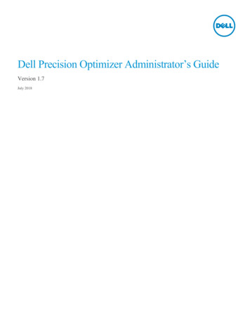
Phillips screwdriverSmall plastic scribeFlash BIOS update program CD (see the Dell Support website at support.dell.com)Turning Off Your ComputerCAUTION: To avoid losing data, save and close all open files and exit all open programs before you turnoff your computer.1. Shut down the operating system:In Windows Vista:, then click the arrow in the lower-right corner of the Start menu as shown below, and thenClick Startclick Shut Down.In Windows XP:Click Start Turn Off Computer Turn Off.The computer turns off after the operating system shutdown process is complete.2. Ensure that the computer and all attached devices are turned off. If your computer and attached devices did notautomatically turn off when you shut down your operating system, press and hold the power button for about 6seconds to turn them off.After Working Inside Your ComputerAfter you complete any replacement procedure, ensure you connect any external devices, cards, and cables before turningon your computer.1. Replace the computer cover (see Removing and Replacing the Cover).2. Connect any telephone or network cables to your computer.CAUTION: To connect a network cable, first plug the cable into the network device and then plug it intothe computer.3. Connect your computer and all attached devices to their electrical outlets.4. Turn on your computer.5. Verify that the computer works correctly by running the Dell Diagnostics. See Dell Diagnostics.
Adding and Replacing PartsDell Precision T7500 Service ManualCoverChassis Intrusion SwitchBatteryDrives BezelHard DriveHard-drive FanHard-drive CageOptical DriveFront Fan AssemblyRear FanMemory ShroudMemoryExpansion CardsHeat Sink and ProcessorProcessor FanDual Processor Riser (Optional)Dual Processor Riser GuideI/O PanelPower SupplySystem Board
SpecificationsDell Precision T7500/T7500n Service ManualProcessorsDrivesSystem InformationConnectorsMemoryControls and LightsVideoPowerAudioPhysicalExpansion BusEnvironmentalNOTE: Offerings may vary by region. For more information regarding the configuration ofyour Tablet-PC, click Start(or Start in Windows XP) Help and Support, and thenselect the option to view information about your Tablet-PC.ProcessorProcessor typesDual-Core Intel Xeon Processor 5500seriesQuad-Core Intel Xeon Processor5500 seriesSystem InformationSystem chipsetIntel 5500/5520Data bus width64 bitsMemoryMemory module connectorsSixTwelve with optional riserMemory module capacities1 GB, 2 GB, 4 GB, 8 GB and 16 GBMemory typeDDR3 1066 MHz SDRAMDDR3 1333 MHz SDRAM(DDR3 800 MHz capable)Minimum memory1 GBMaximum memory96 GB192 GB with optional riserVideoVideo type:DiscretePCI Express 2.0 x16 (2 slots)NOTE: Support for two full height, fulllength graphics cards using the PCIe x16graphics card slot.AudioAudio typeAnalog Devices ADI1984A
Expansion BusBus typePCI Express 2.0PCI 2.3PCI-X 2.0ASATA 1.0 and 2.0eSATA 2.0SASUSB 2.0Bus speed133 MB/s (PCI)x1-slot bidirectional speed - 500 MB/s(PCI Express)x16-slot bidirectional speed - 8 GB/s(PCI Express)1.5 Gbps and 3.0 Gbps (SATA)480-Mbps high speed, 12-Mbps fullspeed, 1.2 Mbpslow speed (USB)Two PCI Express 2.0 x16 slots (video)Connector pins164 pinsConnector data width (maximum)16 PCI Express lanes (each direction)Two PCI Express 2.0 x8 slots (physicalx16 connector)Connector pins164 pinsConnector data width (maximum)8 PCI Express lanes (each direction)One PCI Express 2.0 x4 slot (physicalx16)Connector pins164 pinsConnector data width (maximum)4 PCI Express lanes (each direction)One PCI SlotConnector pins120 pinsConnector data width (maximum)32 bitsOne PCI-X SlotConnector pins188 pinsConnector data width (maximum)64 bitsDrivesExternally accessibleFour 5.25 inch drive bays (can support3.5 inch flex bay)Internally accessibleFour 3.5 inch drive baysAvailable devicesUp to three of the following 5.25 inchdevices: SATA DVD ROM, SATA DVD /RW super multi drive/Blu-ray driveOne 3.5-inch USB media card reader orone 3.5 inch Floppy Disk DriveUp to five 3.5-inch SATA or four SAShard drivesConnectorsExternal connectors:Video(Depending on video card)DVI connectorDisplay port
Network adapterRJ-45 connectorUSBUSB 2.0 compliantTwo internal connectorsTwo in the frontSix in the backSerialOne 9-pin connector; 16550CcompatibleParallelOne 25-pin connectoreSATAOne 7-pin eSATA connectorAudioStereo support integrated (5.1 channelsupport)NOTE: 5.1 channel support comes froman add-in card onlyPS/2Two 6-pin mini-DIN connectorsSystem board connectors:Serial ATAThree 7-pin SATA connectorsSASFour 7-pin SAS connectorsInternal USB deviceTwo 10-pin connector (supports twoUSB ports)Fans:Hard Disk Drive fanOne 5-pin connectorFront fanOne 7-pin connectorRear fanOne 5-pin connectorCard cage fanOne 7-pin connectorPCIOne 120-pins connectorPCI-XOne 188-pins connectorPCI Express x16Two 164-pin connectorsPCI Express x8Two 164-pin connectors (physical x16connector)PCI Express x4One 164-pin connectorFront panel controlOne 10-pin connectorFront panel USBOne 10-pin connectorFront panel audio HDA headerOne 10-pin connectorProcessorOne connectorSecond connector on optional riserMemorySix 240-pin connectorsSix 240-pin connectors on optional riserProcessor PowerOne 4-pin connectorSecond 4-pin connector on optional riserPowerOne 24-pin connectorControls and LightsFront of the computerPower buttonPush buttonPower lightAmber light — Solid amber indicates aproblem with an installed device;blinking amber indicates an internalpower problemGreen light — Blinking green in sleep
state; solid green for power-on stateDrive activity lightGreen light — A blinking green lightindicates the computer is reading datafrom or writing data to the hard drive orCD/DVDNetwork link lightGreen light — Solid green indicatesconnection to an active networkOff (no light) — System is not connectedto a networkBack of the computerLink integrity light (on integratednetwork adapter)Off — The computer is not detecting aphysical connection to the networkGreen — A good connection at 10Mbsexists between the network and thecomputerOrange — A good connection at 100Mbsexists between the network and thecomputerYellow — A good connection at 1000Mbsexists between the network and thecomputerNetwork activity light (on integratednetwork adapter)Yellow blinking lightPowerDC power supply:Wattage1100 WVoltage100–240 VAC, 50–60 Hz, 12.0 ACoin-cell battery3V CR2032 lithium coin cellPhysicalHeight56.50 cm (22.25 inches)Width21.60 cm (8.50 inches)Depth55.30 cm (21.80 inches)Weightat least 24.90 kg (55 lbs)EnvironmentalTemperature range:Operating10 to 35 C (50 to 95 F)Storage-40 to 65 C (-40 to 149 F)Relative humidity (maximum):20% to 80% (noncondensing)Maximum vibrationOperating5 to 350 Hz at 0.0002 G²/HzStorage5 to 350 Hz at 0.0002 G²/HzMaximum shockOperating40 G /- 5% with pulse duration of 2msec /- 10% (equivalent to 51 cm/sec[20 in/sec])Storage105 G /- 5% with pulse duration of 2msec /- 10% (equivalent to 127cm/sec [50 in/sec])Altitude (maximum):
Operating-15.2 to 3048 m (-50 to 10,000 ft)Storage-15.2 to 10,668 m (-50 to 35,000 ft)Airborne contaminant levelG2 or lower as defined by ISA-S71.041985
DiagnosticsDell Precision T7500 Service ManualDell DiagnosticsPower Button Light CodesDiagnostic Light CodesPre-POST Diagnostic Light PatternsPOST Diagnostic Light PatternsBeep CodesDell DiagnosticsWhen to Use the Dell DiagnosticsIt is recommended that you print these procedures before you begin.NOTE: The Dell Diagnostics software works only on Dell computers.NOTE: The Drivers and Utilities disc is optional and may not ship with your computer.Enter system setup (see Entering System Setup), review your computer's configuration information, and ensure that thedevice you want to test displays in System Setup and is active.Start the Dell Diagnostics from either your hard drive or from the Drivers and Utilities disc.Starting the Dell Diagnostics From Your Hard Drive1. Turn on (or restart) your computer.2. When the DELL logo appears, press F12 immediately.NOTE: If you see a message stating that no diagnostics utility partition has been found, run the Dell Diagnosticsfrom your Drivers and Utilities disc.If you wait too long and the operating system logo appears, continue to wait until you see the Microsoft Windows desktop. Then shut down your computer (see Turning Off Your Computer), and try again.3. When the boot device list appears, highlight Boot to Utility Partition and press Enter .4. When the Dell Diagnostics Main Menu appears, select the test that you want to run.Starting the Dell Diagnostics From the Drivers and Utilities Disc1. Insert the Drivers and Utilities disc.2. Shut down and restart the computer.When the DELL logo appears, press F12 immediately.If you wait too long and the Windows logo appears, continue to wait until you see the Windows desktop. Then shutdown your computer and try again.NOTE: The next steps change the boot sequence for one time only. On the next startup, the computer bootsaccording to the devices specified in the system setup program.3. When the boot device list appears, highlight Onboard or USB CD-ROM Drive and press Enter .4. Select the Boot from CD-ROM option from the menu that appears and press Enter .5. Type 1 to start the menu and press Enter to proceed.
6. Select Run the 32 Bit Dell Diagnostics from the numbered list. If multiple versions are listed, select the versionappropriate for your computer.7. When the Dell Diagnostics Main Menu appears, select the test you want to run.Dell Diagnostics Main Menu1. After the Dell Diagnostics loads and the Main Menu screen appears, click the button for the option you want.OptionFunctionExpressTestPerforms a quick test of devices. This test typically takes 10 to 20 minutes and requires no interaction onyour part. Run Express Test first to increase the possibility of tracing the problem quickly.ExtendedTestPerforms a thorough check of devices. This test typically takes 1 hour or more and requires you to answerquestions periodically.CustomTestTests a specific device. You can customize the tests you want to run.Symptom Lists the most common symptoms encountered and allows you to select a test based on the symptom of theTreeproblem you are having.2. If a problem is encountered during a test, a message appears with an error code and a description of the problem.Write down the error code and problem description and follow the instructions on the screen.3. If you run a test from the Custom Test or Symptom Tree option, click the applicable tab described in thefollowing table for more information.TabFunctionResultsDisplays the results of the test and any error conditions encountered.ErrorsDisplays error conditions encountered, error codes, and the problem description.HelpDescribes the test and may indicate requirements for running the test.Configuration Displays your hardware configuration for the selected device.The Dell Diagnostics obtains configuration information for all devices from system setup, memory, andvarious internal tests, and it displays the information in the device list in the left pane of the screen. Thedevice list may not display the names of all the components installed on your computer or all devicesattached to your computer.ParametersAllows you to customize the test by changing the test settings.4. When the tests are completed, if you are running the Dell Diagnostics from the Drivers and Utilities disc, removethe disc.5. Close the test screen to return to the Main Menu screen. To exit the Dell Diagnostics and restart the computer,close the Main Menu screen.Power Button Light CodesThe diagnostic lights give much more information about the system state, but legacy power light states are alsosupported in your computer. The power light states are shown in following criptionPower is off, light is blank.Initial state of light at power up.Indicates system has power, but the POWER GOOD signal is not yet active.If the Hard Drive light is off, it is probable that the power supply needs to be replaced.If the Hard Drive light on, it is probable that an onboard regulator or VRM has failed. Look at thediagnostic lights for further information.Second state of the light at power up. Indicates the POWER GOOD signal is active and it is probable that
the power supply is fine. Look at the diagnostic lights for further information.BlinkingGreenSolidGreenSystem is in a low power state, either S1 or S3. Look at the diagnostic lights to determine which state thesystem is in.System is in S0 state, the normal power state of a functioning machine.The BIOS will turn the light to this state to indicate it has started fetching opcodes.Diagnostic Light CodesFour (4) single color lights are incorporated on the front control panel to serve as a diagnostic aid for troubleshootingsystems exhibiting No Post/No Video symptoms. The lights do NOT report runtime errors.Each light has two possible states of OFF or ON. The most significant bit is labeled with the number 1, and the other threeare labeled 2, 3, and 4, as you go down or across the LED stack. The normal operating condition after POST is for all fourlights to be ON and then turn off as the BIOS hands over control to the operating system.Pre-POST Diagnostic Light PatternsStateLight Pattern(1234)LightPowerStateDescription Light AssignmentState tem is not plugged into AC, PSU is not plugged intosystem board, or control panel not connected tosystem board.Pb0b1234-OffOffOffOffACPI S0;NormalOperationSystem is on with no failures detected. This is actuallya BIOS controlled state and is also S0e.Pb0c1234-OffOffOffOffACPI S1Windows Standby State.Pb11234-OffOffOffOffACPI S4 orS5Hibernate or Soft off. System plugged in, but eitherturned off or in Windows Hibernation 4-OffOffSolidSolidACPI S3Suspend to RAM Windows Standby 34-OffGreenOffGreen-ReservedReserved-
I S0,System on. BIOS not execution. This is the transitionhand off tostate to POST states.BIOS boardRegulatorFailureA power failure has been detected on a plug-incomponent such as VRM, Video Riser, or MemoryRiser.Pb101234-BlinkOffBlinkOffPSU FailurePSU may be bad or PSU cable may be crimpedcreating a short on a main power rail. (PS ONasserted, PS PWRGOOD not asserted)Pb111234-BlinkOffBlinkBlinkPSU CableFailureAll PSU cables may not be properly connected tosystem board. (PS ON asserted, missing a main latorFailureA power failure has been detected in one of theonboard system board regulators. This could be causedby a failed system board component or by a plug-indevice creating a short on a regulated power rail.(PS ON asserted, PS PWRGOOD asserted,SYS PWRGOOD dware detected a population incompatibility with acritical system component such as CPU, VRM, PSU, orMEMORY Pb151234-GreenGreenGreenGreen-ReservedReservedPOST Diagnostic Light PatternsAll POST codes except S0 are accompanied by a Solid Green Power light state. If the power light is not green, see PrePOST Diagnostic Light Patterns.StateLight Pattern(1234)LightStateStateDescription Name AssignmentState DescriptionS0a1234-OffOffOffOffOFFOFFPower light Off. No power is supplied to the system.S0e1234-OffOffOffOffONNormalOperation,ACPI S0Power light Solid Green. System has successfullybooted and is operating normally.S11234-OffOffOffSolidRCMSystem is inRecoveryModeBIOS checksum failure was detected and the system isnow in recovery mode.1- Off2- OffCPU configuration activity is in progress or a CPU
S23- Solid4- OffCPUCPUfailure was detected.S31234-OffOffSolidSolidMEMMemoryMemory subsystem configuration activity is in progress.Appropriate memory modules were detected but amemory failure has occurred.S41234-OffSolidOffOffPCIPCI devicePCI device configuration activity is in progress or PCIdevice failure was detected.S51234-OffSolidOffSolidVIDVideo CardVideo subsystem configuration activity in progress orvideo subsystem failure.S61234-OffSolidSolidOffSTOStorageStorage device configuration in progress or storagesubsystem failure.S71234-OffSolidSolidSolidUSBUSBUSB subsystem configuration activity in progress orUSB subsystem failure.S81234-SolidOffOffOffMEMMemoryMemory subsystem configuration activity is in progress.No memory modules were l system board failure detected.S101234-SolidOffSolidOffMEMMemoryMemory subsystem configuration activity is in progress.Memory modules have been detected but appear to beincompatible or in an invalid configuration.S111234-SolidOffSolidSolidPRVOther prevideoactivityIndicates routine system activity preceding ourceSystem resource configuration in idReservedReserved for future use. This pattern is beingconsidered to indicate the Visual Off state on theDimension systems.POVOther postvideoactivityIndicates routine system activity subsequent to videoinitialization.STDBoot handoffIndicates End of POST process. Lights are normally inthis state briefly as POST completes. Once the hand-offto the OS is done, the lights turn off and transition toS0e state.Beep CodesWhen errors occur during a boot routine that cannot be reported on the monitor, the computer may emit a beep code thatidentifies the problem. The beep code is a pattern of sounds: for example, one beep followed by a second beep, thenfollowed by a burst of three beeps (code 1-1-3) means that the computer was unable to read the data in nonvolatilerandom-access memory (NVRAM). If the system loses power and beeps constantly when you turn it back on, the BIOS isprobably corrupted.
System Beep U register test in progress2-4-31st 64 K RAM chip or data line failure - bit E1-1-3CMOS read/write test in progress or failure2-4-41st 64 K RAM chip or data line failure - bit F1-1-4BIOS ROM checksum in progress or failure3-1-1Slave DMA register test in progress or failure1-2-1Timer Test in progress or failure3-1-2Master DMA register test in progress or failure1-2-2DMA initialization in progress or failure3-1-3Master IMR test in progress or failure1-2-3DMA page register read/write test in progressor failure3-1-4Slave IMR test in progress or failure1-3-1RAM refresh verification in progress or failure3-2-2Interrupt vector loading in progress1-3-21st 64 K RAM test in progress or failure3-2-4Keyboard controller test in progress or failure1-3-31st 64 K RAM chip or data line failure (multibit)3-3-1CMOS power fail and checksum test in progress1-3-41st 64 K RAM odd/even logic failure3-3-2CMOS Config info validation in progress1-4-11st 64 K RAM address line failure3-3-3RTC/Keyboard controller not found1-4-21st 64 K RAM parity test in progress or failure3-3-4Screen memory test in progress or failure1-4-3Fail-safe timer test in progress3-4-1Screen initialization test in progress or failure1-4-4Software NMI port test in progress3-4-2Screen retrace tests test in progress or failure2-1-11st 64 K RAM chip or data line failure - bit 03-4-3Search for video ROM in progress2-1-21st 64 K RAM chip or data line failure - bit 14-2-1Timer tick interrupt test in progress or failure2-1-31st 64 K RAM chip or data line failure - bit 24-2-2Shutdown test in progress or failure2-1-41st 64 K RAM chip or data line failure - bit 34-2-3Gate A20 failure2-2-11st 64 K RAM chip or data line failure - bit 44-2-4Unexpected interrupt in Protected Mode2-2-21st 64 K RAM chip or data line failure - bit 54-3-1RAM test in progress or failure above address0FFFFh2-2-31st 64 K RAM chip or data line failure - bit 64-3-2No memory in Bank 02-2-41st 64 K RAM chip or data line failure - bit 74-3-3Interval Timer Channel 2 test in progress orfailure2-3-11st 64 K RAM chip or data line failure - bit 84-3-4Time-Of-Day Clock test in progress or failure2-3-21st 64 K RAM chip or data line failure - bit 94-4-1Super I/O chip failure2-3-31st 64 K RAM chip or data line failure - bit A4-4-4Cache test failure2-3-41st 64 K RAM chip or data line failure - bit B2-4-11st 64 K RAM chip or data line failure - bit C2-4-21st 64 K RAM chip or data line failure - bit D
About MemoryDell Precision T7500 Service ManualMemory ModulesSupported Memory ConfigurationsMemory SubsystemMemory SlotsMemory Population RulesWARNING: Before working inside your computer, read the safety information that shipped with your computer.For additional safety best practices information, see the Regulatory Compliance Homepage atwww.dell.com/regulatory compliance.Your computer uses 1066 MHz and 1333Mhz DDR3 unbuffered or registered ECC SDRAM memory. DDR3 SDRAM, or double-datarate three synchronous dynamic random access memory, is a random access memory technology. It is a part of the SDRAM familyof technologies, which is one of many DRAM (dynamic random access memory) implementations, and is an evolutionaryimprovement over its predecessor, DDR2 SDRAM.The primary benefit of DDR3 SDRAM is its ability to run its I/O bus at four times the speed of the memory cells it contains, thusenabling faster bus speeds and higher peak throughputs than earlier technologies. This is achieved at the cost of higher latency.Also, the DDR3 standard allows for chip capacities of 512 megabit to 8 gigabit, effectively enabling memory modules of maximum16 gigabyte in size.DDR3 memory comes with a promise of a power consumption reduction of 30% compared to current commercial DDR2 modules dueto DDR3’s 1.5 V supply voltage. This supply voltage works well with the 90 nm fabrication technology used for most DDR3 chips.Some manufacturers further propose to use "dual-gate" transistors to reduce leakage of current.The main benefit of DDR3 comes from the higher bandwidth made possible by DDR3’s 8 bit deep prefetch buffer, whereas DDR2’s is4 bits, and DDR’s is 2 bits deep.Memory ModulesStandardnameMemoryclockCycletimeI/O BusclockData transfers persecondModulenamePeak transferrateDDR3-1066133 MHz7.5 ns533 MHz1066 MillionPC3-85008533 MB/sDDR3-1333166 MHz6 ns667 MHz1333 MillionPC3-1060010667 MB/sSupported Memory ConfigurationsSingle Processor Memory ConfigurationsSize(GB)DIMMRanksDIMM1DIMM2DIMM33SR1 GB1 GB1 GB4SR1 GB1 GB1 GB1 GB4MR2 GB1 GB1 GB1 GB6SR2 GB2 GB2 GB8MR2 GB2 GB2 GB1 GB1 GB12SR2 GB2 GB2 GB2 GB2 GB2 GB12DR4 GB4 GB4 GB24DR4 GB4 GB4 GB4 GB4 GB4 GB24DR8 GB8 GB8 GB32MR8 GB8 GB4 GB4 GB4 GB4 GB48DR8 GB8 GB8 GB8 GB8 GB8 GB96QR16 GB16 GB16 GB16 GB16 GB16 GBDIMM4DIMM5DIMM6
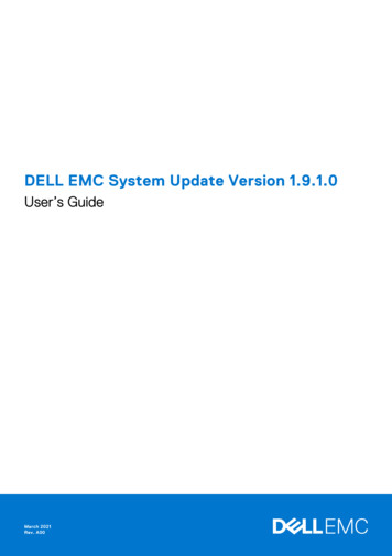
Dual Processor Memory M3MBDIMM43SR1 GB1 GB1 GB4SR1 GB1 GB1 GB1 GB6SR1 GB1 GB1 GB1 GB1 GB1 GB8MR2 GB1 GB1 GB2 GB1 GB1 GB12SR2 GB2 GB2 GB2 GB2 GB2 GB24DR4 GB4 GB4 GB4 GB4 GB4 GB24SR2 GB2 GB2 GB2 GB2 GB2 GB48DR8 GB8 GB8 GB8 GB8 GB8 GB48DR4 GB4 GB4 GB4 GB4 GB4 GB4 GB4 GB96DR8 GB8 GB8 GB8 GB8 GB8 GB8 GB128MR16 GB16 GB8 GB8 GB8 GB8 GB192QR(RHELONLY)16 GB16 GB16 GB16 GB16 GB16 GB2 GBMBDIMM52 GBMBDIMM62 M5RiserDIMM62 GB2 GB2 GB4 GB4 GB4 GB4 GB8 GB8 GB8 GB8 GB8 GB16 GB16 GB8 GB8 GB8 GB8 GB16 GB16 GB16 GB16 GB16 GB16 GBNOTE: If more than one Quad rank DIMM is installed within a channel (DIMM1 & DIMM4, DIMM2 & DIMM5, DIMM3 & DIMM6)then the maximum DDR3 speed is reduced to 800 MHz. Spreading Quad Rank memory modules accross multiple channels isrecommended.NOTE: DDR3 DIMMs have 240 pins, the same number as DDR2, and are the same size, but are electrically incompatible andhave a different key notch location.Memory SubsystemThe memory subsystem consists of three DDR3 memory channels attached to each processor. All single-processor configurationshave six DIMM slots (two per channel) attached to the primary processor located on the system board. Dual-processorconfigurations require an optional riser card that contains the secondary processor and the DIMMs associated with the secondaryprocessor. There are six DIMM slots on the riser, for a total of twelve DIMMs in the system.DIMM slot configuration for a single processor or a second processor on the riser.Memory SlotsThere are six memory slots on the system board. The slots are numbered DIMM1 through DIMM6. DIMM1 is furthest from theprocessor.
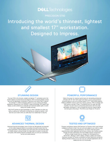
In addition, the dual-processor riser features six additional memory slots. The slots are numbered DIMM1 through DIMM6. DIMM1 isfurthest from the processor.Memory Population RulesYour computer requires DIMMs within a channel to be populated starting with the DIMMs farthest from the processor first. Thismeans the DIMM slots 1, 2 and 3 must be populated before DIMM slots 4, 5 and 6. In addition, when populating a Quad-rank DIMMwith a Single- or Dual-rank DIMM in the same channel, the Quad-rank DIMM must be populated farthest from the CPU.To maximize available memory bandwidth, DIM
Audio Stereo support integrated (5.1 channel support) NOTE: 5.1 channel support comes from an add-in card only PS/2 Two 6-pin mini-DIN connectors System board connectors: Three 7-pin SATA connectors Serial ATA SAS Four 7-pin SAS connectors Internal USB device Two 10-pin connector (supports two USB ports) Fans: Hard Disk Drive fan One 5-pin .