Transcription
4/25/2016Lesson 19 et438bET 438 b Digital Control and Data AcquisitionDepartment of TechnologyLESSON 19: PLC PROGRAMMINGTECHNIQUES1Lesson 19 et438bLEARNING OBJECTIVESAfter this presentation you will be able to: Identify the similarities and differences between ladder logic andladder programming of a PLC Convert ladder diagrams into PLC programs Use bit manipulating instructions to implement sequential logic control Use timer and counter instructions to implement more complex controlfunctions.21
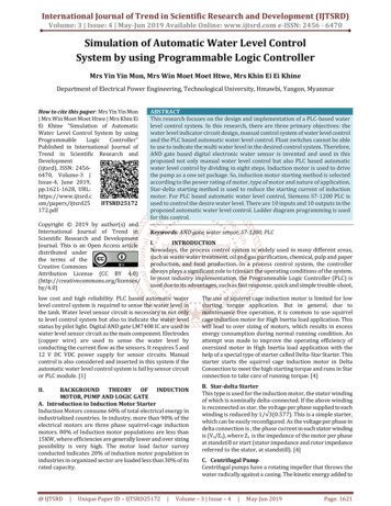
4/25/2016Lesson 19 et438bPLC LADDER LOGIC PROGRAMMINGBasic Concepts of PLC Ladder Logic ProgrammingInstructions look like schematicsymbolsSymbols attached to bit addressesin data mapsPLC ladder logic program based onlogical “continuity”All input symbols must test true forthe output symbol to be true3Lesson 19 et438bPLC LADDER LOGIC PROGRAMMINGExample systemBoolean Equation(1PB 2CR )((1PB 2CR ) 3LS) 4CR 5CR SOLACould program PLC in verbose language or use ladder logic symbols.Ladder logic used to reduce training of maintenance personnel42
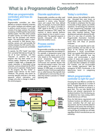
4/25/2016Lesson 19 et438bBASIC PLC PROGRAMMING INSTRUCTIONSBit or relay Instructions - test memory location bitsExamine if open: XIOexamines an input bit foran open conditionExamine if closed: XICexamines an input bitfor closed conditionBit addressBit addressLogic of XICLogic of XICInput Evaluation Rung EffectbitInput Evaluation Rung Effectbit1TRUEPass logicalcontinuity1FALSEBlock logicalcontinuity0FALSEBlock logicalcontinuity0TRUEPass logicalcontinuity5Lesson 19 et438bBASIC PLC PROGRAMMING INSTRUCTIONSOutput Instructions – Toggle output map bits when rung evaluatestrueOutput Energize (OTE)Instruction becomes true when all instructionsto rung become trueBit addressOutput latch and Output unlatchBit addressOutput latch become TRUE when input runginstructions become TRUE. Remains TRUE afterrung becomes FALSEOutput unlatch is used to reset the output latchinstructionBit address63
4/25/2016Lesson 19 et438bBASIC PLC PROGRAMMING INSTRUCTIONSMore Output InstructionsOne Shot InstructionInput that allows an event to occur only onceduring a program scan.OSRInstruction only responds to rising hardwareinput signalResponds to only FALSE to TRUE transitions7Lesson 19 et438bPROGRAMMING EXAMPLESRung Examples: What is the condition of the output instruction struction15141312 11 1098765432 10addr.0 I:0Input image tableshows a 0 bit, so XICevaluates to a FALSEI:3I:484
4/25/2016Lesson 19 et438bPROGRAMMING EXAMPLESRung example continued: What is the condition of the output instruction (T/F)?O:2I:0FalseFalse01746-IA8151413Rung is FALSE. soOTE is FALSE.This gives 0 inoutput image11746-OB1612 11 1098765432 10addr.O:00O:2O:49Lesson 19 et438bPROGRAMMING EXAMPLESRung Examples: What is the condition of the output instruction? (T/F)?O:3I:1XIOInstruction21746-IA841746-OB16Input image tableshows 0 bit in I:1/2XIO evaluatesTRUE.OTEInstruction0I:0I:1I:4Input image table105
4/25/2016Lesson 19 et438bPROGRAMMING EXAMPLESRung Examples: What is the condition of the output instruction? (T/F)?O:3I:1TrueTRUE21746-IA8Rung isTRUE, so OTE isTRUE.41746-OB16Output image tableO:21O:3O:511Lesson 19 et438bPROGRAMMING EXAMPLESRung Examples: What is the condition of the output instruction? 1746IA8O:131746-OB8OTEInstructionInput image tableLocation I:2/5 1. XICevaluates as TRUE.Location I:3/0 0.XIO instructionevaluates as TRUE.1I:20 I:3I:4126
4/25/2016Lesson 19 et438bPROGRAMMING EXAMPLESRung Examples: What is the condition of the output instruction? (T/F)?I:2I:3TRUETRUEO:1True51746-IA801746IA8Output image tableTRUE AND TRUE TRUEOutput image will have 1at address O:1/331746-OB81O:0O:1O:513Lesson 19 et438bPROGRAMMING EXAMPLESRung Examples: What is the condition of the output instruction? (T/F)?I:0O:0FALSE31746-IA8I:0True51746-OB8TRUE OR FALSE TRUEso rung is TRUE, OTE isTRUEOutput Image Table locationO:0/5 1. This output willbe energizedTRUE71746-IA8Input image table1The first XICinstruction at inputI:0/3 evaluates as aFALSE0XIC at input I:0/7evaluatesas TRUE (bit 1)I:0I:1I:4Input image tableshows I:0/0 1and I:0/3 0147
4/25/2016Lesson 19 et438bPROGRAMMING EXAMPLESRung Examples: What is the condition of the output instruction? (T/F)?FALSE OR FALSE FALSEThe rung evaluates FALSEO:4I:1FALSEFALSE01746-IA16The instruction OTE evaluates FALSE01746-OB16I:0FALSEIn the output image file, O:4/0 0 and output will not beenergized21746-IA16Input image table1At input I:1/0 0, XICevaluatesFALSEI:00 I:1At input I:0/2 1, XIOevaluates FALSE15Lesson 19 et438bTOGGLING BITS IN THE BIT FILEThe instructions XIC, XIO and OTE operate on bits in the B4 bit file also. Usethese bits like control relays in electromechanical schemes. Not related toI/O pointsRung ExamplesI:0FALSETRUEB3:2FALSETRUE21B3:2/2 bit number 2 in word 2 of the B3fileThis will be toggled by the input I:0/1I:0B3:1TRUEFALSE2FALSE1TRUE1FALSEB3:2/2 0I:0/1 1B3:2/2 1TRUEB3:1I:0/1 0Input at locationI:0/2 toggles the bitB3:1/1The XIC instruction actslike a seal-in contact inelectromechanicalsystems168
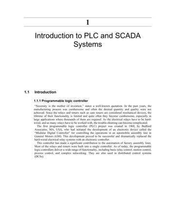
4/25/2016Lesson 19 et438bTIMER INSTRUCTIONSFALSEEnableBitTimerTypeTimer on-delay (TON)Done BitTRUEOperation: whenrung becomesTRUE, timeractivatesPresettimedelayTimer stops when rungbecomes FALSEAddressable BitsDONE (DN) - bit set (1) when ACC PREENABLE (EN) - bit set (1) when rung TRUETimer Timing (TT) - bit set (1) when ACC PREand rung TRUETime baseselectable insome modelsAccumulated time sinceactivation resets forRung FALSEACCUM ACC, accumulated timevalue since activationPRESET PRE, set time delay.depends on time base17Lesson 19 et438bTimer InstructionsTimer: off-delay (TOF)FALSETRUEOperationTimer activates whenrung conditions becomeFALSE (make a TRUE toFALSE transitionTimingTimer operated as long as rung remains FALSEAccumulator reset when rung goes TRUEPreset and Accumulator are the same as in TONAddressable bitsDONE (DN) - bit is reset (0) when ACC PREENABLE (EN) - bit is set (1) when rung conditions TRUETimer Timing (TT) - bit is set (1) when rung conditions FALSE and ACC PRE189
4/25/2016Lesson 19 et438bTIMER INSTRUCTION EXAMPLESTRUETimer T4:0 firsttimer in programI:0FALSETime base 0.01sec, preset to 100(1 sec) delay2Initial conditions I:0/2 0 Rung evaluates FALSEI:0/2 1 rung evaluatesTRUE t 0 sec1514ENTT1100Bit statusEN 0 TT 0 DN 0Bit status EN 1 TT 1 DN 0130DNINTERNAL USE ONLY0Preset Value (PRE)01Accumulated Value (ACC)When PRE ACC 100Bit statusEN 1 TT 0 DN 1EN 1 until I:0/2 0219Lesson 19 et438bOFF-DELAY TIMER EXAMPLETRUEInitial conditions: inputbit instruction XICB3:0/1 1 rung isTRUE . Timer is notactivatedB3:0FALSE1B3:0/1 0TRUE to FALSEtransition timerstarts1514ENTTDN01100Bit status EN 0 TT 1 ACC PREDN 1 ACC PRENote: DN remains set until ACC PRE130INTERNAL USE ONLYPreset Value (PRE)Accumulated Value (ACC)012When PRE ACC 100(1 sec)Bit status EN 0 TT 0ACC PRE DN 0If rung goes TRUE ACC 0EN 1 DN 1 TT 02010
4/25/2016TIMER EXAMPLELesson 19 et438bExample: Using a timer to turn on an output after a 3 second delayFALSETRUEI:101103When input changes stateFALSEO:0T4:02DNI:1/3 1 Rung is TRUE tTimer bit statusEN 1 TT 1 DN 00Initial conditions: Input address I:1/3 0Rung 1 evaluates FALSETimer Bit status EN 0 TT 0 DN 0 PRE 300Rung 2 T4:0/DN 0 XIC instruction evaluates FALSE so O:0/0 021Lesson 19 et438bTimer Example-ContinuedRung 2 T4:0/DN 0 rung FALSE O:0/0 0Output is de-energizedI:11103FALSET4:0TRUE21O:0OnDNAt t 3 secondsRung 1 I:1/3 1PRE ACC 300Timer bits EN 1 TT 0 DN 10Rung 2: T4:0/DN 1 XIC evaluates TRUERung is TRUE O:0/0 1 Output energized2211
4/25/2016Lesson 19 et438bCOUNTER INSTRUCTIONSCounters used to accumulate a count of events that cause FALSE to TRUEtransitions on the input to the counter rungCount Up (CTU) and Count Down (CTD)Count up instructionAddressable BitsCounter up enable (CU) bit is set (1) whenthe rung goes TRUECounter Done (DN) bit is set (1) when thepreset and accumulated values are equalCounter accumulator values are retentive.The value is not cleared until a RESinstruction is issued that addresses thecounter23Lesson 19 et438bCounter InstructionsCount Down (CTD)Counter decrements the preset value by 1 eachtime the rung makes FALSE-TRUE transitionWhen ACCUM PRESET the DN 1Underflow and Overflow conditionsBit OV set (1) when ACC 32,767 1BIt UV set (1) when ACC -32768-1Counter Done bit (CD) set (1) whenrung is TRUE Reset when the rung isFALSE2412
4/25/2016Lesson 19 et438bTHE RESET INSTRUCTIONReset (RES) - instruction used to reset timing and counting functionsReset - output instruction resets counters and retentive timers havingthe same address as the RES instruction Reset occurs when rungbecomes TRUEI:1Input I:1/6 actuatesRES instruction thatclears counter C5:0ACCUM 0 CU 04C5I:16025Lesson 19 et438bCOUNTER ADDRESSING EXAMPLEWhen I:1/5 1, rung 1 evaluatesTRUE CTU incrementsTRUEI:11C5:1/CU 1 when rung 1 TRUETurning on O:2/451746-IA8TRUEC5:1 11O:212CU4TRUEC5:1C5:1/DN bit will be set whenACC PRE 100 settingO:2/5 1O:213DNC5:15O:24OVThe overflow bit C5:1\OV 1 whenACC 32,767 1Counter “wraps around” 32,767 1 -32,76862613
4/25/2016Lesson 19 et438bPROGRAMMING LADDER LOGIC IN A PLCLadder Logic is similar to PLC rungs but not IdenticalLogical continuity not equivalent to electrical continuityProgramming ProcessMust divide system into field inputs, field outputs and internal (bit)devicesEvaluate the function of the field contacts when assigning XIOand XIC instructions to field inputs27Lesson 19 et438bProgramming Ladder Logic in a PLCExample: Three wire motor starter control with overload protectionrelayonM1 is motor contactor coil, contact M1 is auxiliary contact mechanicallylinked to M1Demonstrate operation2814
4/25/2016Lesson 19 et438bProgramming Ladder Logic in a PLCDefining Field DevicesField InputsField OutputStart/Stop, M1 contact and OL contacts are all field inputs for PLCoperation. Contacts located on external equipment.M1 coil is a field output. PLC must energize the motor contactor coil basedon the state of the inputs29Lesson 19 et438bProgramming Ladder Logic in a PLCStep 1 – Defining I/O and Developing External Wiring DiagramsDefine Address of I/O points and wire field devices to I/O points.Assume only slot 0 is populated with I/O points and all I/O 120 V acInputsOutput(s)STOP I:0/0 M1 START I:0/1 O:0/0OL I:0/2M1 I:0/3Contacts need a source of 120 V ac to actuate theelectronics of the I/O cards (120 V ac I/O)3015
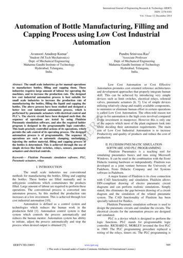
4/25/2016Lesson 19 et438bProgramming Ladder Logic in a PLCModule External WiringI:0/0O:0/0I:0/1I:0/2I:0/3Output wiringInput wiring31Lesson 19 et438bProgramming Ladder Logic in a PLCStep 2 – Converting Ladder Diagram into PLC ProgramHaving Field devices in the NC state does not automatically translate toXIC instruction (NC symbol)Rung instructions must evaluate to TRUE for OTE instruction to evaluateTRUE and energizing the external hardwareReview logic of bit instructionsLogic of XICLogic of XIOBit10Bit10ResultTRUEFALSEResultFALSETRUE3216
4/25/2016Lesson 19 et438bProgramming Ladder Logic in a PLCStep 2 – Converting Ladder Diagram into PLC ProgramO:0/0I:0/1I:0/0Programming rungexactly like ladderdiagram will not workI:0/2XIOXIOI:0/3M1 N.O.FalseOL N.C.Logic to implementSTART PBN.O.(START OR M1) AND STOP AND OL M1302 10110XIO evaluates asFALSE for STOP andOL contactsSTOP PBN.C.Input Image Map ( bit status)33Lesson 19 et438bProgramming Ladder Logic in a PLCCorrect Rung Programming: Motor Control ExampleInput Image Map ( bit status)StartM1 Aux10 1 0 13 2 1For rung to be TRUE input statement must evaluate TRUE(START OR M1) AND STOP AND OL M1O:0/0I:0/1I:0/0I:0/2I:0/30START STOP OL 1ORM1 STOP OL 1Use XIC forBoth OL and STOP34Use XIC instruction TRUE 1 FALSE 017
4/25/2016Lesson 19 et438bProgramming Ladder Logic in a PLCPLC rung for motor control: note all instructions are XICTRUETRUETRUESTOPI:0/0STARTOLI:0/1I:0/2M1XIC instructions allevaluate TRUE butM1O:0/0M1((TRUE OR FALSE) AND TRUE) AND TRUE M1TRUE M1 Output O:0/0 bit setI:0/3Pressing START gives the following input image0M13Start1112 1035Lesson 19 et438bProgramming Ladder Logic in a PLCRung Logic After the Release of STARTContact M1 changes state due to mechanical linkage to contactor coil so.TRUETRUESTOPI:0/0TRUESTART momentarycontact returns toopenSTARTOLM1I:0/1I:0/2O:0/0M1FALSEXIC instructions allevaluate TRUE butSTART inputI:0/3(START OR M1 ) AND STOP) AND OL M1(FALSE OR TRUE) AND TRUE AND TRUE M1TRUE M1 (contactor remains energized)START1M13102 1103618
4/25/2016Lesson 19 et438bProgramming Ladder Logic in a PLCRung Logic After the Pressing StopXIC at input I:0/0 evaluates as 2O:0/0M1I:0/3M1 Output and M1 Inputmechanically linked soM1 at I:0/3 evaluates FALSEFALSE(START OR M1 ) AND STOP) AND OL M1(FALSE OR TRUE) AND FALSE AND TRUE M1FALSE M1 (contactor is de-energized)1031012 1 0037Lesson 19 et438bET-438b Sequential Control and Data AcquisitionDepartment of TechnologyEND LESSON 19: PLC PROGRAMMINGTECHNIQUES3819
PLC ladder logic program based on logical "continuity" Symbols attached to bit addresses in data maps All input symbols must test true for the output symbol to be true 3 Lesson 19_et438b PLC LADDER LOGIC PROGRAMMING Boolean Equation Could program PLC in verbose language or use ladder logic symbols. Ladder logic used to reduce training of .