Transcription
METALLOGRAPHYLABORATORY MANUALEr. Tushar DaspattanaikLecturer in MetallurgyDIPLOMA(3rd YEAR-5th SEMESTER)Department of MetallurgicalEngineeringORISSA SCHOOL OF MINING ENGINEERING, KEONJHARA Government of Odisha institution with National Repute Established in theYear 1956 (Approved by AICTE, New Delhi & Affiliated to SCTE&VT,Odisha,BBSR)
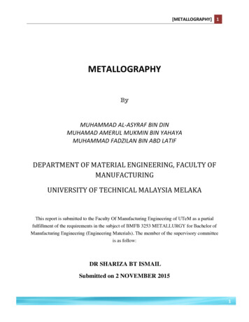
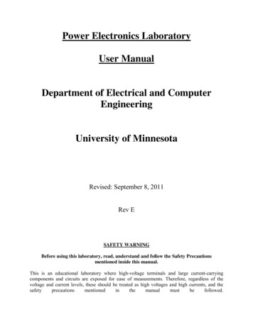
EXPERIMENT -1Aim: - To study the complete working operation of Metallurgical MicroscopeObjectives: 1. Familiarization with the different components of metallurgical components.2. Familiarization with compound optical microscope and metallographic.3. To study magnification system and how to increase in magnification.Introduction: The metallurgical microscope is the most important tool of the metallurgist. It consists anobjective and an eye-piece. Its primary function is to reveal the details of the object. Theclarity and the extent to which the details are revealed depends on the degree to whichthese optical systems are created.Principle: - A horizontal beam of light from the light source is reflected by means of aplane glass reflector downwards through the microscope objective on the surface of thespecimen some of these incident light reflected from the specimen surface will bemagnified and passing through the plane glass reflector and magnified again by upperlens system of the eye-piece.Constructional Details: - The table type microscopes are consisting of1. Stage: - A flat movable table supporting specimen. This can be moved up or down byknobs.2. Tubes: - The vertically movable tube containing eyepiece, objective and planereflector. The tube length varies from 160 mm to 250 mm.3. Rough & fine focus Adjustments - The limbs of microscope carry the coarse & fineadjustments.4. Objective – The body tube carries revolving nose piece carrying the three objectives.This enables quick change of the objective which helps for a quick resolving the structureof metal, the magnification of lenses is enlarged on focal length of the lens used
The important properties of an objective are1) Magnifying Power2) Resolving Power.It is the property by which an objective shows distinctly represented two small adjacentbonds in the structure of the object. This is usually expressed as number of lines per mmthat can be separated which depends on the numerical operator, the wavelength of thelight used. Resolution is particularly important during the microscopy of the microconstituents of metals consisting of fine lamination with core resolution which appears asone uniform area, where as an objective with higher numerical appearance reveals deepernature of the structure.Total magnification of microscope may be calculated asM L*E/ FWhere, L- The distance from back of objective to eyepiece.E- Magnification of Eye piece. & F- The focal length of objective.Eyepiece - It is named, as it is near to the eye. It is made up of various Powers such as5, 10, 15 etc.Uses: -The metallurgical microscope is useful in quality control department in Industriesto observe & study1) Differential phases 2) Porosity or defects.All these have a great effect on mechanical properties of material.List of Modern Microscopes –i) Watson Royal Microscope.ii) Van Lanes Hock Microscope.iii) Glass led Microscope.iv)Baker series Microscope.v) Leitr Microscope.
Conclusion: Proper selection of magnification is very much essential because –a. To travel inclusions in steel low magnification is used.b. To travel grain size, grain structure, twin boundaries etc. mediummagnification is used.c. To travel particular e.g. coarse perlite, fine martensite, bainite, etc. high magnificationis necessary.Therefore, proper study of metallurgical microscope is necessary.Fig- Metallurgical Microscope
EXPERIMENT-2Aim- Preparation of metallic specimen for metallographic study by grinding, polishingand etching.Objectives1. Familiarization with the procedure for preparation of material specimen formicroscopic examination.2. Familiarization with the compound optical microscopic and metallographic.3. Examination of surface characteristics of engineering materials.4. Grain size determination of metals.5. To study structural characteristics or constitution of metal or alloy in relation to itsphysical and mechanical properties.IntroductionThere are two examination methods1. Macroscopy2. MicroscopyIn macroscopy the examination of structural characteristic or chemical characteristic ofmetal or an alloy is done by unaided eye or with aid of low power microscope orbinocular usually under 10X.In microscopy similar examination is done with prepared metal specimens, employingmagnifications with optical microscope of from 100X to as high as 200X. Apart fromobservation of micro structural details in a metal or alloy, other defects such as grainboundaries, twins, precipitates can be observed readily in microscopic examination.The preparation of metallurgical specimen generally can e divided into series of stagessectioning/sampling, mounting, grinding, polishing & etching.
Procedure of Test1] Sectioning / SamplingThe choice of sample for microscopic study may be very important. If a failure is to beinvestigated the sampling should be chosen as close as possible to the area of the failure& should be compared with one taken from the normal section. If the material is soft,such as nonferrous metals or alloy & non heat treated steels, the section is obtained bymanual hack sawing /power saw. If the material is hard, the section may be obtained byuse of an abrasive cut off wheels. This wheel is thin disk of suitable cutting abrasiverotating at high speed. The specimen should be kept cool during the cutting operation.2] Rough Grinding –Whenever possible the specimen should be of a size & shape that is convenient to handle.A soft sample may be made flat by slowly moving it up to & back across the surface of aflat smooth file. The soft hard may be rough ground on a belt sander with specimen keptcool by frequent dipping in water during the grinding operation. In all grinding &polishing operation, the specimen should be moved perpendicular to the existingscratches this will facilitate, recognition of stage when the deeper scratches are replacedby shallower one characteristic of the finer abrasives. The rough grinding is continueduntil the surface is flat & free from wire brushes & all scratches due to hacksaw or cutoff wheel are no longer visible.3] Intermediate Polishing –After the previous processes the specimen is polishing on a series of emery papercontaining successively finer abrasive (Si-C). The first paper is usually no. 1 than 1/0,2/0, 3/0, & finally 4/0. The intermediate polishing operation using emery paper isusually done dry. However, in certain case such as preparation of soft material, SiliconCarbide has greater removal rate & as it is resin bonded, can be used with a lubricant,which prevents overshooting of the sample, minimizes shearing of soft metals & alsoprovides a rising action to flush away surface removal product so the paper won’t beclogged.
4] Fine polishing –The time consumed & the success of fine polishing depends largely on the case that weexercised during the previous polishing processes. The final approximation to the flat,scratch free surface is obtained by the use of a wet rotating wheel covered with a specialcloth that is charged by carefully sized abrasive particles. A wide range of abrasive isavailable for final polishing, while many will do a satisfying job, these appear to bepresence of gamma form of aluminium-oxides (Al2O3), for ferrous & copper basedmaterials & Cerium oxide for Aluminium, Magnesium & their alloys, other finalpolishing abrasives often used are diamond, chromium oxide & magnesium oxide etc. Achoice of proper polishing cloth depends upon the particular material being polished &the purpose of metallographic study. Many cloths are available of varying lap or pile,from those having no pile, such as silk, to those of intermediate pile such as broad cloth,billiard cloth, canvas cloth & finally to a deep pile such as velvet synthetic clothes arealso available for general purpose of which two under the trival names of gamal & microcloth are most widely used.5] Etching –The purpose of etching is to make the many structural characteristics of the metal or alloyvisible. The process should be such that the various parts of the microstructure may beclearly differentiated. This is to subject the polished surface to chemical action. In thealloys composed of two or more shapes. The competent are revealed during etching by apreferential attack of one or more of the constituents by the reagent because of differencein chemical composition of the phases. In uniform single phase alloy contact is obtainedand the grain boundaries are made visible because of difference in the rate at whichvarious grains are attacked by the reagent This difference in the rate of attack by reagentwhich is mainly associated with angle of the different grain structure section to the planeof the polished surface. Because of chemical attack of the chemical reagent the grainboundary appears as valleys in the polished surface light from the microscope hitting theside of these valleys will be reflected but of the microscope making the grain boundariesappears dark lines. The section of the appropriate etching reagent is determined by metalor alloys & the specific structure desired for viewing.
Etching ReagentCompositionUseNitric AcidWhite nitric acid ‘1 to 5 ml Carbon steels andethyl or methylcast ironalcohol’100 ml(95%Picric acidPicric acid ’49 ethylor methyl alcohol’Ferricchlorideand hydrochloricFerric chloride andStructure ofhydrochloric acid 50 ml austenitic nickelswater 100 mlstainless steelAmmonium hydroxideand hydrogenAmmonium hydroxide 90 Copper and its alloysparts water 5 partshydrogen peroxide 2 to 5Palmerton reagentChromic oxide 200Zinc and its alloysgm sodium sulphate 15 gmwaterCarbon steelsAmmonium molybdenum Molybdic acid 100 gmLead and its alloysammonium hydro 140mlwater 240 ml, filters add tonitric acid S.P.gr. 60 mlHydrofluoric acidHydrofluoric acid 0.5 mlAluminum and itsResult and Conclusion: Correct sample techniques if followed properly, will only reveal the microstructure of ametallic specimen. Otherwise it will be most difficult to distinguish between differentphase in the microstructure, the fine scratches on meta surface and grain boundaries etc.
EXPERIMENT-31.Aim-: Preparation and study of the Micro Structure of pure metals Mild Steel, LowCarbon steel and High Carbon Steel.2.Objectives:a.) To Learn the preparation of specimen for microscopic observation.b) To understand what Microscopy is, and how it can be used to observe Microstructureof metals.3. APPARATUS / EQUIPMENT3.1 Abrasive Cat-Off Wheel Machine 3 HP Motor, 1440 rpm Manual model 10” Diameter-wheel Fully enclosed Cutting Capacity 50mm Diameter & 75mm Height X 200mm Length.This Equipment is used to cut the sample pieces form the component of all kind ofmaterials.These sample pieces can be used microscopic observation.3.2 Specimen Mounting Press Manual Operation1” Mould CapacityDigital Temperature/ Time control unitPressure gauge for reading pressureAlarm indicator for cycle completion.
This Equipment is used to mount specimen in bakelite. Particularly is useful in hotmounting process.3.3 Belt Finishing Machine.This Equipment is used for rough Grinding of the Specimen 3.4 Polishing MachineMachine. Variable speeds 100rpm - 800rpm High torque PMDC motor with D. C. Drive. Water In and Drain Corrosion resistant fiber reinforced cover. 8” DiscThis Equipment is used to polish the specimen after rough grinding with the help ofpolishing clothe. It also useful for rough grinding with grinding disc.3.5 Metallurgical Microscope.Binocular model
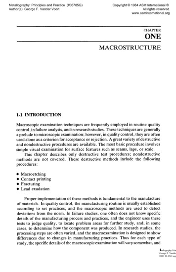
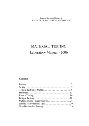
Eyepieces: 10X, 15X&20X Magnification: 10X-500X.This Microscope is used for microscopic observation of specimen with the adjustablemagnification.CONSUMABLES/ RAW MATERIAL -:Rod or Sample pieces of Pure Iron, Copper and Aluminium, Abrasive Polishing paper80grit/100 grit. Polishing powder4. THEORY -:Mild Steel, Low Carbon steel and High Carbon Steel are types of ferrous materials andare most important to the engineering application because of their wide range ofproperties and verity of applications. Theoretically, steels are the alloys of iron andcarbon in which the carbon content is between 0.008 to 2.0 per cent. The structures andproperties can be discussed with the help of Fe-C equilibrium diagram.4.1 Iron -Iron Carbide Equilibrium DiagramFig 5 Fe-Fe3C Phase Diagram
Figure 5 shows the equilibrium diagram for combinations of carbon in a solid solution ofiron. The diagram shows iron and carbons combined to form Fe-Fe3C at the 6.67%C endof the diagram. The left side of the diagram is pure iron combined with carbon, resultingin steel alloys. Three significant regions can be made relative to the steel portion of thediagram. They are theeutectoid E, the hypoeutectoid A, and the hypereutectoid B. The right side of the pureiron line is carbon in combination with various forms of iron called alpha iron (ferrite),gamma iron (austenite), and delta iron. The black dots mark clickable sections of thediagram.Allotropic changes take place when there is a change in crystal lattice structure. From2802 -2552 F the delta iron has a body-centered cubic lattice structure. At 2552 F, thelattice changes from a body-centered cubic to a face-centered cubic lattice type. At1400 F, the curve shows a plateau but this does not signify an allotropic change. It iscalled the Curie temperature, where the metal changes its magnetic properties. Two veryimportant phase changes take place at 0.83%C and at 4.3% C. At 0.83%C, thetransformation is eutectoid, called pearlite.gamma (austenite) — alpha Fe3C (cementite)At 4.3% C and 2066 F, the transformation is eutectic, called ledeburite.L(liquid) -- gamma (austenite) Fe3C (cementite)DefinitionsEutectoid: A eutectoid
METALLOGRAPHY LABORATORY MANUAL Er. Tushar Daspattanaik Lecturer in Metallurgy DIPLOMA (3rd YEAR-5th SEMESTER) Department of Metallurgical Engineering ORISSA SCHOOL OF MINING ENGINEERING, KEONJHAR A Government of Odisha institution with National Repute Established in the Year 1956 (Approved by AICTE, New Delhi & Affiliated to SCTE&VT, Odisha,BBSR)