Transcription
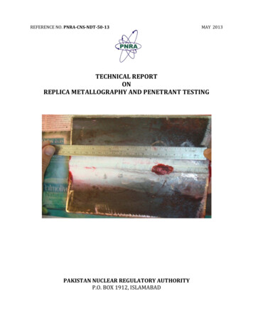
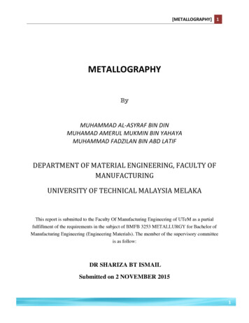
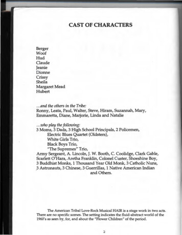
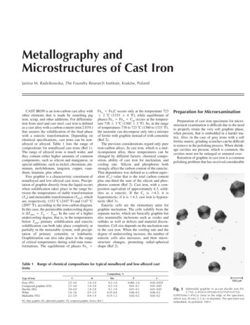
Metallography andMicrostructures of Cast IronJanina M. Radzikowska, The Foundry Research Institute, Kraków, PolandCAST IRON is an iron-carbon cast alloy withother elements that is made by remelting pigiron, scrap, and other additions. For differentiation from steel and cast steel, cast iron is definedas a cast alloy with a carbon content (min 2.03%)that ensures the solidification of the final phasewith a eutectic transformation. Depending onchemical specifications, cast irons can be nonalloyed or alloyed. Table 1 lists the range ofcompositions for nonalloyed cast irons (Ref 1).The range of alloyed irons is much wider, andthey contain either higher amounts of commoncomponents, such as silicon and manganese, orspecial additions, such as nickel, chromium, aluminum, molybdenum, tungsten, copper, vanadium, titanium, plus others.Free graphite is a characteristic constituent ofnonalloyed and low-alloyed cast irons. Precipitation of graphite directly from the liquid occurswhen solidification takes place in the range between the temperatures of stable transformation(Tst) and metastable transformation (Tmst), whichare, respectively, 1153 C (2107 F) and 1147 C(2097 F), according to the iron-carbon diagram.In this case, the permissible undercooling degreeis DTmax ⳱ Tst ⳮ Tmst. In the case of a higherundercooling degree, that is, in the temperaturesbelow Tmst, primary solidification and eutecticsolidification can both take place completely orpartially in the metastable system, with precipitation of primary cementite or ledeburite.Graphitization can also take place in the rangeof critical temperatures during solid-state transformations. The equilibrium of phases Fec ⳱Fe Ⳮ Fe3C occurs only at the temperature 723Ⳳ 2 C (1333 Ⳳ 4 F), while equilibrium ofphases Fec ⳱ Fe Ⳮ Cgr occurs at the temperature 738 Ⳳ 3 C (1360 Ⳳ 5 F). So, in the rangeof temperatures 738 to 723 C (1360 to 1333 F),the austenite can decompose only into a mixtureof ferrite with graphite instead of with cementite(Ref 2).The previous considerations regard only pureiron-carbon alloys. In cast iron, which is a multicomponent alloy, these temperatures can bechanged by different factors: chemical composition, ability of cast iron for nucleation, andcooling rate. Silicon and phosphorus bothstrongly affect the carbon content of the eutectic.That dependence was defined as a carbon equivalent (Ce) value that is the total carbon contentplus one-third the sum of the silicon and phosphorus content (Ref 2). Cast iron, with a composition equivalent of approximately 4.3, solidifies as a eutectic. If the Ce is 4.3, it ishypereutectic; if it is 4.3, cast iron is hypoeutectic (Ref 3).Eutectic cells are the elementary units forgraphite nucleation. The cells solidify from theseparate nuclei, which are basically graphite butalso nonmetallic inclusions such as oxides andsulfides as well as defects and material discontinuities. Cell size depends on the nucleation ratein the cast iron. When the cooling rate and thedegree of undercooling increase, the number ofeutectic cells also increases, and their microstructure changes, promoting radial-sphericalshape (Ref 2).Preparation for MicroexaminationPreparation of cast iron specimens for microstructural examination is difficult due to the needto properly retain the very soft graphite phase,when present, that is embedded in a harder matrix. Also, in the case of gray irons with a softferritic matrix, grinding scratches can be difficultto remove in the polishing process. When shrinkage cavities are present, which is common, thecavities must not be enlarged or smeared over.Retention of graphite in cast iron is a commonpolishing problem that has received considerableTable 1 Range of chemical compositions for typical nonalloyed and low-alloyed castironsComposition, %Type of ironGray (FG)Compacted graphite (CG)Ductile (SG)WhiteMalleable 0.2FG, flake graphite; SG, spheroidal graphite; TG, tempered graphite. Source: Ref 1Fig. 1Spheroidal graphite in as-cast ductile iron %Cu) close to the edge of the specimen,which was 30 mm (1.2 in.) in diameter. The specimen wasembedded. As-polished. 100⳯
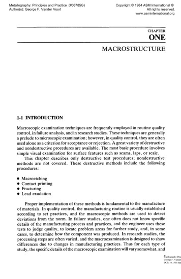
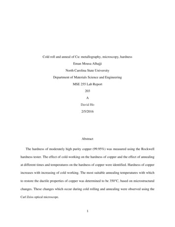
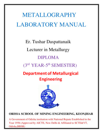
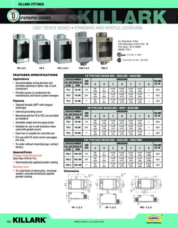
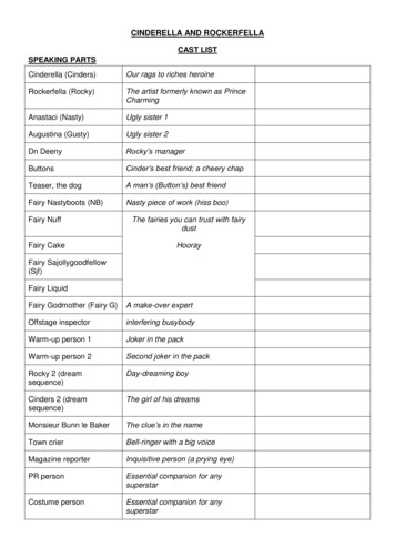
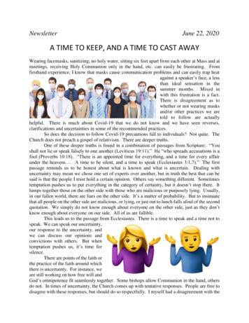
566 / Metallography and Microstructures of Ferrous Alloysattention. Coarse grinding is a critical stage, so,if the soft graphite is lost during coarse grinding,it cannot be recovered in subsequent steps andFig. 2Same as-cast ductile iron as in Fig. 1, but thespecimen was not embedded. The arrows showthe pulled-out graphite. As-polished. 100⳯will be seen as an open or collapsed cavity. Silicon carbide (SiC) grinding papers are preferredto emery, because SiC cuts efficiently, while emery paper does not, and SiC produces less dam-Fig. 4Same as in Fig. 3 but close to the center of thespecimen. As-polished. 100⳯age. Fresh paper should always be used; nevergrind with worn paper. White iron, by contrast,contains extremely hard iron carbides that resistabrasion and tend to remain in relief above thesofter matrix after polishing (Ref 4).Quality-control studies, based on image analysis measurements of the amount of phases andthe graphite shape and size, also need perfectlyprepared specimens with fully retained graphitephase and with microstructural constituents correctly revealed by etching.Specimen Preparation. The metallographicspecimen preparation process for microstructuralinvestigations of cast iron specimens usuallyconsists of five stages: sampling, cold or hotmounting, grinding, polishing, and etching witha suitable etchant to reveal the microstructure.Each stage presents particular problems in thecase of cast iron. Of course, the graphite phaseis studied after polishing and before etching.Sampling is the first step—selecting the testlocation or locations to be evaluated metallographically. Usually, cast iron castings have aconsiderable variation in microstructure betweensurface and core. Selection of the test location isvery important to obtain representative resultsfrom the microstructural examination. Samplescan be obtained by cutting them out from eithera large or small casting or from standard testbars, such as microslugs, ears, or keel bars; however, the microstructure of these pieces may notbe representative for the actual casting due tosubstantial differences in the solidification rates.Production saws, such as large, abrasive cutoffsaws, band saws, or power hacksaws, can beused for dividing medium-sized casting intosmaller samples. In the case of very large castings, flame cutting may be used. Next, the piecesFig. 5Fig. 3Flake graphite in as-cast gray iron %Cu) close to the edge of the unembedded specimen,which was 30 mm (1.2 in.) in diameter. As-polished. 100⳯Temper graphite in malleable iron u-0.09%Cr-0.003%Bi) after grinding on P1000 SiCwaterproof paper. The casting was annealed at 950 C(1740 F), held 10 h, furnace cooled to 720 C (1330 F),held 16 h, and air cooled. The arrows show the pulled-outgraphite. As-polished. 400⳯Same as in Fig. 5 but after polishing with 9 lmdiamond suspension. The arrows show thepulled-out graphite. As-polished. 400⳯Fig. 6
Metallography and Microstructures of Cast Iron / 567can be reduced to the desired size for metallographic specimens by using a laboratory abrasive cutoff saw or a band saw. If the casting wasFig. 7Same as in Fig. 6 but after final polishing withthe 1 lm diamond paste applied on a naplesscloth. Graphite is free of any visible pullouts. As-polished.400⳯Fig. 8Same as in Fig. 7 but after final polishing withthe 1 lm diamond suspension applied on anapped cloth. The arrows show the pulled-out graphite. Aspolished. 400⳯sectioned by flame cutting, the specimen mustbe removed well away from the heat-affectedzone. The pieces cut out for metallographic examination may be ground prior to mounting (thismay be done to round off sharp cut edges or toreduce the roughness of band-saw-cut surfaces)and subsequent preparation. Overheating isavoided by proper selection of the speed of cutoff saws, the use of the correct wheel, and adequate water cooling. Overheating during grinding is avoided by using fresh abrasive paper andproper cooling. When metallographic specimensare cut out from the standard cast bars, they aresometimes prepared using standard machineshop equipment, such as turning in a lathe ormilling. These devices can deform the testpiecesurfaces to a considerable depth, so care must beexercised to remove any damage from theseoperations before starting specimen preparation.Mounting. Specimens can be mounted in apolymeric material using either cold or hotmounting procedures. The mounting resin ischosen depending on the cast iron hardness (softor hard) and the need to enhance edge retention.Use of an incorrect resin, or ignoring the mounting process, can make it very difficult to obtainproperly polished graphite in the area close tothe specimen edge. Figures 1 and 2 show themicrostructure of spheroidal graphite in ductileiron close to the edge of the specimens, whichwere cut off from a 30 mm (1.2 in.) diameter barand polished with and without embedding in apolymer resin, respectively. In the specimen prepared without embedding in a resin, the graphitewas pulled out, while in the specimen that wasembedded in a resin and prepared, the graphitenodules were perfectly retained. Figures 3 and 4show that the uniform grinding of nonmountedspecimens is more difficult, and the flake graphite in gray iron close to the edge of such a specimen is not polished perfectly, in comparison towell-polished graphite in the mounted specimen.Grinding and Polishing. To ensure propergraphite retention, the use of an automatedgrinding-polishing machine is recommendedover manual preparation. The automated equipment makes it possible, in comparison to manualspecimen preparation, to properly control theorientation of the specimen surface relative tothe grinding or polishing surface, to maintainconstantly the desired load on the specimens, touniformly rotate the specimens relative to thework surface, and to control the time for eachpreparation step. Proper control of these factorsinfluences graphite retention, although other factors are also important.A good, general principle is to minimize thenumber of grinding and polishing stages. Also,the load on each specimen, or on all specimensin the holder, must be chosen to obtain a correctly polished surface in the shortest possibletime. This precludes the risk of pulling out thegraphite phase and ensures that the graphite precipitates will be perfectly flat with sharp boundaries.The recommended procedure for automatedpreparation of the specimens of nonalloyed andlow-alloyed cast iron with graphite specimens isto grind with a high-quality, waterproof 220- or240-grit (or equivalent) SiC paper until plane,with a load of 100 N for six specimens mountedin the sample holder, with central loading. Pol-Fig. 9Fig. 10White high-chromium iron (Fe-3.2%C-4.65%Cr2.9%Mn-0.51%Si-0.050%P-0.024%S). Eutecticand secondary carbides in the matrix. Specimen was prepared correctly. The casting was austenitized at 1000 C(1830 F), held 1 h, furnace cooled to 400 C (750 F) for2 h, taken to salt bath at 400 C (750 F), held for 4 h, andair cooled. Etched with glyceregia. 500⳯White high-chromium iron (Fe-3.16%C8.86%Cr-0.50%Si-3.04%Mn-0.051%P0.018%S). Eutectic and secondary carbides in the matrix.Specimen was prepared incorrectly. The casting was austenitized at 1000 C (1830 F), held 1 h, furnace cooled to700 C (1290 F) for 2 h, taken to salt bath at 700 C (1290 F), held 4 h, and air cooled. Etched with glyceregia. 500⳯
568 / Metallography and Microstructures of Ferrous Alloysishing is carried out in four steps with a differentgrain size diamond paste:Step1234Diamond pastegrain size, lm931(b)Load,NRecommendedpolishing clothDuration120(a) 5 min(d)120(a) 3 min(d)120(a) 2 min(d)25(c) 45–60 s(e)Napless wovenNapless wovenNapless wovenNapless syntheticpolyurethane(a) Load per six specimens. (b) Aqueous 0.05 lm alumina suspension.(c) Load per single specimen (switching to individual force to makespecimen cleaning easier). (d) Comp direction. (e) ContraFigure 5 shows temper graphite in malleableiron after the last step of grinding, which wascarried out in three steps using, consecutively,SiC grit papers P220, P500, and P1000. Figure6 shows the same specimen after grinding onP220 SiC paper and then polishing with 9 lmdiamond paste according to the procedure givenpreviously. In both cases, there is some pulledout graphite after these steps. Each specimen wasprepared further. The specimen ground withthree SiC steps was polished with 3 lm diamondsuspension on a napless cloth and then with 1lm diamond suspension on a napped cloth. Thepulled-out graphite was still visible. However,the specimen ground with P220 SiC and polished with 9 lm diamond paste, when finishedwith the recommended practice given previously, was free of any visible pullouts, as shownin Fig. 7. By using a napped cloth and an aqueous 1 lm diamond suspension for the final diamond polishing step, it was impossible to obtainperfectly retained graphite, as shown in Fig. 8.Napped cloths should not be used with diamondabrasive, either in paste, suspension, or aerosolform. Graphite retention appears to be slightlybetter using diamond paste and the preferred lubricant than with an aqueous suspension, although more work needs to be conducted to determine if this difference is important. Finalpolishing with an alumina suspension, such asMasterprep alumina (Buehler, Ltd.), makes thegraphite boundaries sharper by removing thematrix, which was smeared over the edge of thegraphite during grinding and was not removedby the diamond polishing steps.Alloyed ch
Metallography and Microstructures of Cast Iron / 567 can be reduced to the desired size for metallo-graphic specimens by using a laboratory abra-sive cutoff saw or a band saw. If the casting was sectioned by flame cutting, the specimen must be removed well away from the heat-affected zone. The pieces cut out for metallographic ex- amination may be ground prior to mounting (this may be done to .