Transcription
LABORATORYQUALITYMANUALFor
QUALITY MANUAL FOR()TABLE OF CONTENTSTitleSectionPageOrganization and Organizational PoliciesLaboratory Technical StaffLaboratory EquipmentTest Records and Reports
ORGANIZATION AND ORGANIZATIONAL POLICIESThis section of the QM contains the following information:1. The legal name and address of the laboratory.2. The legal name and address (if different from item [1]) of the main office orowner company.3. Any additional information to identify the organization with responsibility for thelaboratory.4. The ownership and management structure of the laboratory.5. The organization chart of the laboratory, clearly showing relevant internalorganizational components.
This form revised:by:Legal Name and Address:Main Office Address:Ownership:Owner Office Address:(if different from above)Ownership/Management Structure:Title/PositionChief Executive Officer(or how Organizational Chart on following page)NameOther Affiliation
LABORATORY / TECHNICAL STAFFThis section of the QM contains the following information:1. Position description(s) for each technical operational position shown on theorganizational chart.2. A brief biographical sketch of the person currently employed for each technicaloperational position shown on the organizational chart.3. A description of the method(s) used to ensure all personnel are trained to performtests conducted by this laboratory in accordance with standard procedures.4. A description of the method(s) used to evaluate the competency of each staffmember to perform tests conducted by this laboratory, to ensure all testing isperformed in accordance with standard procedures.5. A form summarizing and recording training and evaluation activities undertaken tocomply with the procedures described in items (3) and (4).
This form revised:by:POSITION:JOB DESCRIPTION:SUPERVISION EXERCISED / tions:Experience:
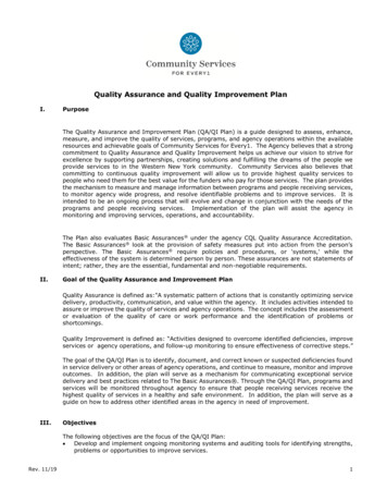
This form revised:by:TECHNICIAN TRAININGCenter for Training Transportation ProfessionalsCTTP - TECHNICIAN TRAINING RECORDNameTrainingCert. No.BasicAggregateSoilsInsert copies of training certificates for above training following this page.ACHMPCC
TECHNICIAN QUALIFICATION PROGRAMThe Arkansas State Highway and Transportation Department (Department) has contracted with theUniversity of Arkansas to conduct training for qualification of technicians at the Center for TrainingTransportation Professionals (CTTP).Qualification of technicians is in four areas of materials testing: 1) Basic Aggregates; 2) Soils/Aggregate;3) Hot Mix Asphalt; and 4) Portland Cement Concrete Testing. Before a technician may become qualifiedin Soils/Aggregate, Hot Mix Asphalt, and Portland Cement Concrete, the technician must first becomequalified in Basic Aggregates. The Center address is:Center for Training Transportation ProfessionalsUniversity of Arkansas at Fayetteville4190 Bell Engineering CenterFayetteville, Arkansas 72701(479) 575-3997Fax (479) 575-7639Qualification includes a demonstration of proficiency by the technician and a written test covering thearea of qualification. Upon acceptable completion of this program, the technician will be issued astatement of qualification showing the technician’s area of qualification. Technicians must recertify everyfour years for Soils and Hot mix asphalt. Concrete recertification is required every five years.The areas of qualification and the items included in each area are as follows:1) Basic AggregatesSampling by Random NumberSampling of AggregatesReducing Field Samples SizeMoisture ContentDeleterious MaterialsCrushed ParticlesParticle Size Determination (Gradation)Materials Finer Than #200 by WashingFine Aggregate Specific GravityCoarse Aggregate Specific Gravity2) Soils/AggregateSampling SoilsDry Soil PreparationWet Soil PreparationMoisture Content of SoilsMoisture Using Calcium Carbide TesterParticle Size Determination (Gradation)Atterburg LimitsProctors & Coarse Particle CorrectionIn-place Density & Moisture DeterminationNuclear MethodsAHTD 465AASHTO TAASHTO TAASHTO TAHTD 302AHTD 304AASHTO TAASHTO TAASHTO TAASHTO T2, AHTD 35248, AHTD 349255, AHTD 34827, AHTD 305118485AHTD 30AASHTO T 87, AHTD 35AASHTO T 146AASHTO T 265, AHTD 348AASHTO T 217, AHTD 347AASHTO T 88, AHTD 352AASHTO T 89 & T 90AHTD 353 & 354AASHTO T 99, T 224,T 180, & T 272AHTD 350, 356, 344, & 355AASHTO T 310, AHTD 330
3) Asphalt Plant and Field TestingSampling by Random NumberSampling Bituminous Paving MixturesAC Content Determination by Nuclear GaugeRice Theoretical Specific GravityBulk Specific GravityNuclear Density DeterminationVolumetric MethodPercent Air Voids in Paving MixturesDensity Using Gyratory CompactorAsphalt Content by Nuclear MethodResistance To Moisture DamageMixture Conditioning of HMAVolumetric Design for HMAAHTD 465AASHTO T 168, ASTM D979AASHTO T 287AASHTO T 209AASHTO T 166ASTM D 2950, AHTD 461AASHTO MP 2AASHTO T 269AASHTO T 312AHTD 449 & 449AAASHTO T 283AASHTO PP 2AASHTO PP 284) Portland Cement Concrete TestingSampling Freshly Mixed ConcreteMaking and Curing of CylinderSlump of Hydraulic Cement ConcreteAir ContentUnit Weight of Freshly Mixed 9152121
PERIODIC TECHNICIAN COMPETENCY REVIEWAll materials technicians shall be trained prior to performing test procedures.following training procedure shall be followed for each test:The1. The trainee shall have access to the latest copy of the applicable test specification.2. A qualified technician shall demonstrate the test procedure.3. The laboratory supervisor shall observe the trainee and document his/her ability toperform the test procedure.4. Technician performance shall be reviewed at 6-month intervals.5. The supervisor shall record the test demonstrated, the date of review, andperformance results.6. If an unsatisfactory result is recorded for a test method, the supervisor shall reviewthe test method and repeat the evaluation.(See table on following page)
This form revised:by:TECHNICIAN TRAINING AND EVALUATION RECORDTECHNICIANTEST METHODDATEEVALUATORRESULTS (P/F)
LABORATORY EQUIPMENTThis section of the Quality Manual contains the following information:1. An inventory of major sampling, testing, calibration, and verification equipmentassociated with the test methods employed by the testing laboratory.2. A copy of the manufacturer’s instructions pertaining to the test equipment listedin item (1), if available, or a reference to the location of such documents.3. A description of procedures used regarding all calibration and verification ofequipment.4. In-house procedures used for calibration and verification of equipment.5. A description of equipment used in performing tests that requires calibration orverification. Included with the description is all pertinent information regardingthe calibration/verification items, calibration/verification procedures and intervals,and equipment used in such procedures. Calibration worksheets/recordspertaining to each item of equipment follow the equipment description page.(See table on following page).
General Laboratory EquipmentItem ration/VerificationIntervalCalibrationProcedure
Asphalt Laboratory EquipmentItem ration/VerificationIntervalCalibrationProcedure
Soils Laboratory EquipmentItem ration/VerificationIntervalCalibrationProcedure
Concrete Laboratory EquipmentItem ration/VerificationIntervalCalibrationProcedure
Equipment Calibration/Verification Record(Required for each item on laboratory equipment listing)Item Description:Manufacturer:Inventory/Serial Number:Calibration/Verification Interval:Calibration Procedure:DateCalibration/Verification ItemChecked by:Comments
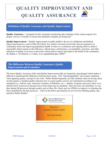
IN-HOUSE PROCEDURE #PROCEDURE FOR VERIFYING SIEVESItem: SievesPurpose:This method provides instructions for checking the physical condition of laboratory test sievesranging in size from 75 mm (3 in.) to 0.075 mm (No. 200).Inspection Equipment Required:1. A caliper readable to 0.01 mm (Use for No. 4 sieve and coarser.)Tolerance:Sieves shall meet the physical requirements specified in AASHTO M 92.Procedure:(Step 1 applies only to sieves having openings greater than or equal to 4.75 mm)1. Select approximately 30 openings (or all square openings if less than 30), in segmentsof 3 or 4 openings along a 45-degree line. Measure and record both dimensions of eachsieve opening.2. Inspect the general condition of the sieve. Check the frame and solder joints for cracksor holes (check for pin holes in the finer sieves).3. Make sure the sieve has an appropriate label.4. Check for tightness of the wires on each individual sieve.
Sieve Calibration WorksheetEquipment ID:Manufacturer:Model #:Serial #:Location:Calibration Item:Date:Performed by:Next Calibration Due:Last Calibration:Verify physical condition of sieve and critical dimensions forsieves larger than #4 (4.75 mm)Calibration Procedure:In-House Procedure #Calibration Equipment:Digital CalipersComment 112131415161718192021222324252627282930Requirement (according to AASHTO M 92) Comments:Initial By:
WIRE CLOTH SIEVE INSPECTION REPORTDate: Verified by:Sieve Sizesmm (Millimeters)Minimum MaximumCondition75 mm (3”)72.877.2GoodReplace62.5 mm (2 1/2 ")61.164.9GoodReplace50 mm (2”)48.551.5GoodReplace37.5mm (1 1/2 ")36.438.6GoodReplace31.3mm(1 1/4 ")30.532.6GoodReplaceGoodReplace28 mm (1 1/8 “)25mm (1”)24.225.8GoodReplace19 mm (3/4 ")18.419.6GoodReplace5/8 "15.S16.5GoodReplace12.5 mm (1 2 “)12.1112.89GoodReplace9.5 mm(3/8 ")9.29.8GoodReplace4.75 mm (# 4)4.64.9GoodReplace#8GoodReplace#10GoodReplace# 16GoodReplace# 20GoodReplace# 30GoodReplace# 40GoodReplace# 50GoodReplace# 80GoodReplace# 100GoodReplace# 200GoodReplaceDust ReceiverGoodReplaceQuantityThe table is for sieve openings in mm (millimeters). On the identification plate of some sievesthe sieve opening will be in microns. To convert microns to mm (millimeters): multiply the number ofmicrons by 0.001.Example: On the identification plate of a #16 sieve - the openings indicated are 1190 microns.(1190 x 0.001) 1.19 mmA #16 sieve Minimum allowable opening 1.135 mmMaximum allowable opening 1.225 mm
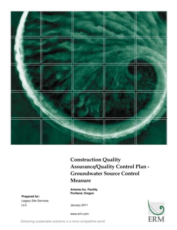
IN-HOUSE PROCEDURE #PROCEDURE FOR CALIBRATION OFSCALES OR BALANCES(AASHTO M 231)Purpose:This procedure provides instructions for checking the accuracy of scales and balances.Inspection Equipment1. Standard Weight Set of sufficient mass to reach 90% of scales capacity.2. A level is required to check the scale's level position, if one is not built into the unit.Procedure:1. Turn electronic scales on allowing for a warm up of approximately 30 minutes.2. Ensure that the scale base is seated on all comers and is level. (NOTE: Some leveling devicesare located under the scale pan.3. Be aware of excessive air movement during the calibration process. Document if airmovement appears to be excessive.4. Check for Off-Center Error. Measure this effect by placing the load (90 % of capacity) atvarious positions on the pan and observe any differences in indication. The difference betweenthe lowest and the highest indication is the maximum Off-Center Error, which should be withinthe accuracy range listed for the class of scale being checked.5. Set the zero point and the full-scale indication. Place weights on the pan in increasingincrements as indicated on calibration form. Observe and record the indications. The differenceat any point is the inaccuracy.
SCALE OR BALANCE VERIFICATIONMANUFACTURER: MODEL#:INVENTORY#: CLASS OF SCALE:MAXIMUM CAPACITY: SMALLEST DIVISION:Off-Center Error: Center-Front: Right: Center:Center-Back: Left:GRAMSSCALE READINGVERIFIES0.5(.0011 1b.)YesNo1(.0022 1b.)YesNo2(.0044 1b.)YesNo3(.0066 1b.)YesNo5(.011 1b.)YesNo10(.022 1b.)YesNo20(.044 1b.)YesNo30(.066 1b.)YesNo50(.110 1b.)YesNo100(.220 1b.)YesNo200(.440 1b.)YesNo300(.660 1b.)YesNo500(1.102 1b.)YesNo1000(2.205 1b.)YesNo2000(4.409 1b.)YesNo5000(11.02 1b.)YesNo10000(22.05 1b.)YesNo15000(33.07 1b.)YesNo20000(44.09 1b.)YesNoVERIFIED BY:DATE:NOTE CHECK OFF-CENTER ERRORS OF ELECTRONIC SCALES BY PLACING WEIGHT THAT ISAPPROMMATELY 90% OF SCALE CAPACITY NEAR THE CENTER AND AT EACH CORNER.
SCALE OR BALANCE CALIBRATIONGENERAL PURPOSE BALANCES AND SCALESCLASS PRINCIPAL SAMPLE WEIGHT READABILITY ACCURACYG22 kg or less0.1gG5Over 2 kg thru 5 kg1gG20Over 5 kg thru 20 kg5gG100Over 20 kg20gACCEPTANCE TOLERANCES FOR DIFFERENT CLASSES OF SCALESCLASS G2TEST WEIGHTTOLERANCE T WEIGHT1.1-0.92.1-1.93.1-2.95.1-4.910 .1- 8300.3-299. 7500.5-499.61001.0-999.02002.0-1998.0CLASS G20TOLERANCE RANGE0.1 g or 0.1 %1g or 0.1%5g or 0.1%20g or 0.1 %CLASS G5TEST WEIGHT2TOLERANCE RANGE3. 0-1 8.05005.0-4995.0TEST WEIGHTCLASS 05.0-495.020002020.0-1980.010001005. 0-995.050005020. 005.0-4995. 01500015020.0-14980 -14985.02000020020.0-19980.0
IN-HOUSE PROCEDURE #PROCEDURE FOR VERIFYING OVENSItem: OvenPurpose:This method provides instructions for verifying the settings on general-purpose ovens.Inspection Equipment Required:1. A calibrated thermometer graduated in 1.0 C increments h
Sampling of Aggregates AASHTO T 2, AHTD 35 Reducing Field Samples Size AASHTO T 248, AHTD 349 Moisture Content AASHTO T 255, AHTD 348 Deleterious Materials AHTD 302 Crushed Particles AHTD 304 Particle Size Determination (Gradation) AASHTO T 27, AHTD 305 Materials Finer Than #200 by Washing AASHTO T 11 Fine Aggregate Specific Gravity AASHTO T 84 Coarse Aggregate Specific Gravity AASHTO T 85 2 .