Transcription
REFERENCE NO. PNRA-CNS-NDT-50-13MAY 2013TECHNICAL REPORTONREPLICA METALLOGRAPHY AND PENETRANT TESTINGPAKISTAN NUCLEAR REGULATORY AUTHORITYP.O. BOX 1912, ISLAMABADi
Intentionally Left Blanki
Intentionally Left Blankiii
Contents1.INTRODUCTION . 12.REPLICA METALLOGRAPHY . 12.1A.B.C.3.LIQUID PENETRANT TESTING (PT) . 43.13.24.GENERAL STEPS FOLLOWED IN REPLICA METALLOGRAPHY .2SURFACE PREPARATION .2PREPARATION OF REPLICA .2MICROSTRUCTURAL ANALYSIS AND INTERPRETATION OF RESULTS .3BASIC STEPS PT .4ADVANTAGES AND DISADVANTAGES OF PENETRANT TESTING .7CONCLUSION . 8iv
List of FiguresFigure 1: Portable Grinder/PolisherFigure 2: Transcopy Replica KitFigure 3: Micrographs; Specimen (Left) and Prepared Replica (Right)Figure 4: Application of penetrant after surface preparationFigure 5: Indication development after application of developerFigure 6: Inspection of indication and position measurementv234567
1.INTRODUCTIONNondestructive testing (NDT) consists of test methods used to examine an object, material or systemwithout impairing its future usefulness. A limited scale NDT laboratory has been established in PNRA fortraining purpose of nuclear inspectors and to enhance the quality of regulatory oversight of nuclear powerplants in Pakistan. The following equipments are available in the laboratory:1.2.3.4.5.6.7.8.Ultrasonic flaw detectorUltrasonic thickness gaugePortable hardness testerEddy current test equipmentCoating thickness gaugePenetrant testingUniversal hardness testerReplica Metallographic EquipmentA PNRA task force comprising officers of CNS and SNRS was established to make the equipmentfunctional. This report is submitted after completion of self training on the Replica MetallographicEquipment and Penetrant Technique. The following team was engaged in this activity:1.2.3.4.Muhammad RafiqAliullah JanMansoor ArshadZafar Abbas(SE, CNS)(SE, CNS)(AE, CNS)(AE, SNRS)The training program comprised of the following activities:1. Study of Equipment Manual of Replica Metallography2. Study of PT Techniques3. Practical Work2. REPLICA METALLOGRAPHYSurface Replication is a well developed electron microscopy sample preparation technique thatcan be used to conduct in situ measurements of the microstructure of components. The in situdetermination of microstructural deterioration and damage of materials subjected to variousenvironments is an objective of any nondestructive evaluation (NDE) of structural components.The need to assess the condition of power plant and petrochemical metallic components on alarge scale recently led to the application of surface replication to the problem of determiningremaining life. The usual method of metallographic investigation which may involve cuttinglarge pieces from the component so, that laboratory preparation and examination can beperformed, usually renders the component unfit for service or necessitates a costly repair. As aresult, metallographic investigations are avoided, and important microstructural information isnot available for evaluating the component for satisfactory performance. Therefore, an in situ orfield microscopy examination is needed to aid in the proper determination of component life.1
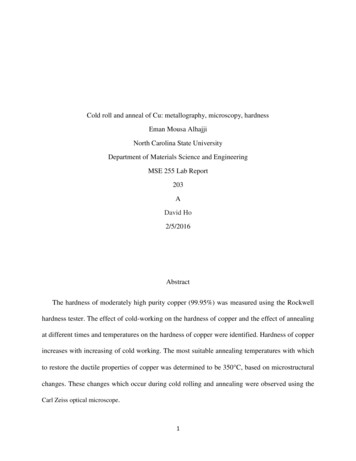
This technique gives the flexibility of observing microstructures in the comfort of a lab instead of harshplant conditions (heat, radiation etc.).2.1 General Steps Followed In Replica MetallographyIn Replica Metallography steps followed are similar to that of common methods used inlaboratory metallography with the exception that the part to be viewed is not required to bebrought to the laboratory2.2 Surface PreparationSurface preparation holds key in revealing the microstructure to be studied. It involves steps likegrinding, polishing and etching. Components in service usually have a well-developed corrosionor oxidation product or a decarburized layer on the surface that must be removed beforereplication. In Situ, Replication Metallography utilizes portable grinding and polishing unit toserve this purpose. Grinder/Polisher unit is shown in figure 1.Figure 1: Portable Grinder/PolisherNote: During work at NDT Lab SNRS these steps were omitted because the equipment was not inworking condition. Instead already prepared specimens were used for preparation of replicas.2.3 Preparation of ReplicaReplication of a surface can involve either direct or indirect methods. In the direct, or singlestage, method, a replica is made of the specimen surface and subsequently examined in themicroscope, while in the indirect method; the final replica is taken from an earlier primaryreplica of the specimen surface. Only the direct method will be considered in this effort becauseit lends itself more favorably to on-site preparation.Replication of surface was performed by using Transcopy Replica-Kit. Replica of the samplewas prepared as:i.Two drops of replication fluid were applied to the replica foil.2
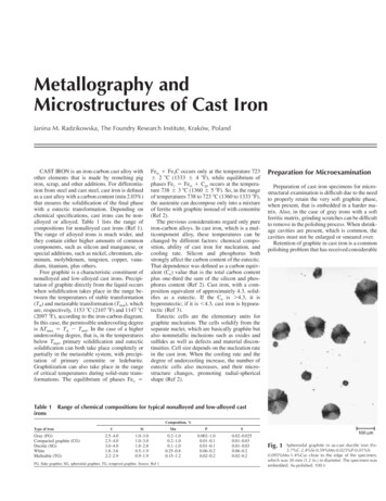
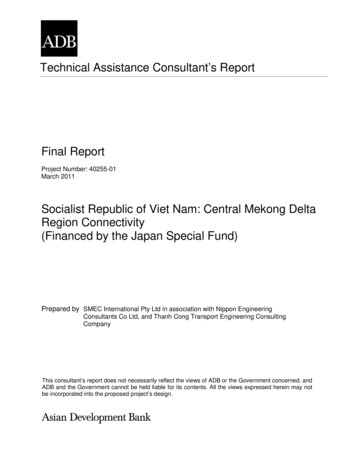
ii.iii.Replica strip was pressed firmly against the prepared sample surface for at least 30seconds so that clear impression of the specimen can be obtained for observationunder microscope.Prepared replica was fixed on a glass slide by removing its back cover tape.Figure 2: Transcopy Replica Kit2.4 Microstructural Analysis and Interpretation of ResultsMicrostructural observation is the key step for which all the specimen preparation and replicationis done. It is the step which reveals type of microstructure and the extent of damage sustained bythe component since it went into service. Crack determination is important to help establish theroot cause of a potential failure in a component. Creep defects cause the majority of failures inpower plant components operating under stress and thermal load, and the replica method isespecially suitable for the detection of these defects. The detection of various deleteriousprecipitates in components subjected to high temperature and stress can lead to improved lifeassessment analysis of these components.Prepared replicas were viewed by using portable microscope and were compared with actualmicrostructure of the specimens as shown in figure 3. Basic technique of utilizing the equipmentfor preparation and observation of replicas has been practiced whereas interpretation of resultswill require the team to be trained at advanced level to interpret the results.3
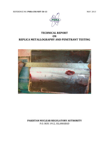
Figure 3: Micrographs; Specimen (Left) and Prepared Replica (Right)3. LIQUID PENETRANT TESTING (PT)Liquid penetrant inspection is a method that is used to reveal surface breaking flaws by bleed out of acolored or fluorescent dye from the flaw. The technique is based on the ability of a liquid to be drawninto a "clean" surface breaking flaw by capillary action. After a period of time called the "dwell," excesssurface penetrant is removed and a developer applied. This acts as a blotter. It draws the penetrant fromthe flaw to reveal its presence. Colored (contrast) penetrant require good white light while fluorescentpenetrant need to be used in darkened conditions with an ultraviolet "black light"3.1 Basic Steps PTSurface Preparation: One of the most critical steps of a liquid penetrant inspection is the surfacepreparation. The surface must be free of oil, grease, water, or other contaminants that may preventpenetrant from entering flaws. The sample may also require etching if mechanical operations such asmachining, sanding, or grit blasting have been performed. These and other mechanical operations cansmear metal over the flaw opening and prevent the penetrant from entering.Penetrant Application: Once the surface has been thoroughly cleaned and dried, the penetrant materialis applied by spraying, brushing, or immersing the part in a penetrant bath.Penetrant Dwell: The penetrant is left on the surface for a sufficient time to allow as much penetrant aspossible to be drawn from or to seep into a defect. Penetrant dwell time is the total time that the penetrantis in contact with the part surface. Dwell times are usually recommended by the penetrant producers orrequired by the specification being followed. The times vary depending on the application, penetrantmaterials used, the material, the form of the material being inspected, and the type of defect beinginspected for. Minimum dwell times typically range from five(5) to sixty (60) minutes. Generally, thereis no harm in using a longer penetrant dwell time as long as the penetrant is not allowed to dry.4
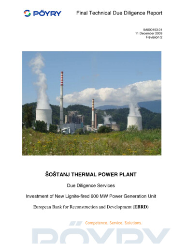
Excess Penetrant Removal: This is the most delicate part of the inspection procedure because the excesspenetrant must be removed from the surface of the sample while removing as little penetrant as possiblefrom defects. Depending on the penetrant system used, this step may involve cleaning with a solvent,direct rinsing with water, or first treating the part with an emulsifier and then rinsing with water. Thesesteps are shown in figure 4.Figure 4: Application of penetrant after surface preparationDeveloper Application: A thin layer of developer is then applied to the sample to draw penetrant trappedin flaws back to the surface where it will be visible. Developers come in a variety of forms that may beapplied by dusting (dry powdered), dipping, or spraying (wet developers).Indication Development: The developer is allowed to stand on the part surface for a period of timesufficient to permit the extraction of the trapped penetrant out of any surface flaws. This developmenttime is usually a minimum of 10 minutes. Significantly longer times may be necessary for tight cracks.5
Figure 5: Indication development after application of developerInspection: Inspection is then performed under appropriate lighting to detect indications from any flawswhich may be present.Liquid penetrant inspection can only be used to inspect for flaws that break the surface of thesample. Some of these flaws are listed below: Fatigue cracksQuench cracksGrinding cracksOverload and impact fracturesPorositySeamsPin holes in weldsLack of fusion or braising along the edge of the bond line6
Figure 6: Inspection of indication and position measurementClean Surface: The final step in the process is to thoroughly clean the part surface to remove thedeveloper from the parts that were found to be acceptable.3.2 Advantages and Disadvantages of Penetrant TestingLike all nondestructive inspection methods, liquid penetrant inspection has both advantages anddisadvantages. The primary advantages and disadvantages when compared to other NDE methods aresummarized below:Advantages: The method has high sensitivity to small surface discontinuities.The method has few material limitations, i.e. metallic and nonmetallic, magnetic andnonmagnetic, and conductive and nonconductive materials may be inspected.Large areas and large volumes of parts/materials can be inspected rapidly and at low cost.Parts with complex geometric shapes are routinely inspected.Indications are produced directly on the surface of the part and constitute a visualrepresentation of the flaw.Aerosol spray cans make penetrant materials easily portable.Penetrant materials and associated equipment are relatively inexpensive.7
Disadvantages: Only surface breaking defects can be detected.Only materials with a relatively nonporous surface can be inspected.Pre-cleaning is critical since contaminants can mask defects.Metal smearing from machining, grinding and grit or vapor blasting must be removedprior to LPI.The inspector must have direct access to the surface being inspected.Surface finish and roughness can affect inspection sensitivity.Multiple process operations must be performed and controlled.Post cleaning of acceptable parts or materials is required.Chemical handling and proper disposal is required.4. CONCLUSIONTwo experiments were performed each by Replica Metallography and Penetrant Testing technique.Penetrant testing experiment was performed successfully as a whole. It is to be noted thatgrinding/polishing of specimens was not possible due to inoperable condition of portable polishing unit.Steps should be taken to ensure that this equipment is in operational condition. On the plus side the basicprocess of replication and microscopy was performed on already polished samples available in the lab.Advance steps of Metallography i.e. interpretation of results require advanced level of training and skill inthe field of physical metallurgy and require more sophisticated tools.FUTURE TASKSThe future tasks include specialized training on:i.ii.Use of Coating thickness gaugeUse of Universal hardness tester8
replication. In Situ, Replication Metallography utilizes portable grinding and polishing unit to serve this purpose. Grinder/Polisher unit is shown in figure 1. Figure 1: Portable Grinder/Polisher Note: 2.3Preparation of R eplica During work at NDT Lab SNRS these steps were omitted because the equipment was not in working condition. Instead already prepared specimens were used for