Transcription
9INJURY BIOMECHANICS RESEARCHProceedings of the Thirtieth International WorkshopDevelopment of Finite Element Human Neck Modelfor the SIMON ProgramH.Y. Choi, I.H. Lee, E. Haug, E. Takhounts, and R. EppingerThis paper has not been screened for accuracy nor refereed by any body of scientific peersand should not be referenced in the open literature.ABSTRACTA finite element model development of a 50th percentile male cervical spine is presented in thispaper. The model consists of rigid, geometrically accurate vertebrae held together with deformableintervertibral disks, facet joints, and ligaments modeled as a series of nonlinear springs. Thesedeformable structures were rigorously tuned, through failure, to mimic existing experimental data;first as functional unit characterizations at three cervical levels and then as a fully assembled cspine using the experimental data from Duke University and other data in the NHTSA database.The validated model is intended for use as a post processor of dummy measurement within thesimulated injury monitor (SIMon) concept being developed by NHTSA where measured kinematicsand kinetic data obtained from a dummy during a crash test will serve as the boundary conditionsto “drive” the finite element model of the neck. The post-processor will then interrogate the modelto determine whether any ligament have exceeded its known failure limit. The detailed informationof structures and validation process of the anatomical human neck model used for the SIMonprogram will be presented.INTRODUCTIONFor the crash injury assessment of vehicle occupants, anthropometric test devices such as crashdummies are commonly employed both in experimental and numericalstudies. Displacements, accelerations and forces measured on crash dummy constitute injurycriteria which statistically quantify the potential degrees of injuries. Recently, the modeling ofhumans in the numerical crash simulation is widely in progress in parallel with the attempts ofdesign enhancement of current crash dummies for the better biofidelity and measuringcapabilities. Numerical try-out with human models in the crash simulation is somewhat favorablesince it can provide the basic injury mechanisms and also can predict real crash injuries such asbone fractures and ligament ruptures. However, the injury assessment using numerical humanmodel has not yet obtained general legitimate approvals. The concept of simulated injury monitor,SIMon originally proposed by NHTSA, fills the gap between two different applications in injuryassessment using crash dummies and numerical human models. Crash dummy measurements, suchas neck loads and kinematics of head and torso, are the external input conditions for the calculationof responses of the anatomical human neck model in the SIMon neck program. Thus, the SIMon115
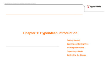
Injury Biomechanics Researchneck program consists of PC Window based finite element solver, anatomic human neck model,and the graphic interface. In this paper, the detailed information of structures and validationprocess of the anatomical human neck model used for the SIMon program will bepresented. Newly proposed neck injury criteria from this study, based on the degrees ofligament and disc ruptures, will be analyzed in comparison with Nij neck injury criteria.FINITE ELEMENT MODELING OF HUMAN NECKThe model, anatomically depicted in detail, was built on 50% male geometry. The hard andsoft tissues in the neck such as vertebrae, muscles, ligaments, organs, discs and fatty tissues weremodeled by using the various kinds of finite elements and material properties to represent adequatemechanical behaviors of each component. Figure 1 shows the SIMon neck model developed in thisstudy.Figure 1: Finite element human neck model for SIMon programCervical VertebraeThe geometry of vertebrae was adopted from Viewpoint DatalabTM (VP2488: Points-11025,polygons-15726, www.viewpoint.com). Figure 2 is the corresponding 3-D CAD drawing in IGESformat. From Figures. 3 to 5, selected finite element models of cervical vertebrae are shown withcorresponding anatomical features. Since the each vertebra bone was modeled as a rigid body,geometrical inertia characteristics such as center of gravity, mass moment of inertia and mass arerequired. These kinematic properties (Table 1) were calculated based on the cross sectionalgeometries and different densities of bony external (cortical bone) and internal (trabecular bone)structure of cervical vertebrae.116
Development of Finite Element Human Neck Model for the SIMON Program(a) posterior view(b) front view(c) lateral viewFigure 2: Three-dimensional CAD drawing in IGES format [2]anterior seprocessfovea for denssuperiorarticular facettransverseforamenposterior tubercle(a) anatomy (Gray, 1918)(b) SIMON neckFigure 3: Atlas (C1)odontoid process(dens)posterior articularsurfacebody of axistransverseprocesstransverseprocessspinous process(a) anatomy (Gray, 1918)(b) SIMON neckFigure 4: Axis (C2)117
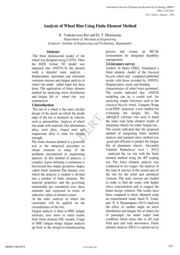
Injury Biomechanics Researchspinous processvertebral archposteriortubercleposteriortuberclesuperior articularprocessbody of vertebraanterior tubercle(a) anatomy (Gray, 1918)anterior tubercle(b) SIMON neckFigure 5: 5th cervical vertebra (C5)Table 1. Mass And Inertia Properties Of Cervical Vertebrae In The SIMON Neck2Inertia (kg/mm )VertebraMass 82.8862.5844.797(r, s, t represent the principal axes, front, lateral and superior directions, respectively)Intervertebral DiscsEach disc is composed of nucleus pulposus, annulus fibrous, and cartilageous end-plate.Between 70 to 90 % of the nucleus pulposus by weight is water, and takes up as much as 40 to60 % of the disc area. The annulus fibrous is a laminated and hence anisotropic structurecomposed of several layers in which each layers maintain a 30 degree angle of inclination from thehorizontal plane. The inner boundary of the annulus fibrous is attached to cartilageous end-plate,and the outer surface is directly connected to vertebra body. The discs play dominant role insustaining the body against compressive load. The discs show greater stiffness for thefront/rearward motions than for the side/side motion, with the annulus fibrous rather the nucleuspulposus making a major contribution. In SIMon neck model, complex deformation of the discswas modeled by using 6-DOF kinematic joint element. For defining the kinematic joint elements,three translational force-deflection and three rotational moment-angle relations are needed. Basicinformation for these relationships was adopted from reported experimental measurements (Pintar,1986, Yoganandan, et al, 2001, Moroney, 1998). Figure 6 shows the mechanical properties appliedto 6 DOF kinematic joint element of disc between C4 and C5.118
Development of Finite Element Human Neck Model for the SIMON Programfrontal viewlateral al/lateral (kN-mm)Fore/aft (kN-mm)202515201015Tension/compression -0.5100.51-10-10-20-15-15-20-20-30Torsion (Nm-radian)Lateral bending (Nm-radian)Figure 6: DOF mechanical properties of disc between C4 and C5LigarmentsA ligament is one of the two connecting tissues for the human cervical spine. Its functionis to ensure that the spinal motion occurs within some physiological bound, thus preventing spinalcode injury due to excessive spinal motion. The ligament is usually situated between the twoadjacent vertebrae, and in some cases, even connects several vertebrae. While the ligament showshigh strength against tension along the axial direction, it cannot support much compressive load.To account for the visco-elastic and anisotropic biomechanical properties of the ligament, nonlinearone dimensional bar element that can support only tensile load was used for the numericalsimulation purpose. For cruciform, transverse, and tectorial ligaments in atlanto-axial jointhowever, membrane elements were used instead to allow for surface contact. Figures 7 through 11show selected finite element models of ligaments with corresponding anatomical features.119
Injury Biomechanics Researchanterior longitudinalligamentatlasaxis1st intervertebral discC3(a) anatomy (Gray, 1918)(b) SIMON neckFigure 7: Articulations of occipital bone and C1 C3 (front view)occipital boneposterior atlantooccipital membranearticularcapsulesaxis(a) anatomy (Gray, 1918)axis(b) SIMON neckFigure 8: Occipital-atlanto-axial joints (posterior view)alar ligamentsapical ligament of densalar ligamentsdens of axisarticular capsulesarticular capsules(a) anatomy (Gray, 1918)(b) SIMON neckFigure 9: Alar and apical ligaments (posterior view)cruciform ligamentalar ligamentalar ligamenttransverse ligament(a) anatomy (Gray, 1918)(b) SIMON neckFigure 10: Atlanto-axial joints (posterior view)120
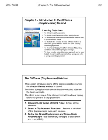
Development of Finite Element Human Neck Model for the SIMON Programtectorial membraneatlasaxis(a) anatomy (Gray, 1918)(b) SIMON neckFigure 11: Median section of atlanto-axial jointsA typical behavior of the ligament under tensile load is shown in Figure 12 (Yoganandan,2001). OA denotes the ambient phase or toe region representing a highly non-linear curvecorresponding to low stiffness; AB denotes the most linear phase (these two correspond tophysiologic loading); BC denotes the traumatic phase (region of gradually decreasing stiffness); Cdenotes failure. Post-traumatic phase is represented by the portion of the curve beyond thetraumatic phase (arrow). OA1, A1B1, B1C1 denote the stiffness pattern in these phases. At the pointof failure, the stiffness is zero. The physiologic, traumatic, and post-traumatic phases wererenamed as neutral, elastic, and plastic zones, respectively.As shown in Figures 7 through 11, each ligament was modeled by parallel connections ofmultiple single-bar elements. Thus, the reactive force existing in each ligament is a sum of forcesdeveloped by individual elements constituting that ligament. The damping effect in the ligamentwas modeled by viscoelastic characteristics (Nitsche, 1996) shown in Figure 13Figure 14 shows the force-deformation curves of C2/C3 ligaments applied in SIMon neckmodel. Each curve has bi-linear regions which represent the neutral and elastic stiffnesses. Thestiffness values are based on the segmental test results (Pintar, 1986, Yoganandan, et al, 2001, deJagor, 1996).Figure 12: Schematic drawing of tensile behavior of ligament (Yoganandan, 2001)121
Injury Biomechanics ResearchForce(kN)0.15Lengthening velocity(mm/ms)Figure 13: Damping factors for cervical ligaments0. 080. 080. 080. 070. 070. 070. 060. 060. 060. 050. 050. 050. 040. 040. 040. 030. 030. 030. 020. 020. 020. 010. 010. 010. 000. 02. 04. 06. 08. 010. 00. 000. 000. 0Anterior longitudinal ligament2. 04. 06. 08. 00. 010. 00. 080. 080. 070. 070. 070. 060. 060. 060. 050. 050. 050. 040. 040. 040. 030. 030. 030. 020. 020. 020. 010. 010. 010. 000. 002. 04. 06. 08. 010. 04. 06. 08. 010. 0Facet joint capsular0. 080. 02. 0Posterior longitudinal ligament0. 000. 02. 04. 06. 08. 010. 00. 01. 02. 03. 04. 05. 06. 07. 08. 09. 010. 0Ligament flavaInter-Spinous LigamentInter-Transverse LigamentFigure 14: Force-deformation curves of C2/C3 ligamentsMusclesTwenty two pairs of cervical muscles listed in Table 2 were included in the model. Onedimensional bar elements were used for each muscle segment (Figure 15). Depending on itsanatomical shape, single element or multiple elements serially joined were attached at the originand insertion points of relevant skeletons. Hill’s muscle model was utilized to generate both activeand passive muscle forces. The muscle activation level was assumed to be the same for allmodeled muscles and the degree of activation was set to correctly predict available humanvolunteer experimental data from NBDL and JARI.LocationsAnterior (flexors)Posterior (extensors)Table 2. List of cervical muscles in SIMon neck modelMusclesLongus colli, Longus capitis, Scalenus anterior,Scalenus medius, Scalnus posterior, SternocleidomastoidSplenius capitis, Splenius cervicis, Semispinalis capitis,Semispinalis cervicis, Longissimus capitis, Longissimus cervicis,Multifidus cervicis, Levator scapulae , Rectus capitis anterior,122
Development of Finite Element Human Neck Model for the SIMON ProgramRectus capitis lateralis, Rectus capitis posterior major,Rectus capitis posterior minor, Obliquus capitis superior,Obliquus capitis inferior, Trapezius, RotatoresFigure 15: Muscles in SIMon neck modelVALIDATIONSThe SIMon neck model has been validated against available experimental data. Thefunctional motion units at three cervical levels were chosen for both bending and tensile behaviors.Then, fully assembled c-spine under the tensile loading was simulated for the validation of overallcompliance of the cervical spine.Tensile and bending responses for functional cervical spine unitsFor validation of tensile stiffness and failure load of SIMon neck model, test results ofunembalmed human cadaver performed by Duke University (Myers, 2002) were used. In the Duketest, three functional motion units (FMU), OC/C2, C4/C5 and C6/C7 were placed in a testingdevice designed to apply pure vertical loads. Figure 16 shows the loading and boundary conditionsin the simulation which are equivalent to the test condition.As we can see from Figure 17, simulation result with SIMon neck model correlates wellwith the test results. The similar correlations were obtained from other two FMU simulations.123
Injury Biomechanics ResearchCOG of Upper VertebraFreeCOG of Lower VertebraFreeLoad CellFreeother directionsare all fixedForce : 1000 N/secFigure 16: Tensile loading and boundary conditions for FMU simulationFigure 17: Comparison of tensile force-deflection at C4/C5 FMU between test and simulation124
Development of Finite Element Human Neck Model for the SIMON ProgramCompliance test of extension and flexion performed by Duke University in series withabove mentioned tension test was utilized to verify bending characteristics of the model. In theDuke test, three functional motion units, OC/C2, C5/C6 and C7/T1 were placed in a testing devicedesigned to apply pure bending moment. Figure 18 shows the loading and boundary conditions inthe simulation which are equivalent to the test condition.Follower Force90 Nm/secFollower Force90 Nm/secLoad CellCOG of Upper VertebraCOG of Lower VertebraAll dirctions fixedFigure 18 Bending and boundary conditions for FMU simulationFigure 19: Comparison of bending moment-angle at C5/C6 FMU between test and simulationAs we can see from Figure 19, simulation result with SIMon neck model correlates well with thetest results. The similar correlations were obtained from other two FMU simulations.125
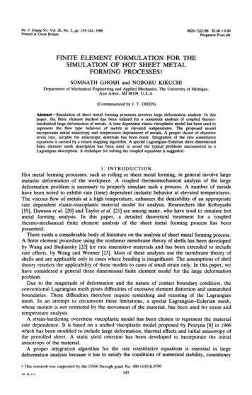
Injury Biomechanics ResearchTensile responses for whole cervical spineThe tensile compliance of whole cervical spine was simulated with two kinds ofend conditions. Figure 20 shows the loading and boundary conditions in the simulation which areequivalent to the test condition.Fixed(ECFX), Free(ECFF)COG of HeadOther directions fixedFixed all directionsexcept loading directionForce : 200 N/secFigure 20: Loading and boundary conditions for WCS simulation(a) Fixed-Fixed end condition(b) Fixed-Free end conditionFigure 21: Comparison of force-deflection relationship of WCS between test and simulationAs shown in Figure 21, the global stiffness of whole cervical spine of SIMon neck modelshows considerably smaller values in both end conditions in comparison with Duke testmeasurements.126
Development of Finite Element Human Neck Model for the SIMON ProgramCONCLUSIONSThe poor correlations of SIMon neck model for whole cervical spine tensile characteristicsare mainly due to the effects of extra compliance and frictions at fixation and frames in test. Byaccounting for those effects which was quantified by Duke University (Nightingale, 2003) in themodel, the prediction for the compliance of WCB becomes substantially improved as shown inFigure 22. The details of model reformation to take those extra compliance and frictions intoaccount will be introduced at the next workshop.Figure 22: Comparison of force-deflection relationship of WCS between test and simulation(recalculated for Fixed-Fixed case with updated model)127
Injury Biomechanics ResearchACKNOWLEDGEMENTSThis study was supported, in part, by Korean ministry of science and technology. (ProjectNo.: M10139080001-02B0808-00210)REFERENCESDE JAGER, MARKO (1996) Mathematical Head-Neck Models for Acceleration Impacts, Ph.D.thesis, University of Technology,GRAY, H. (1918) Anatomy of the human body, Lea & Febiger,NITSCHE, S., HAUG, E. and KISIELEWICZ, L. T. (1996) Validation of a Finite Element Model ofthe Human Neck, ESI GroupMORONEY, S. P., SCHULTZ, A. B., MILLER, J. A. A., ANDERSSON, G. B. J. (1998)Load- displacement properties of lower cervical spine motion segments, Journal ofBiomechanics, Vol. 21, No. 9, pp. 769 779MYERS, B. (2002) personal communicationNIGHTINGLALE, R. (2003) personal communicationPINTER, F. A. (1986) The biomechanics of spinal elements, Ph.D Thesis, Marquette University,YOGANANDAN, N., KUMARESAN, S., PINTAR, F. A. (2001) Biomechanics of the cervical spinePart 2. Cervical spine soft tissue responses and biomechanical modeling, Clinical BiomechanicsVol. 16, pp1 27128
Numerical try-out with human models in the crash simulation is somewhat favorable since it can provide the basic injury mechanisms and also can predict real crash injuries such as . Three-dimensional CAD drawing in IGES format [2] (a) anatomy (Gray, 1918) (b) SIMON neck Figure 3: Atlas (C1) (a) anatomy (Gray, 1918) (b) SIMON neck .