Transcription
ANALYSIS OF SHELLS AND FOLDED PLATE STRUCTURESBY FINITE ELEMENT METHODByf,1, S. BHATA Thes·isSubmitted to The Faculty of Graduate Studiesin Partial Fulfilment of the Requirementsfor the DegreeMaster of EngineeringMcMaster UniversityAugust,1969
MASTER OF ENGINEERING (1969)McMASTER UNIVERSITY(Mechanical Engineering)Hamilton, Ontario.TITLE: ANALYSIS OF SHELLS AND FOLDED PLATE STRUCTURESBY FINITE ELEMENT METHODAUTHOR: M. S. BHAT, B.E.(University of Mysore)S.UPERVISER: PROFESSOR J. N. SIDDALLNUMGEH OF PAGES:SCOPEA JD119COfHENT:A computer program is written to calculate thedeflections and stresses in a shell of general nature.An oblique. truncated pyram·id, built of alu111iniumolates is used for illustration and experimentalanalysis.Theoretiial values of deflections and stressesare compared with the experimental .results.II
ACK N0 \·IL EDGE ME NTSThe author gratefully acknowledges the assistanceand guidance of Professor J. N. Siddall and Dr. M.A.Dokainish in planning this project.The author feels indebted to the Department ofMechanical Engineering and the Canadian Armament Researchand Development Establishment for providing the opportunityto work on this project.III
TABLE OF CONTENTSPAGELIST OF ILLUSTRATIONSvAl3STIU\CTVIINTRODUCTIONTHE PHYSICAL MODEL6THEORETICAL ANALYSIS7COMPUTATION PROCEDURE AND COMPUTER PROGRAM31EXPERIMENTAL ANALYSIS39RESULTS AND CESIStiffness Matrix of aTriangul r74Element in Plane StressII Stiffness Matrix of a TriangularElement in Bending76III Computer programs79
LIST OFILLUSTRATIO SPAGE1. OVERM.L PICTURE OF THE SET UP462. PLAN473.ORIENTATION OF GLOBAL f\XE S484. DIVIS IO! INTO TRIANGULAR ELEMENTS495. I DE A.LI U1 TI ON OF THE SHELL516.PARTITIONING OF THE STRUCTURE7. GRAPHS( COMPUTED fffSULTS)v5556
ABSTRACTThis research program has the general objectiveof establishing analytical techniques for the analysis ofshells and structures built up of flat plates. The method.used is the finite element displacement method withtriangular plate elements.A program is written to calculate the deflectionand stress distribution in a shell of any configurationwith arbitrary boundary and loading conditions.To achieve reasonably small mesh size in a shell,the number of equations to be solved often becomes verylarge and hence, i t is necessary to devise specialtechniques that take advantage of the sparse nature ofthe stiffness matrix. The stiffness matrix is arrangedas a tridiagonal set of subrnatrices and solution isobtained by a method of recursion.W enallthe elements joining at a node are inthe same plane, the stiffness matrix must be partiallyassembled in local co-ordinates. This happens in foldedplate shells and the program is written to include suchcases.VI
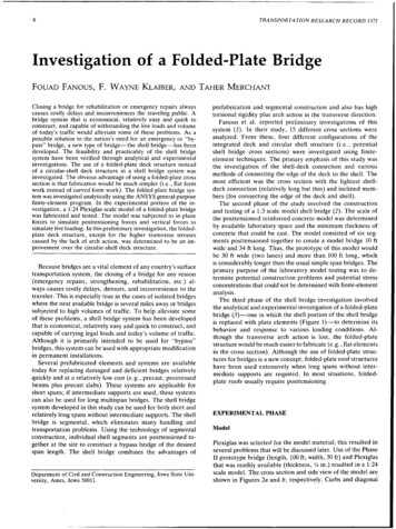
For experimental investigation, a foldedplate shell, resembling an oblique truncated pyramidwas built. The comrrnted values of deflections andstresses are compared with experimental results.VI I
l. INTRODUCTIONOne of the most important developments in thefield of structural analysis in the last decade is theapplication of finite element technique for stuctures,consisting of one, two, or three dimensional continua.The method nowadays is the most general and one of themost powerful tools for the analysis of structures.One of the greatest advantages is its versatality;the method provides a unified and integrated approachto the analysis of any type of structural assen;b-ly,from any field and any combination one, two and threedimensional elements of different characteristics.Problems presented by openings, anisotropy and variationof thickness are no longer of consequence, once generalprograms are written.[l]The method has been successfully used inaeronautical and civil engineering applications.Analysis of mechanical engineering structures has laggedbehind, perhaps because they are much more difficult tocategorise, and due to the nonavailability of a unifiedapproach for the analysis. With the advent of finiteelement method and high speed digital computers, analysisof such structures can be attempted.
2The present work has the general objectiveof extending the finite element procedure to shellsand folded plate structures. Such structures commonlyoccur in machine design in nonsterotype form. Previouswork in this project on space frames {one dimensionalbeam-like structures) was done by Tiwari [3] and Raghava[4], and an optimization study was done by Gurunathan [5].The finite element method is based on theconcept of idealizing a continuous structure into anassemblage of finite structural elements interconnectedat a finite number of nodal points.If the force displacementrelations at the norles of the elements can be foundand expressed ir, thf rriatrix form, by superposition ofthese elementstif nessmatrices the stiffness matrixof the entire structure can be found. Thus the method isbased on a physical rather than a mathematical approximat·ion.The properties of the elements recalculated using thetheor.Y of continuous elastic media, and an assumeddisplacement distribution inside the elements. If theassumed displacement function (or functions) satisfiescertain criteria, as the element size is decreased, thedeformational behaviour of the idealized structure convergesto that of the continuous structure.
3The concept was first introduced by Turner et al[2] in 1956. Since then the method has undergone rapiddevelopment, particularly in the last few years. A largenumber of research papers have been published in recentyears illustrating the application of the techniqueto different structural problems. The principle is alsobeing used in problems other than structural, such asheat conduction, fluid flow and distribution of electricand magnetic potential. A book by Zienkiewicz and Cheung[l] is comprehensive and useful.A shell may be considered to be made up of smallflat elements interconnected at a finite number ofnodal points. The element in a shell will be subject toboth in plane and bending forces. For a flat elementthese cause independent deformations, provided thesedeformations are small. Hence the stiffness matrix ofthe element can be evaluated seperately for in-planeand bending forces and combined together to get thestiffness matrix in the general case.In dividing an arbitrary shell into flat elementsonly triangular elements can be used. Although the conceptof the use of such elements was suggested as early asin 1961 by Greene et al [6], the success of such
4analysis was limited due to the lack of good stiffnessmatrix for triangular element in bending. A discussionon the existing methods for the evaluation of the bendingstiffness matrix and the considerations on which thepresent method was selected is given in section 3.To achieve reasonably small mesh size, in orderto get convergence to the true results, the number ofequations to be solved (or the size of the stiffness matrix)often becomes very large, so that conventional methodscah not handle the problem due to lack of sufficientcomputer central memory. Hence special methods making useof the sparse nature of the stiffness matrix must be devised.The program given in this report is based on partitioningtechnique and solution of the equations by a method ofrecursion.When all the elements joining at a particularnode are in the same plane, as it often happens infoldedp ateshells, the equations corresponding to theparticular node become linearly dependent and the stiffnessmatrix becomes singular. To overcome this difficulty,part of the stiffness matrix corresponding to such nodesmust be assembled in local co-ordinates. Detailedcomputation procedures are included.
5To confirm the validity of the method as appliedto folded plate shells of nonstereotyped configuration,an oblique four faced pyramid , made of aluminium plates.Deflections and stresses were measured at certain chosenpoints on the shell and results compared with the theoreticalresults.
62. PHYSICAL MODELFor experimental verification of the theoreticalresults obtained, i t was decided to examine a simplefolded plate shell. An oblique four faced truncatedpyramid was built of aluminium plates. Figure l gives theoverall picture of the set up. Figures 2 and 3 illustratethe dimensions. The obliquity of the shell ensuresassymmetry of static and dynamic response. The shell was, built up of 1/8 in. thick aluminium plates weldedtogether at the edges. The 4.5 in. square top was closedby a 1/2 in. thick plate. In the theoretical analysisof the shell, the bottom is considered to be rigidlyfixed. Hence, for .the accuracy of the results, it isimportant that the deflections· and rotations at the baseare small ornparedwith the relative displacements ofthe structure itself. At the base the plates are bent,,,,and bolted down to heavy cast iron bars 6 x 6 in section.l in. thick steel cover straps and lock-washers are usedto hold the base of the shell firmly down to the heavycast iron bars. The shell was loaded and the base wastested for possible movement with a dial gage. Nomovement was detected.
73.THEORETICAL ANALYSIS3. 1 lJiLRQ QJLCJLQiiThe basic concept of finite element method isthe substitution of an assemblage of discrete structruralelements for the actual continuum. The continuum isvisualized as made up of finite elements interconnectedat a finite number of nodal points, the materialproperties of the original structure being retained inthe elements.General procedure of obtaihingielement stiffnessmatrices of the elements is discussed in [J] and [7].The basic steps can be laid down as follows.(a) A function (or functions) is chosen to uniquelydefine the displacement distribution insideeach element in terms of its nodal displacements.{d} [N]{o} 1where:{d} displacements of a point inside the element.{6}1 nodal displacements of the element.[NJ a function of theco-ordinat.E. Sof the pointand the the assumed displacement function.(b) The strains are computed from the displacements.
8{d [B]{i}i(2){c) The stresses are calculated using [DJ, the linearelastic relation between stresses and strains.{cr} [D][B]{o}i{ 3)The product [D][B] is called the stress matrix.{d) The stiffness matrix [k] is obtained by equatingthe internal and external work.[k] r[BJ 1 [D][B]dV"The integrationmust be(4)carri dout throughout thevolume of the element.(e) The stiffness matrix obtained in localco-ordinatesis now transformed to global co-ordinates.Once element stiffness matrices of the structure arecomputed in global co-ordinates, the assembly and solutionof equations follow the standard pattern.The most important steps that govern the accuracyof the solutions are the physical approximation oridealization into a finite element system and the mannerin which the displacement patterns inside the elementsare defined. As already indicated, the first step afteridealization is the assumption that the deformationsinside each element are limited to a restricted pattern,and the accuracy of the solutions directly depend onthe extent to which these assumed patterns can approximate
9the state of deformation of the continuum.3 . 2 lll5P1JLCJ.t1EJ:l.J E1JHCTLOH5 In order to ensure that the results converge tothe true values as the mesh size 1s reduced, the assumptionsunderlying the finite element concept, i.e. the displacementfunctions assumed, must satisfy certain conditions. Thesufficient conditions as given by Brazely et al [8] area s f o 1 1 o 1·1 s .(l) The displacement function must be capable ofrepresenting constant strain conditions, includingzero strain corresponding to rigid body displacements.Otherwise the finite element idealization can notrepresent the true state strain, no matter howfine the mesh is made.(2) the displacement function must be such that thedisplacements and slopes are continuous or compatiblebetween adjacent elements along the boundaries.An element that satisfies the second condition atall stages is called conforming and it can be proved thatsuch idealization gives monotonic convergence to truedeformation pattern [9]. If discontinuities are caused atthe interfaces of the elements due to the nature of thedisplacement function chosen, infinite strains will result
l0at the boundaries. Nevertheless, if in the limit, as themesh size is decreased continuity is restored then, theformulation will still tend to the correct ans\'Jer. Therequirement of full conformity for triangular elements inbending makes computation difficulties rise disproportionatelyfast. In fact, for practical purposes, a better approximationcan be obtained for reasonably fine mesh size by usingnon-conforming polynomial shape functions.The in-plane and bending forces on a flat elementcan be considered separately. The in-plane displacementof each node has two components, hence there Jill be sixcomponents of displacement for each element.{6.}, p ( 5){ uv,,·.}whe re u 1. , v 1. a re the di s p l a c em e n ts o f n ode i i n t v!Operpendicular directions respectively. Let a triangle bedefined by three nodes i, j, k. Listing the displacementsof all the three nodes, we have,,u.6.{6}p-:::0.1,v.:::;,u.J.Jv.okUkvk·J(6)
llThe corresponding forces can be written as,p .p.p1X1yixjpyjpxkpykpP.{ F} tp - JpkpThe displacements of a point inside the triangle is definedby two linear polynomials.( 7)The six arbitrary constants can be expressed i·n terms ofthe nodal displacements. The strains can then be evaluatedfrom the relation,{ } rxJyycxy ClUClXavay( 8)EJ: Cly axThe general procedureo section 2.1 is followed, andmatrix [BJ will be independent of the co-ordinates (x,y)of the point, since the polynomials are of the first degree.The stiffness matrix can be worked out explicitlyin terms of the material properties and'the nodalco-ordinates. It is given in Appendix I. The size of the
l2matrix will be 6 by 6, since there are a total of sixdegrees of freedom for the element.The assumption of first degree linear polynomialshape functions is equivalent to the assumption of linearvariation of displacement along the boundaries. Thedisplacements along the boundaries will therefore dependonly on the displacements of the two nodes at the end ofeach edge.This ensures compatibility of displacements ona common boundary of two adjacent triangular elements.Analysis of plane problems by this method has beenvery successful and good approximation to correct resultsis reported even for coarse subdivisions. A computerprogram to analyse plane problems is given by Zienkiewicz[1]. The program·can deal with a completely general problem,consisting of external forces, distributed body forces,and prescribed displacements.3.4 TRIANGULAR ELEMENTS IN BENDINGKirchoff's theory of plate bending is assumedso that the deformation inside the element is completelydefined if the lateral displacement, w, is defined. Eachnode has three degrees of freedom, the lateral displacement,w and the two rotations, - oxand ey .(9)
13{6}9" b{ l)The rotations are given by'awex - Cly( l 0)ey awaxfor right handed system of axes.The strains are, a2 wxx- Z-;; X0( 11 )c,Cl 2 \. !xy -2z--- ax aySince the triangular plate element has a total of ninedegrees of freedom in bending, the stiffness matrix willbe 9x9.The evaluation of the bending stiffness matrixrequires the assumption of a distribution function for w.Since there are a total of nine nodal displacements, thedistribution function must contain nine arbitrary constants.Obviously the simplest would be a polynomial expressionin x and y. But a full cubic polynomial contains ten
14arbitrary constant;. Any omission must be madearbitrarily.The followingdisplaceme tfunctions have beensuggested.(1) Adini suggested the following form [14].The term xy is omitted. The omission of the uniform twistterm results in reduced stiffness and is found to givepoor results.(2) Tocher [10&11] tried two other assumptions in attemptingto obtain an improved triangular plate bending e1E:ment.The first of these is the assumption that the coefficientsof x 2v and xy 2 are the same. The synirnetry of the expressionshas been maintained by combining two cubic terms. Thispolynomial automatically satisfies compatibility of lateraldeflection on the boundaries of the elements, but does notsatisfy compatibility of slopes. This has been tried inplate bending and vibration problems and is found to givea fairly good approximation even for coarse subdivisions.(3)Tocher s second element stiffness matrix was obtained1by assl!rnin9 the complete ten term polynomial and reducingit to a nine degree freedom system by Ritz method. But
15this element has greatly increased flexibility and is foundto give poorer results.(4) An approach making use of the so-called areaco-ordinates was introduced by Brazely et al [8]. Thisalso is a non-conforming solution and fairly good resultsare obtained for plate problems.(5) Allthe above displacement functions do not satisfyslope compatibility along the edges. Clough and Tocher[12] suggested a method to achieve slope compatibilityby dividing the elements into subtriangles. This methodgives monotonic convergence to the true results, as theelements are refined, but for coarse subdivisions the ·results obtained are much inferior to tl1e non-conformingsolutions suggested in 2 and 4.(6) Another approach for obtaining a conforming solution,based on a fifth degree polynomial expression for w wasrecently introduced by Cowper, Lindberg, Koska and Olson[13] and this probably gives the best convergence. Howeverthis shape function requires six degrees of freedom (lateraldeflection w, two first derivatives of w and three secondderivatives) at each node. When a triangular element isconsidered as a part of a shell, it is necessary to assignthree more degrees of freedom at each node. Hence the method
l6would require nine degrees of freedom per node andobviously only coarse mesh can be used, giving poorerphysical representation of the shell. This method has sofar been developed only for right angled triangles.An excellent discussion on some of the abovemethods and illustrations from numerical results in platebending problems can be found in [12].From the above discussion i t can be seen thatthe only suitable methods for shells a re 2 or 4. Thepolynomial shape function suggested in 2 was used in th'epresent project. However the program can st i 11 be usedforanyother method of calculating the bending stiffnessmatrix, simply by changing the subroutine to calculatethe bending stiffness matrix.The shape function used is,( l 2)From (9) and (10) the relation between the nodaldiaplacements and the arbitrary constants (a 1 ,a 2 ,- - - a 9 )can be written in terms of the nodal co-ordinates.{cS} [C]{a}( l 3)where{a}::{a1,a2, . a J9
17We c 1n calculate the strains using relations (11)and we have,{c} [H]{a}( 1 5)From (14) and (15){t} [H][C-l] {6} ( 1 6)Comparing with (2),Substitution in (4) yields the stiffness matrix [k]b '[k]b [c-l]Tf[H]T[D][H]dV.[C-l].(17)"The inverse of the matr·ix [CJ must be obtained numericallyfor each triangular element. The matrix product inside thevolume integral can be explicitly worked out. It containssecond degree terms in x and y and can Ge easily integratedover the area of the triangle. Appendix II gives expressionsfor [C] , the product [H]T[D][H] and some integrationformulas.3.5 GROUPING OF IN-PLANE AND BENDING STIFFNESS MATRICESIn a shell, an element is subjected to bothin-plane and bending forces. For a flat element thesecause independent deformations. Hence the stiffness
18matrix can be obtained by separately evaluating thein-plane and bending stiffness matrices and grouping themtogether in proper order.While evaluating in-plane stiffness matrix twocomponents of forces and deflections each are consideredat each node.{F}.e, [k]P{o}ipp{ F. } :: Ppyx ,,·.J1 p{{o1. }p ( l 8){uv.i}.1Three components of forces and deflections each,are considered at each node in bending, and the relationsof the following fotm are obtained.{Fi}b ·1ZlM .p XlMy1.where Pz is the force in the Z direction, Mx and Myare the moments about the x and y axes respectively.and
l9(l9)The rotation ei does not enter as a parameter in eithermode. However, it is necessary to include this and afictitious couple M2 before transforming the stiffnessma t r i x i n to g l o b a 1 c o - o rd i n a t e s . S i n c e et a n d th e a c c om p a ny i n gcouple Mz do not enter the minimization procedure, anappropriate number of zeros are inserted in the rows andcolumns of the stiffness matrix corresponding to a1.Hence the combined nodal displacements are dfined as,u.1v1.Wi{o.} 1e .x1ey1.e Zl.orand corresponding forces arePxi{ F.} 1p .y1p .ZlMX1.Myl.MZl.
20orThe combined stiffness matrix will now be made up of thefollowing submatrices:000Cl0 -00·001001 IIt,Ii0a·1[kmn- - [kmn] f0JPIII3.6 TRP.NSFOR1,1ATION TO GLOBALThe in-plane and0[k0]bmn 0r0000( 2 0)00CO-O DiifilL bendin stiffness matrices arederived for local co-ordinate system with the x-y planecoinciding with the plane of the element. But, since allthe elements in the shell will not be in the same plane,the global axis system will not in general be the sameas the local co-ordinate system for the individualelements. Hence, before assembling the stiffness matricesof the elements to get the overall stiffness matrix, itisneces aryto transform these stiffness matrices to
21the global co-ordinates.The forces and displacements in the twoco-ordinates systems transform according to the followingrule.{o.} [T] {cS.}'11( 21 ){F;} [T] {Fi}' herethe quantities with a slash are referred to theglobal system and [T] is the 6x6 transformation matrix.(TJ [ .0andOJ .( 22 ) . · is the matrix of direction cosines.[ .] ( 23)lx, mx' nx are the direction cosines of the localx axis referred to the global axes. Similarly ly, my,ny and 1 2 ,m 2,nz are the direction cosines of the localy and z axes.The submatrices of the element stiffness ma.tr·ixtransform as f6llows.
22[kmn]1 [T ]T[k mn ][T]( 24 )All th e submatrices of the element stiffn ess matrix mustb e t ran s f o rme d to g l ob a l co - o rd i n a t e s . Howe v e r, \·1 h e n a 1 1. th e e l ement s j oining at a particular nod e are in the sameplane, a difficulty arises. If all the submatrices aretr aniforrne in th e usua l way, i n g l obalco- ordinates s i xequation s that are singu l ar will be obtained. This is due'.to the fact that only five· of the six equat ion s can bel inearly ind ependent, s i nce the rotation perpend icular toth e plane i s omitted . In such cas es only fiv e de gree sof freedom should eassigned to such nodes; the rotationperpendicular to th e pl ane must not be includ id . Th e f orcesand displace ments at such nod es shou l dber e tained inlocal co -o rdinat es .Consi der a t r ian gular eleme nt 1-2-3 in which 2is such a nod e.- At 2 the displac eme nts and forc e s arealw ays consid e red in lo cal co-ordinates) and the rot ationabout th e z axis at 2 i s not inc lu ded. Hence).[ k . ] b : 00022:o .0 .0. .0[ksi ze 5 x 5J::;22000:0:o:.· ( 25 )
23and00. 12 . :o . 0 . 00o:[k.0]P·0o: 00:.0o:o[k12J0b(26)0size: 6 x 5size: 5 x 6The submatrix [k 22 J is not transformed to globalco-ordinates. [k 12 J and [k 21 J are transformed as follows.[k12J' [T]T[k12J6x56x6 6x5( 2 7)and[k21J' [kz1][T]5x65x6 6x63. 7 ASSEMB11 QF H!E OVERALL STIFFNESS MATRIX1he element stiffness matrices are assembled toget the stiffness matrix of the entire structure, basedon the condition of equilibrium at the nodes.Each component of the external force {R 1 J, actingat a node must be equal to the sum of the comnonentforces, in the same direction shared by elements joiningat that node.
24(28)the summation being taken over all the elements connectedat i. Substituting forrn{R;} l(29)in the absence of distributed body forces and initialstrains, andn number of nodesN number of elements in the structure.If a particular element is not connected to node iit will not contain submatrix with an i suffix.Hence thesubm trix[Kim] of the assembled stiffnessmatrix is( 30)3.8 SOLUTION QFEQU \TIONSIf the stiffness matrix of the whole structurecan be calculated and stored in computer memory, thesolution can easily be obtained by inverting the matrixand multiplying by the load vector to get the nodaldeflections. Once the nodal deflections are known, thestresses inside each element can be calculated. But inanalysing shel"is one problem arises. As indicated earlier
25to obtain convergence to the true results, it is necessaryto refine the mesh. As a result, the number of nodalpoints will increase. Since six degrees of freedom areconsidered for each node, the total number of degreesof freedom will be six times the number of nodes. Clearlyas the number of nodes increase, the size of the stiffnessmatrix increases rapidly. Hence a direct assembly andinversion of the stiffness matrix .is limited by theavailable computer central memory. The naximum numberof nodes that can be considered is limited to aboutforty, for the CDC 6400 computer.The size of the subdivision, or the number ofnodal points necessary to obtain reasonably goodapproximation in a particular problem is not obvious.But an inference can be drawn by studying the convergenceof the results. The variations of the results obtainedfor successively refined mesh sizes gives an indicationto the convergence of the results. Where as it may bepossible to obtain convergence to the true resultswithin forty nodal points in certain cases, a muchlarger number of nodal points may be required to makean approximate representation of the shell.
26A representative diagram showing the orientationof the global axes is given in figure l. To study theconvergence of the results, the displacements of the pointsA,B,C and D are computed for different idealizations.Four different idealizations with 25, 29, 33 and 37nodal points are considered (figures 5a,5b,5c and 5d).The computed values of deflections for a load of 200 lbs.applied at the point L in the X direction, are tabulated·in tables 1a, lb, le and ld. The variations of the resultsare quite high and obviously a more refined mesh size isrequired.Methods to solve larger number of equationsin analysing multistory building structures are discussedin [16]. The method used in this project is the methodof 'tridiagonalization 1 which makes use of the sparsenature of the stiffness matrix. By dividing the tructureinto a number of partitions and by proper numbering ofthe nodes, the stiffnessmatri can be arranged in theform of a tridiagonal set of submatrices, which can becalculated and stored on magnetic tapes. The solution isthen obtained by a method of recursion. Only two of thesubmatrices are required to be in the central memory ofthe computer at a time. A program to analyse plane
27problems by this method is given by Zienkiewicz [l].The shell is divided into a number of partitions.The arrangement is illustrated in figure 6. The nodalpoints and elements are numbered in consecutive order.The assembled stiffness matrix will be in the tridiagonalform as follows.PIPIIpII IPN -1pNlKICI000CTKIICII.006 II .0TenKII I000n1000000I'1[ 31The equations can be split and written as follows.J
28From (32),(34)Substituting for {o 1 } in (33),[KII]-[CI]T[KI]-l[Cl] ){ 0 11l [CII]{oIII} {PII}-[CI]T[KI]-l{PI}(35)Let:[RII] ([KII]-[CI]T[KI]-l[CI]){P11l {PII}-[CI]T[KI]-l{PI}( 3 6)The following equation can now be written:( 3 7)f r om wh i c h { oII } ca n b e o b t.a i n e d an d s u b s t i tu t e d i n t o t h enext row equation [R 111 J and {P 111 1 . Such a process ofsubstitution and elimination can be continued untilthe last matrix equation is reached.[KN]{oN} {PN}(38)and {oN} can be obtained by direct inversion of [RN].Once{6N}is obtained other deflections can be calculatedby back-substitution in the equations.
29The following points concerning the method arenoteworthy.1. The entire stiffness matrix is not stored. Onlythe tridiagonal band is stored on magnetic tapes.2 . Due to symmetry, it is necessary to store only [Ci]T.and [Ki] but not [ ci ] .3. The matrices [Ri]-l and {Pif are stored on magnetictapes assoon as they are generated in the forwardelimination process and they are used later in thebackward substitution.4. Only two submatrices [Ki] and [Ci] are requiredat one time in the memory of the computer.5. Very little extra computer time is needed to obtainsolutions for more than one load condition.A computer program based on the above procedure toanalyse shells and folded plate structures is described inthe next section. The complete program is given inAppendix III.The partitioning scheme is shown Figure 6.Upto ten partitions were employed. The computed valuesof deflections for different number of partitions are
30tabulated in Tables 2a to 2d. Graphs are drawn withcomputed deflections versus the number of partitions.Much higher fineness is achieved by this method andthe improvemeni i11 the convergence con be observedfrom the above.Since the matrices are eliminated in blocks,there is no limit for the total number of partitionsinto which the structure can be divided. But, considerablestoraqeis required for storinq- [C.]and [K.]and for,11carrying out intermediate calculations. Hence, theband width of the matrix or the number of nodes in apertition is limited by the storage capacity of thecomputer. Though it is possible to divide the shell intomore than ten partitions, es the number of nartitionsincrease, the height of each partition decreases.the triangular elements become long ndHence narrow. It wasactually observed that the computed deflections varyby a larger amount from ten to twelve partions than fromeight to ten partitions. Hence the computed results for tenpartitions were selected for experimental verification,since, these arc m0st likely to bene restthe true values.
314. COMPUTATION PROCEDURE AND COMPUTER PROGRAM4.1I
field of structural analysis in the last decade is the application of finite element technique for stuctures, consisting of one, two, or three dimensional continua. The method nowadays is the most general and one of the most powerful tools for the analysis of structures.