Transcription
SHOOTING STARSWITCHABLE POLARITY 8 ELEMENT10/11 METER BEAMwww.macoantennas.net(815)2443500MACO tStreet,Mt.Carroll,IL61053Copyright 2009CharlesElectronicsLLC AllRightsReserved
MACO SHOOTING STARPARTS LISTPART ��40”DESCRIPTIONAluminum tubing swaged both endsAluminum tubing slotted one endAluminum tubing slotted both endsAluminum tubing2” boom to 2” mast pipeCopper wireFiberglass rodsGamma matchesGamma straps f/coax connectorsCoax connectors w/mounting nutCHECKLISTHARDWARE BAG#1U01N0314282”5/16”Plated u-boltsLock nutsHARDWARE BAG#2S01142”Plated saddlesHARDWARE BAG#3BE2P82”Element to boom mountsHARDWARE BAG um clampsPlastic caps – blackPlastic cap – blackMachine screwsSquare nutsPlastic caps – redLock washersGamma strapsFiberglass rod kit (4 screws)Instruction sheetWarranty sheetTip sheetPlease note: In an effort to keep the price on Maco Antennas down, we have decided not to clean up all theburrs and rough edges on the parts. We recommend that you deburr and clean up each part with files,sandpaper, etc. so that they go together easily. We are aware this needs to be done but have elected not todo it to save you the money we would have to add to the price of the kit for this service.Revised 05/09
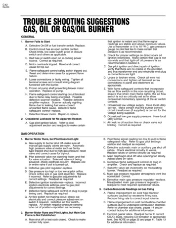
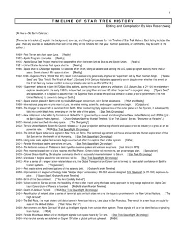
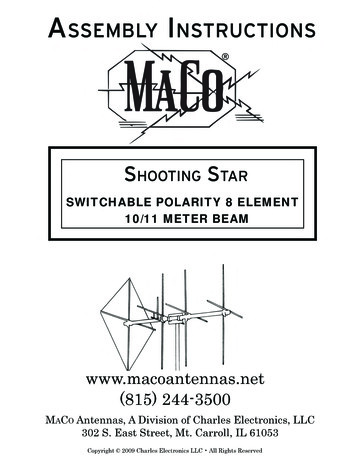
MAC0 SHOOTING STARASSEMBLY INSTRUCTIONSFIGURE 1GENERAL INSTRUCTIONSThis drawing depicts an overall view of what the antenna should look like upon completion ofassembly. Refer to Figures 2 thru4 for specific assembly details. All hardware should be coated with a siliconrubber sealant or a similar compound to insure that wind vibration does not cause it to work loose.FIGURE 2BOOM ASSEMBLYTo assemble the boom, slide the slotted ends of the boom sections (T51P) onto both swaged endsof the center boom section (T41P). Secure both joints with 2” U-bolts, saddles and hardware as shown indetail 2A.Next mark the boom center and mount the boom-to-mast plate (PO2P) using 2” U-bolts, saddles andhardware as shown in detail 2B.This antenna is designed for mounting on a 2” O.D. heavy duty mast. Mount using 2” U-bolts, saddlesand hardware as shown in detail 2C.FIGURE 3A ELEMENT ASSEMBLYPrior to assembling elements, slide a boom-to-element mount (BE2P) onto each of the 8 elementcenter section (T 11P).Assemble each element as shownusing the clamps and hardware specified. Refer to the element tableto determine dimensions for each element. Install a blackplastic cap (PL2) onto both ends of each element.Assemble the reflector elements in the same manner, sliding the fiberglass arms approximately 6inches into the ends of the center sections (T 11P). Snug the clamps, but don’t tighten them at this time becausethe arms will have to be adjusted after installing the reflector wire.FIGURE 3B ELEMENT MOUNTINGMark each element at the center and be sure that the boom-to-element mounts (BE2P) are centeredon the elements before tightening hardware.Starting 1 l/2” from the director end of the boom, mount each element using 2” U-bolts, saddles,boom-to-element mounts and hardware shown. Refer to Figures 1 and 3B for element spacing instructions.
FIGURE 3CREFLECTOR ASSEMBLYThe length ofthe reflector wire is very critical. REMEMBER: The Reflector dimensions are onlypreliminary. Change to get equal side of 9’ 6”. Fiberglass length is not critical, however, the equal wirelength of 9’ 6” is very critical. It must be the correct length to operate correctly. Take the wire (WO4P)and uncoil it making sure that there are no kinks; secure it to a nail. Pull the wire until it stretches an inchor so. The easy way to get the correct length for the reflector loop is as follows1. Drive 2 nails in a board or fence l/2 the length of the loop apart --which is 228” (5.79Om) betweenthem.2. Stretch the wire around the nails by hand as tightly as possible and splice ends together. Solderthe splice. Remove one nail and remove the loop. Cut any excess wire off.3. Loosely assemble the machine screws (S21), flatwashers (N26), lo&washers (N12), and hex nuts(NO6) onto the lugs of the fiberglass arms, adjusting the length as shown.4. Tighten 3 of the 4 clamps that hold the fiberglass rods.5. Install the wire as shown.6. Tighten the wire by pulling the fourth fiberglass rod until the wire is the same tightness as it wasaround the nails. The wire loop is now the correct length. Note the total length of the loopis critical, and also is the length of each side.FIGURE 4GAMMA MATCH MOUNTINGMount the (2) gamma matches (GOlP) to the horizontal and vertical driven elements, using thegamma straps (ZO2P, ZO8P) and attaching hardware as shown. Attach your 52 ohm coaxial cables to theconnectors (S42) and dress along boom and down the mast.ADJUSTING STANDING WAVE RATIORefer to Figure 4. The dimensions given are approximate and should be used as a starting point.The following instructions cover the adjustment ofone gamma match. To adjust the second gamma match,simply repeat this procedure.The gamma matchhas 2 adjustments. First is the capacitor adjust and the second is the slider adjust.Connect a S.W.R bridge to the coax between your transmitter and the antenna and check the S.W.R. Ifadjustment is required loosen the clamp on the gamma match and the screws holding the slider (GammaStraps ZO2P). Next move the capacitor adjustment first in one direction then the other until a minimumS.W.R. reading is obtained. If S.W.R. is not yet satisfactory, move the slider out 2” away from the boom.Ifthe reading has gone up, move the slider back to the original position and then 2” toward the boom. Nowreadjust the capacitor for minimum S.W.R. you should now be able to determine which direction to movethe slider. Repeat the above procedure moving the slider in smaller increments until a satisfactory S.W.R.reading is obtained. Tighten all hardware. Disconnect the S. W.R. bridge and reconnect your coaxial cable.3SHOOTING STAR
/REFLECTOR( S E E F I G . 3B)/DRIVEN ELEMENTS1 7 ’ - 5” ‘2/PL5 - BLACWPLASTIC CADIRECTIONO FRADIATIONGAMMA MATCHES (SEE FIG. 4)1stDIRECTORS17’‘22ndDIRECTORS I1 6 ’ - 6” “2//-PL2 - P L A S T I C - C A P(TYP. 12 PLACES)SHOOTING STARQsEETJNOTES:* 1. For details of boom assembly and mast mounting see figure 2.*2. For details of element assembly and mounting see figure 3.*3. Horizontal and vertical element spacing dimensions areidentical with l/4” gap between boom-to-element mounts.SHOOTLNG STAR4
/------w-----v----PO2P PLACB1I’III!II, T51P, BOOM, SECTIONBOOMIIIILUOI. SOI, NOI. N O 22” U-BOLT & SADDLE I51i6** N U T S a WSHRS. IL-------DETAIL 2A- - - - - -6’-----IISO-l, NOI, N O 22” U-BOLTS 8 SADDLES5/16” NUTS 8 WASHERS(TYPICAL 2 PLACES)I\L-------DETAIL 28- - e - ---------A- O”---.---e-mhIl- UOI,17,-o”/--------------------------- \UOI, SOI, NOI, N02,2” U-BOLTS 8 SADDLES5116” NUTS 8. WSHRS.7/ SHOOTING STARBOOM ASSEMBLYIIIIIL-BOOM WITHBOOM-TO-MASTPLATE ATTACHEDI,“CUSTOMERFURNISHED2” O.D. MASTIIDETAIL 2CSHOOTING STAR---J
A17’ 5”1ST DIRECTOR 17’2ND DIRECTOR 16’ 6”REFLECTOR13’ 2”ELEMENT\W58P, S21, NilCLAMP WITH #10-24x 112’SCREW 8 SQ. NUTW58P. S21. NilCLAMP WITH #IO-24 x 112”SCREW 8 SQ. NUTTllPl518” 0. DTUBINGDRIVENB5’ 8 l/2”5’ 6”5’ 3”3’ 7”The Reflector dimensions are onlypreliminary. Change to get equalside of 9’ 6”. Fiberglass length isnot critical, however, the equal wirelength of 9’ 6” is very critical.TUBINGPLZ------------ ELEMENTllPI ASSEMBLY (FIGURE 3A)7HORIZONTAL-4 b - - 1 / 4 -ELEMENTUOl, Sol, NOl. NO22” U-BOLT 8 SADDLE5/16” NUTS 8 WASHERSVERTICAL ELEMENT MOUNTINGUOl. s 01. NOl. NO22” U-BOLT 8. S’ADDLE5/16” NUTS 8 WASHERSuHORIZONTAL ELEMENT MOUNTINGELEMFNTSPACING(FIGURE 3B)----------------------------- -The Reflector dimensions are only preliminary. Change to get equal side of 9’tical, however, the equal wire length of 9’ 6” isTroubleshooting Tips at the end o:RITICALSHOOTING STAR6
* NOTE. THESE DIMENSONS ARE APPROXIMATE.iEFER TO THE lNSTRUCTIONS O NADJUSTINNG THE S.W.R. -1‘0 DETERMfNE EXA C T S E T T I N G S . THI:Rt: AKI:. 2 S E P A R A T EG A M M A ADJIJSI‘MtiNl‘S, I C‘Al’A(‘I’I‘OR ADJlJSTMEN’t‘, 2. SLIDEI POSl’fION.DO NOT MOVE BOTH AT THE SAME TIME.MOVE TtHl: CAPA ‘I’I‘OK FIRST, THEN, II: NE(‘t:SSAKY MOVI;‘l‘lIl: Sl.ll l;l , ANI) GO BACKTOTHE CAPACITOR.Z08P-GAM M A S T R A P S(INSTALL FLUSH AGAINSTBOOM-TO-ELEMENT MOUNT)USTOMER FURNISHEDOAXIAL C A B L E S/#10-24x112” S C R E W :‘w”,‘: :s I.:IIHORIZONTALDRIVENELEMENTI//3/Y” 24 NU I\3/R”STARWASHER‘\ s 4 2\f@ A STRAPS(SI IrxR)1L- GOlPHORIZONTALGAMMA MATCHVERTICALGAMMA MATCHSHOOTING STARGAMMA MATCH MOUNTINGQ?GizE3SHOOTING STAR
skillsandhaveinstalledsuppliedbyMACO towersormastswithouttheseknowledgeableskills.MACO s.net(815)2443500MACO 09/12/10
This antenna is designed for mounting on a 2” O.D. heavy duty mast. Mount using 2” U-bolts, saddles and hardware as shown in detail 2C. FIGURE 3A ELEMENT ASSEMBLY Prior to assembling elements, slide a boom-to-element mount (BE2P) onto each of the 8 element center section (T 11P). Assemble each element as shownusing the clamps and hardware specified. Refer to the element table .