Transcription
CIVL 7/8117Chapter 2 - The Stiffness MethodChapter 2 – Introduction to the Stiffness(Displacement) MethodLearning Objectives To define the stiffness matrix To derive the stiffness matrix for a spring element To demonstrate how to assemble stiffness matrices intoa global stiffness matrix To illustrate the concept of direct stiffness method toobtain the global stiffness matrix and solve a springassemblage problem To describe and apply the different kinds of boundaryconditions relevant for spring assemblages To show how the potential energy approach can be usedto both derive the stiffness matrix for a spring and solvea spring assemblage problemThe Stiffness (Displacement) MethodThis section introduces some of the basic concepts on whichthe direct stiffness method is based.The linear spring is simple and an instructive tool to illustratethe basic concepts.The steps to develop a finite element model for a linear springfollow our general 8 step procedure.1. Discretize and Select Element Types - Linear springelements2. Select a Displacement Function - Assume a variationof the displacements over each element.3. Define the Strain/Displacement and Stress/StrainRelationships - use elementary concepts of equilibriumand compatibility.1/32
CIVL 7/8117Chapter 2 - The Stiffness MethodThe Stiffness (Displacement) Method4. Derive the Element Stiffness Matrix and Equations Define the stiffness matrix for an element and thenconsider the derivation of the stiffness matrix for a linearelastic spring element.5. Assemble the Element Equations to Obtain the Globalor Total Equations and Introduce BoundaryConditions - We then show how the total stiffness matrixfor the problem can be obtained by superimposing thestiffness matrices of the individual elements in a directmanner.The term direct stiffness method evolved in reference tothis method.The Stiffness (Displacement) Method6. Solve for the Unknown Degrees of Freedom (orGeneralized Displacements) - Solve for the nodaldisplacements.7. Solve for the Element Strains and Stresses - Thereactions and internal forces association with the barelement.8. Interpret the Results2/32
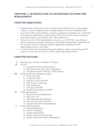
CIVL 7/8117Chapter 2 - The Stiffness MethodThe Stiffness (Displacement) Method1. Select Element Type - Consider the linear spring shownbelow. The spring is of length L and is subjected to anodal tensile force, T directed along the x-axis.f1xf2xNote: Assumed sign conventionsThe Stiffness (Displacement) Method2. Select a Displacement Function - A displacementfunction u(x) is assumed.u a1 a2 xIn general, the number of coefficients in the displacementfunction is equal to the total number of degrees of freedomassociated with the element. We can write thedisplacement function in matrix forms as: a u 1 x 1 x 2 1 a2 2 x 13/32
CIVL 7/8117Chapter 2 - The Stiffness MethodThe Stiffness (Displacement) MethodWe can express u as a function of the nodal displacementsui by evaluating u at each node and solving for a1 and a2. Boundary Conditionsu( x L ) u2 a2L a1 Solving for a2:u( x 0) u1 a1a2 u2 u1LSubstituting a1 and a2 into u gives: u u1 u 2 x u1 L x x 1 u1 u2 L L The Stiffness (Displacement) MethodIn matrix form:Or in another form: x u 1 L u N1x u1 L u2 u N2 1 u2 Where N1 and N2 are defined as:xN1 1 LN2 xLThe functions Ni are called interpolation functionsbecause they describe how the assumed displacementfunction varies over the domain of the element. In this casethe interpolation functions are linear.4/32
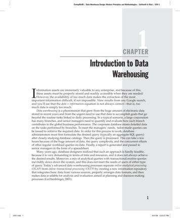
CIVL 7/8117Chapter 2 - The Stiffness Method5/32The Stiffness (Displacement) Methodu a1 a2 x x u 1 L u N2 1 u2 u N1N1 1 N2 x u1 L u2 xLN1 N2 1xLThe Stiffness (Displacement) Method3. Define the Strain/Displacement and Stress/StrainRelationships - Tensile forces produce a total elongation(deformation) of the spring. For linear springs, the forceT and the displacement u are related by Hooke’s law:f1xf2 xTTT k where deformation of the spring is given as: u(L ) u(0) u2 u1f1x Tf2 x T
CIVL 7/8117Chapter 2 - The Stiffness MethodThe Stiffness (Displacement) Method4. Step 4 - Derive the Element Stiffness Matrix andEquations - We can now derive the spring elementstiffness matrix as follows:Rewrite the forces in terms of the nodal displacements:T f1x k u2 u1 f1x k u1 u2 T f2 x k u2 u1 f2 x k u1 u2 We can write the last two force-displacement relationshipsin matrix form as: f1x k k u1 f2 x k k u2 The Stiffness (Displacement) MethodThis formulation is valid as long as the spring deformsalong the x axis. The coefficient matrix of the aboveequation is called the local stiffness matrix k: k k k k k 5. Step 4 - Assemble the Element Equationsand Introduce Boundary ConditionsThe global stiffness matrix and the global force vectorare assembled using the nodal force equilibrium equations,and force/deformation and compatibility equations.NK K k ( e )e 1NF F f ( e )e 1where k and f are the element stiffness and force matricesexpressed in global coordinates.6/32
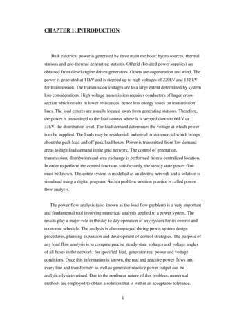
CIVL 7/8117Chapter 2 - The Stiffness MethodThe Stiffness (Displacement) Method6. Step 6 - Solve for the Nodal DisplacementsSolve the displacements by imposing the boundaryconditions and solving the following set of equations: F K d F Kd7. Step 7 - Solve for the Element ForcesOnce the displacements are found, the forces in eachelement may be calculated from:T k k u2 u1 The Stiffness Method – Spring Example 1Consider the following two-spring system shown below:where the element axis x coincides with the global axis x.For element 1: f1x k1 k1 u1 f3 x k1 k1 u3 For element 2: f3 x k 2 k 2 u3 f2 x k 2 k 2 u2 7/32
CIVL 7/8117Chapter 2 - The Stiffness MethodThe Stiffness Method – Spring Example 1Both continuity and compatibility require that both elementsremain connected at node 3.Element numberu3(1) u3(2)We can write the nodal equilibrium equation at each node as:F1x f1x (1)F3 x f3 x (1) f3 x (2)F2 x f2 x (2)The Stiffness Method – Spring Example 1Therefore the force-displacement equations for this springsystem are:F1x k1u1 k1u3Element 1F2 x k 2u3 k2u2Element 2F3 x k1u1 k1u3 k2u3 k 2u2 In matrix form the above equations are:0 F1x k1 k2 F2 x 0 F k k2 3x 1 k1 u1 k 2 u2 k1 k 2 u3 F Kdwhere F is the global nodal force vector, d is called theglobal nodal displacement vector, and K is called theglobal stiffness matrix.8/32
CIVL 7/8117Chapter 2 - The Stiffness Method9/32The Stiffness Method – Spring Example 1Assembling the Total Stiffness Matrix by SuperpositionConsider the spring system defined in the last example:The elemental stiffness matrices may be written for eachelement.For element 1:For element 2:u1u3 k k1 u1k (1) 1 k1 k1 u3u3u2 k k 2 u3k (2) 2 k 2 k 2 u2The Stiffness Method – Spring Example 1Write the stiffness matrix in global format for element 1 asfollows:(1) 1 0 1 u1 f1x k1 0 0 0 u2 f2(1)x 1 0 1 u3 f3(1)x For element 2:(1) 0 0 0 u1 f1x k 2 0 1 1 u2 f2(1)x 0 1 1 u3 f3(1)x
CIVL 7/8117Chapter 2 - The Stiffness MethodThe Stiffness Method – Spring Example 1Apply the force equilibrium equations at each node. f1(1) 0 F1x x (2) 0 f2 x F2 x f (1) f (2) F 3x 3x 3x The above equations give:0 k1 0k2 k1 k 2 k1 u1 F1x k 2 u2 F2 x k1 k2 u3 F3 x The Stiffness Method – Spring Example 1To avoid the expansion of the each elemental stiffnessmatrix, we can use a more direct, shortcut form of thestiffness matrix.u1 u3u3 u 2 k k1 u1k (1) 1 k1 k1 u3 k k 2 u3k (2) 2 k 2 k 2 u2The global stiffness matrix may be constructed by directlyadding terms associated with the degrees of freedom in k(1)and k(2) into their corresponding locations in the K asu1 u2u3follows: k1 0K 0 k2 k1 k2 k1 u1 k 2 u2 k1 k2 u310/32
CIVL 7/8117Chapter 2 - The Stiffness MethodThe Stiffness Method – Spring Example 1Boundary ConditionsIn order to solve the equations defined by the globalstiffness matrix, we must apply some form of constraints orsupports or the structure will be free to move as a rigid body.Boundary conditions are of two general types:1. homogeneous boundary conditions (the most common)occur at locations that are completely prevented frommovement;2. nonhomogeneous boundary conditions occur where finitenon-zero values of displacement are specified, such as thesettlement of a support.The Stiffness Method – Spring Example 1Consider the equations we developed for the two-springsystem. We will consider node 1 to be fixed u1 0. Theequations describing the elongation of the spring systembecome: k1 0 F1x 0 k1 0 k 2 u2 F2 x k2 k1 k 2 k1 k 2 u3 F3 x Expanding the matrix equations gives:F1x k1u3 Solve for u2 and u3F3 x k 2u2 k1 k 2 u3 F2 x k2u3 k2u211/32
CIVL 7/8117Chapter 2 - The Stiffness MethodThe Stiffness Method – Spring Example 1The second and third equation may be written in matrix formas: k 2 u2 F2 x k2 k k k u F 2 3 2 1 3x Once we have solved the above equations for the unknownnodal displacements, we can use the first equation in theoriginal matrix to find the support reaction.F1x k1u3For homogeneous boundary conditions, we can delete therow and column corresponding to the zero-displacementdegrees-of-freedom.The Stiffness Method – Spring Example 1Let’s again look at the equations we developed for the twospring system.However, this time we will consider a nonhomogeneousboundary condition at node 1: u1 .The equations describing the elongation of the springsystem become:0 k1 F1x k1 0k2 k 2 u2 F2 x k1 k 2 k1 k 2 u3 F3 x Expanding the matrix equations gives:F1x k1 k1u3F2 x k2u3 k2u2F3 x k1 k1u3 k2u3 k2u212/32
CIVL 7/8117Chapter 2 - The Stiffness MethodThe Stiffness Method – Spring Example 1By considering the second and third equations becausethey have known nodal forces we get:F2 x k2u3 k2u2F3 x k1 k1u3 k2u3 k2u2In matrix form the above equations are: k 2 u2 F2 x k2 k k k u F k 2 3 1 2 1 3xFor nonhomogeneous boundary conditions, we must transferthe terms from the stiffness matrix to the right-hand-side forcevector before solving for the unknown displacements.The Stiffness Method – Spring Example 1Once we have solved the above equations for the unknownnodal displacements, we can use the first equation in theoriginal matrix to find the support reaction.F1x k1 k1u313/32
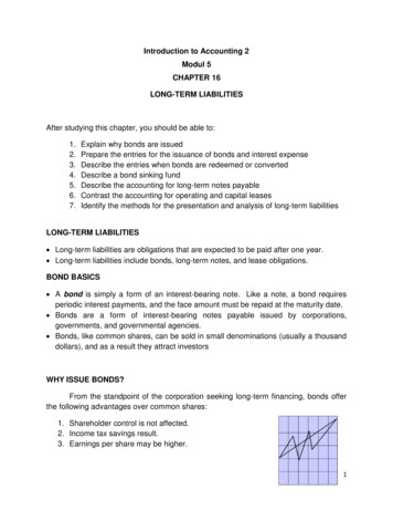
CIVL 7/8117Chapter 2 - The Stiffness Method14/32The Stiffness Method – Spring Example 2Consider the following three-spring system:The elemental stiffness matrices for each element are:133 1 1 k (1) 1000 1 1 4134 1 1 k (2) 2000 1 1 342 1 1 k (3) 3000 1 1 42The Stiffness Method – Spring Example 2Using the concept of superposition (the direct stiffnessmethod), the global stiffness matrix is:Element 10 10000 1000 030000 3000 K 100003000 2000 3000 2000 5000 0Element 3Element 2The global force-displacement equations are: 100000 u1 F1x 1000 0 3000 u2 F2 x 30000 100003000 2000 u3 F3 x 3000 2000 5000 u4 F4 x 0
CIVL 7/8117Chapter 2 - The Stiffness MethodThe Stiffness Method – Spring Example 2We have homogeneous boundary conditions atnodes 1 and 2 (u1 0 and u2 0).The global force-displacement equations reduce to: 100000 u1 F1x 1000 0 3000 u2 F2 x 30000 100003000 2000 u3 F3 x 3000 2000 5000 u4 F4 x 0The Stiffness Method – Spring Example 2Substituting for the known force at node 4 (F4x 5,000 lb)gives: 3000 2000 u3 0 2000 5000 u 5,000 4 Solving for u3 and u4 gives:u3 10in11u4 15in1115/32
CIVL 7/8117Chapter 2 - The Stiffness Method16/32The Stiffness Method – Spring Example 2To obtain the global forces, substitute the displacement inthe force-displacement equations. 100000 0 F1x 1000 F 0 3000 0 30000 2x 10F 1000030002000 3x 11 F4 x 0 3000 2000 5000 15 11 Solving for the forces gives:10,00045,000F1x lbF2 x lb1111F3 x 0F4 x 55,000lb 5,000lb11The Stiffness Method – Spring Example 2Next, use the local element equations to obtain the force ineach spring.For element 1: f 1000 1000 0 1x 10 f3 x 1000 1000 11 The local forces are:f1x 10,000lb11f3 x 10,000lb11A free-body diagram of the spring element 1 is shown below.
CIVL 7/8117Chapter 2 - The Stiffness Method17/32The Stiffness Method – Spring Example 2Next, use the local element equations to obtain the force ineach spring.For element 2: f3 x 2000 2000 10 11 15 f4 x 2000 2000 11 The local forces are:f3 x 10,000lb11f4 x 10,000lb11A free-body diagram of the spring element 2 is shown below.The Stiffness Method – Spring Example 2Next, use the local element equations to obtain the force ineach spring.For element 3: f 3000 3000 15 114x f2 x 3000 3000 0 The local forces are:f4 x 45,000lb11f2 x 45,000lb11A free-body diagram of the spring element 3 is shown below.
CIVL 7/8117Chapter 2 - The Stiffness MethodThe Stiffness Method – Spring Example 3Consider the following four-spring system:The spring constant k 200 kN/m and the displacement 20 mm.Therefore, the elemental stiffness matrices are: 1 1 k (1) k (2)
the basic concepts. The steps to develop a finite element model for a linear spring follow our general 8 step procedure. 1. . global nodal displacement vector, and Kis called the global stiffness matrix. Element 1 Element 2 CIVL 7/8117 Chapter 2 - The Stiffness Method 8/32. The Stiffness Method – Spring Example 1 The elemental stiffness matrices may be written for each element. Assembling .