Transcription
Finite Element Structural Analysison an Excel SpreadsheetCourse No: S04-003Credit: 4 PDHRichard Campbell, P.E., S.E.Continuing Education and Development, Inc.22 Stonewall CourtWoodcliff Lake, NJ 07677P: (877) 322-5800info@cedengineering.com
FINITE ELEMENT STRUCTURAL ANALYSIS ON AN EXCELSPREADSHEETCOURSE DESCRIPTION:Conventional thinking is that Finite Element (FE) analysis is complex and requiresexpensive commercial software. This course shows that this is not necessarily true; FEtheory can be understood in a few hours and is simple enough to put on an Excelspreadsheet. Finite Element software is an essential tool for structural engineers but itneed not be complex or expensive. This course will present finite element in a simplifiedspreadsheet form, combining the power of FE method with the versatility of aspreadsheet format.The user is provided with a Microsoft Excel spreadsheet that solves FE two dimensional(2D) frame-type structural engineering problems. This spreadsheet is simplistic incomparison to commercial software and much more limited in capabilities, but iscompletely adequate for many structural building frame-type problems. I have used theFE spreadsheet for years and it has been invaluable. It is easy to learn if the user isalready familiar with spreadsheets and it is much less expensive than commercial FEsoftware.Conventional FE thinkingHuge amounts of data & equationsSpreadsheet-based FE thinkingData, equations, results on one spreadsheetComplex “black box” algorithmsFormulas are all on one spreadsheetComplex theory, beyond average userCalculation steps and intermediatecalculation results all on one spreadsheetCommercial software is best for handlingcomplex algorithms and complex theorySpreadsheets are best for handling hugeamounts of data and equationsCommercial software is expensive butneeded.The FE spreadsheet is free and mostengineers already have the softwarenecessary for spreadsheets.This course is divided into a number of sections, covering: Introduction to FE Definitions and terminology Finite Element examples / applications Finite element theory Capabilities and limitations of the FE spreadsheet Summary
COURSE OUTLINE:The course introduction provides a description of finite element analysis, as well as someof the typical assumptions underlying structural finite element analysis.The first portion of the course provides definitions and terminology as they apply to thiscourse. Finite element analysis has broad application and in different contexts terms mayhave different meanings, so this section defines terms as used in this course.The second portion of the course provides a number of FE analysis examples /applications for structural engineers. It is important to see applications and results beforedelving into theory so the purpose of the analysis is clear, much as it is easier to bakecookies if you are allowed to sample a few before delving into the recipe.The third portion of the course presents some methods to check results. The complexityof many FE problems makes checking a formidable task. Too often, engineers areenamored by the precision of computer generated results and they forget that accuracy isfar more important. Checking is about verifying accuracy, not precision.FE method is by nature an approximate solution technique. The fourth portion of thecourse presents the capabilities and limitations of the FE spreadsheet provided with thecourse. All FE methods will have their strengths and weaknesses, their capabilities andlimitations. This section illustrates that point with respect to the provided FE spreadsheet,with the idea that the engineer needs to be aware of similar boundaries for whatevermethod / software they are using.LEARNING OBJECTIVES. After taking this course, the student will:1. know the difference between truss, beam and frame-type members2. be able to differentiate node data from member data3. know the difference between local coordinates & global coordinates4. know some methods to check calculated computer results5. understand continuous versus discretized systems6. know the basic assumptions underlying FE theory7. know some methods to simplify complex FE problems8. have a basic understanding of the theory used to solve a FE problem9. understand the transformation of local stiffness values to global stiffness values10. be able to provide sufficient boundary conditions (supports) for stability11. understand Microsoft Excel matrix size limitations, and the corresponding FEspreadsheet problem-size limitations.12. know the benefits, uses and limitations of the provided FE spreadsheetINTENDED AUDIENCE AND ASSUMED KNOWLEDGEA typical user would be a structural design engineer working with a beam, truss, frame orelastic foundation problems. The user should: have Excel 5.0 or higher software. have a working understanding of spreadsheet formulas (Visual Basic [VBA]programming and macro skills are not necessary).
be able to create a structural 2D frame model with nodes and members.be aware of matrix mathematics (addition, multiplication and inversion ofmatrices), although detailed knowledge of matrices is not needed.BENEFIT TO THE AUDIENCEThis course presents Finite Element in an easy to learn format via a FE spreadsheet forMicrosoft Excel. All of the intermediate steps and intermediate calculated values inexample FE problems are easily viewable on the spreadsheet. Understanding FE theoryallows the user to in many cases forego commercial software and use more basicsoftware, such as the FE spreadsheet. In addition to providing FE theory, this courseprovides a functional FE spreadsheet that is versatile, easy to use and easy to understand.It can be used on any computer that has Microsoft Excel; no license or password orhardware key is required. The spreadsheet can easily be customized by the user. It can beexpanded or modified for specialized problems. It can be adapted from the structuraldiscipline to other disciplines. It can be shared with others at no cost.INTRODUCTIONFinite Element (FE) software is an essential tool for most structural design engineers, andat the cost of most commercial FE software, it had better be essential. The commercialFE software used by many engineering firms will provide you with more computeroutput than you could read in a month and more than you can understand in a year.Commercial programs are great for impressing clients, and great for performing extensiveanalysis when really needed. But in design of frame-type structures, rarely is all thatpower and output really needed.In 25 years of engineering, I have never seen a design that was flawed because thedesigner failed to generate enough computer output. I have never seen a structure thatwas inadequate because the designer didn’t use enough nodes in his analysis model. Ihave never seen an analysis that was erroneous because there weren’t enough digits to theright of the decimal point. For most frame-type structure problems, use of commercialFE software results in too much output, too many nodes, and too many insignificantdigits.In 10 years of private practice, I have relied almost exclusively on a FE spreadsheet foranalyzing frame-type structures. I am presenting that spreadsheet in this course as apractical and effective design tool. Even if you need commercial FE software size andpower for some problems, you will probably find the FE spreadsheet to be superior forproblems within its range. It is limited to 2-dimensional frames of about 50 nodes, but ifyour problem is within that range you will find it is easier to use, easier to understand,easier to port, easier to check and much less expensive than commercial programs.FE method is a numerical solution technique used to analyze continuous systems, inwhich the system is discretized into a finite number of elements. Continuity of thesystem is modeled by compatibility equations between adjacent elements. This coursewill focus on frame-type structures in which the elements are the framing members andthe compatibility is of force and deflection.
If we limit our scope to members in which stress is linearly proportional to strain, and elements are isotropic, homogeneous members,it follows that member force (f) is linearly proportional to member deflection (d). Forceand deflection for each member can be related by the equation f k * d where k isdefined as a stiffness matrix and is determined based on the properties of the member.f k*d is to structural engineers what E mc 2 is too physicists. It is the fundamentalequation for FE analysis, and once solved can be the key to reams and reams of computeroutput (unless you choose to keep things simple).In this course, you will learn how to formulate f k*d for each member, and F K*Dfor a system of members. You will learn how to solve for unknowns f, d and D. And youwill be able to see the benefits of keeping problems simple.It should be emphasized that this course focuses on FE analysis of 2D structural framessubject to static loading, with all elements being linear members with nodes at each end.This is a very specific segment of a huge field of FE applications. FE analysis for thisspecific segment of problems is really an application of matrix mathematics to solve aseries of simultaneous compatibility equations. Some would argue that this is not a trueFE analysis since the system itself is discretized (a finite number of members connected ata finite number of joints, with closed form solution shape functions).In the broader realm of FE analysis, the system is generally continuous and the model isdiscretized. Examples would be bending in a flat plate or fluid flow around anobstruction. In these examples, the system is continuous, the model is discretized, andthe precision of the solution varies with the refinement of the model. A very fine meshwith a number of small elements will more accurately capture the system behavior than acourse mesh.In a FE frame analysis, dividing members into increasingly small elements by addingintermediate nodes does not increase solution accuracy, rather it has no effect on thesolution. This is because member behavior between joint nodes is already solved inclosed-form solution (for the assumption that only bending and axial strains are relevant).Integral calculus is beyond the scope of this course, but for background information theclosed-form integral equations for flexure derive from d2y/dx2 M/EI.Since a building frame is essentially a discretized system of beams and columns, acomplete solution can be calculated with enough nodes and members. In reality,completely detailing each node and member is impractical and the number is typicallypared down to simplify the problem. Examples of some typical frame modelsimplifications are: Modeling a 3D structure in two dimensions.
Idealizing boundary conditions (modeling “rigid” or “pinned” when neither is areality). Parsing a model because of symmetry Parsing a model for component analysis Eliminating / ignoring minor members (ignoring wallboard that is nailed to studs).These assumptions are often appropriate, but a sensitivity analysis may be warranted in adesign process for confirmation. Section 1: Description of the Finite Element Spreadsheet:Two spreadsheet workbooks in Microsoft Excel format are provided for download as apart of this course. They are both FE spreadsheets; one is a training sheet with just 5nodes and 5 members, the other is a sheet for practical use with 16 nodes and 37members. Each workbook consists of three sheets:1. a documentation sheet,2. a FE analysis sheet,3. a plot sheet.1. The documentation sheet gives an overview of the structure of the FE spreadsheet anda list of the basic underlying assumptions.2. The FE analysis sheet provides all the formulas and calculations to solve frame-type2D static problem. Required inputs are: node coordinates, member node-to-node connectivity, member properties, support conditions, loadings.Calculated output (on the same sheet) is: support reactions, node displacements, member end forces, all intermediate calculations.3. The plot sheet that shows node and member geometry to assist in verifying modelinput.Section 2: Definitions Element Properties:(these definitions are in the context of the FE spreadsheet provided with this course, andmay have other or broader meaning in other contexts) A frame member has both axial and flexural stiffness properties. A beam-type member is a frame member with axial stiffness approaching zero. A truss-type member is a frame member with flexural stiffness approaching zero. In the FE spreadsheet provided with this course, frame members (includingspecial beam-type and truss-type) are the only elements allowed. (Plate-typeelements and shear-strain elements are not allowed).
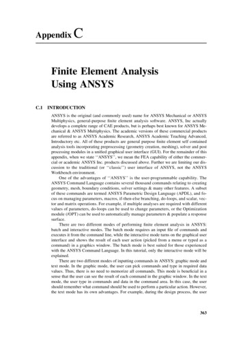
A frame is a structure composed of any number of frame-type members, joined atnodes, with axial and flexural stiffness continuity at the nodes.“Axx” is member cross-sectional area perpendicular to the local x-axis.“Izz” is member moment-of-inertia about the local z-axis.“E mod” is material modulus of elasticity.Section 3: Definitions Local and Global Coordinates: The FE spreadsheet is for 2D members in the x-y plane. Local coordinates are relative to the member; global coordinates are consistent forall members. There are as many local coordinate systems as there are members,but there is only one global coordinate system. Local x-axis is along the member axis, with positive being from the “i”-endtoward the “j”-end. Right hand rule applies such that if the x-axis points east and the y-axis north, thez-axis points up. Similarly, if the x-axis points east and the y-axis points up, thenthe z-axis points south.) Typically, lower case letters represent local coordinates, capital letters representglobal coordinates. In matrix notation, lower case letters indicate local memberproperties, with respect to local axis and upper case represent global properties.Section 4: Use of Spreadsheet for Simple Beam ExampleFigures 1A & 1B show a simple beam problem, including a sketch of the model, the inputloads and the resulting forces and deflections. To mirror the results: download the spreadsheet FE 5N 5M.xls (for Finite Element 5 Node 5 Member) save the original save a working copy as FE Sec4.xls change the input cells (colored yellow) to match Figure 1A verify that calculated results match Figure 1AThe structure model and input are annotated in Figure 1A. On this spreadsheet, thenumber of nodes is set at 5 and the number of members is set at 5. All nodes must beconnected and all members must be used. If a problem requires more nodes or moremembers a larger version of the spreadsheet is required. If a problem requires fewer than5 nodes or members this spreadsheet may be used, with the extraneous nodes andmembers inactivated. This is in contrast to typical commercial FE programs, in whichthe user selects the number of nodes and members.To inactivate a member, set properties Axx and Izz to near zero. In some cases thevalues can be set to zero, but in most cases setting properties to zero will result in aspreadsheet “!NUM” error message. To inactivate a node, connect to it only withinactivated members. The Figure 1 problem requires 5 nodes but only requires 4members so member 5 is inactivated by setting its properties to near zero.Calculated results are annotated in Figure 1B. Be careful of sign convention with respectto output. Coordinate axes are per right hand rule (per the Definitions section previously
and as shown in Fig 1B.), and results follow accordingly. Note also that consistent unitsmust be used.The Figure 1 Example has input of node-point loads of 2.0, 3.0 and 4.0 at nodes 2, 3 & 4respectively. The resulting maximum moment is 60 at member 3, end “i”, maximum ydirection deflection “Dy” is 0.95 at node 3.
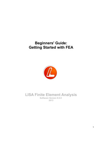
Section 5: Truss Example Figure 2.Figure 2 Example is a triangular truss, with a vertical 3.0 load and a horizontal 2.0 load,both at node 3.A truss is essentially a frame with no flexural resistance. Therefore, to analyze a truss themember moment of inertia needs to be set near zero (it cannot be set to zero or an Excelerror message “#NUM!” will result). To mirror Figure 2 results, copy the input from Fig.2 to your spreadsheet. Verify that your output matches Fig 2.Note that each node is at the end of at least one member (no nodes are unconnected). Tosee the effect of having an unconnected node, change member 5 i-node from “5” to “3”(by changing cell B21 from “5” to “3”) such that node 5 is not connected to anymembers. Output values all change to “!NUM” error message.Note that nodes 1, 4 & 5 can have the same coordinates (0,0), but that you can’t connect amember between two identical nodes because the member will have zero length. To seethe effect of a zero length member, change node 4 ordinates from (0,0) to (10,0) such thatit has the same coordinates as node 2. Output values all change to “#DIV/0!” errormessage.The result summary for the Figure 2 truss example is that node 3 has calculateddeflections of 0.003 vertical and 0.002 horizontal. The maximum member axial force is3.54 in member 3.
Section 6: Beam on Elastic Foundation with Uniform Member Load Figure 3The Figure 3 example is a beam on spring supports. Each support node has a k y springvalue of 80. The beam has varying uniform member loads per Figure 3. To mirrorresults, copy the input data to your working spreadsheet. Verify that your output matchesFig. 3. Note that Member Data, “Uni Load” input cells (G17-G21) are for inputting auniform load perpendicular to the local x-axis of the member (in the local y-direction).The input/output sections of the FE spreadsheet are divided into two categories: “NodeData” and “Member Data”. Nodes can have supports, applied forces, and deflections.Members have properties, end forces, and can have distributed load. Member end forcesare at node locations and are not necessarily maximum values for that member.Resulting deflections for this example vary from –1.0 to –1.8 and maximum moment is324 at member 2, end “j”. Note that maximums may be greater between nodes. If moredetail is required, use more nodes or further analyze critical members as a componentproblem.
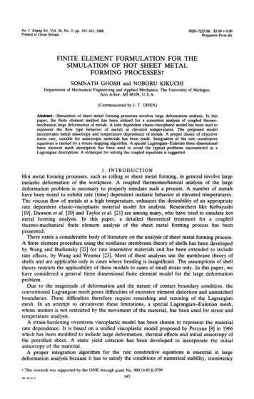
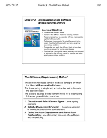
Section 7: 16-Node 37-Member Spreadsheet with Member End Release Fig 4 & 5Previous examples have been limited to a few nodes and a few members to demonstratethe functionality of the spreadsheet. Most design problems require more nodes andmembers. Figures 4 & 5 show a 16-node, 37-member spreadsheet, which is a functionalsize for a number of structural design problems. The particular problem shown is abuilding frame with two 1000 horizontal loads and some –50 uniform member loads.Maximum deflections are –1.7 in the y-direction and 9.9 in the x-direction. Reactions atnode 1 are FY –1500 & FX -637.2. Reactions are FY 4500 & FX -1362.8 atnode 14.Member end release of member-15 at node-15 is modeled by inserting a very shortmember-14 with a very low Izz value. Member-14 is essentially a pin of 0.001 diameterand very low friction in this example.
FIGURE 43-STORY BUILDING EXAMPLE16 NODE, 37 MEMBER SPREADSHEETRev:1/25/12This spreadsheet is provided for illustrative teaching purpose only, and is not intended for use in any specific project." Anyone making useof the information contained in this spreadsheet does so at his/her own risk and assumes any and all resulting liability arising therefrom.NODE DATA:Node 1620Support SpringsInput Forcesk rotk yk 9999993030[rad]Support ReactionsOutput DeflectionsFXMomFYFXRot [radians] 00-1362.8-0.23000.0-0.02000.0-0.06123MEMBER DATA:Output Member ForcesMem I nodej node AxxIzzE modUni 01059657115-9557637-15003340.2001059657110 -19113-152-5464450.2001059657110 -17596-152-5465560.2001059657110 -16079-152-5466670.20010596571-5010 0-211-211-211000000000000000000000
Section 8: Matrix Size LimitationsMicrosoft Excel does impose size limitations on matrix operations. The largest matrixthat could be inverted with Excel 2000 was 51x51. More recent versions of Excel haveexpanded that capability, probably by orders of magnitude, but by way of example, a51x51 stiffness matrix limits a problem 51 Degrees-Of-Freedom (DOF). The FEspreadsheet allows 3 DOF per node (deflection in x & y, rotation in z), thus would belimited to 17 nodes by the 51 DOF constraint in Excel 2000.The stiffness matrix is square with size equal to the number of DOF. The number ofnodes determines the number of DOF and thus the stiffness matrix size. The number ofmembers is not a factor.Section 9: Checking ResultsIt is a good idea to perform some basic checks on results. applied forces calculated reactions values are of the expected order of magnitude obvious known values (example: a symmetric problem should have symmetricresults, a pinned end should have no moment) inactive members have no significant force deflection of fixed supports approaches zeroIt is also a good idea to check critical results. The sum of member end forces at a node equals applied node load. The sum of member resulting forces equals applied uniform load, and sum ofmember moments equals zero.The member force check is particularly useful to verify the sign of reaction forces. It iseasy to get mixed up on which direction a member end shear force is acting.Be wary of thinking that a small number of nodes are just not enough for your problems.I have never seen a design that was flawed because the designer used too few nodes.Conversely, I have seen numerous designs that were flawed because the computer modelwas too large, too complex, and too difficult to visualize and check.This FE spreadsheet can be an effective tool for analysis, but is can be equally effectivein checking output from large complex problems, either by condensing the problem into asmall approximation that the spreadsheet can handle, or be analyzing parts from withinthe large problem.Section 10: Basic FE TheoryThis chapter gives a basic description of the solution method used in the FE spreadsheetwithout going into the details of the underlying theory. More detailed theory can befound from a multitude of sources should the user be so inclined to pursue.
Finite element method involves generating a series of compatibility equations relatingstructure deflections and forces. The equations are handled in matrix form for simplicityand easy of manipulation.The FE spreadsheet performs the following steps using Excel functions (without macrosor VBA programming): Calculates member local stiffnesses transforms local stiffness to global stiffness components, sums global stiffness components to formulate the global stiffness matrix inverts the global stiffness matrix multiplies the inverted stiffness matrix * node forces to calculate node deflections calculates member end forces from node deflectionsThe basic equation relating local member end-forces with end-deflections is:(6.1) f k * d (a Bold letter indicates a matrix)In expanded form:mz ivy ivx imz jvy jvx j4 EI / L6 EI / L 206 EI / L 2 12 EI / L 3000AE / L2 EI / L 6 EI / L 206 EI / L 2 12 EI / L 3000 AE / L2 EI / L 6 EI / L 204 EI / L6 EI / L 206 EI / L 2 12 EI / L 306 EI / L 2 12 EI / L 3000 AE / L00AE / Ldz idy idx idz jdy jdx jLower case matrix letters indicate local coordinates & UPPER CASE letters indicateglobal coordinates. The force vector f consists of mz, vy, and vx for ends “i” and “j”. The stiffness matrix k is the 6x6 matrix with variables E, I, L and A. The deflection vector d consists of dz, dy, and dx for ends “i” and “j”.Note that these are “local” matrices, with the x-axis being aligned with the axis of themember.In global coordinates, the stiffness equations become:(6.2) F K*D, where:n degrees-of-freedom (3*num-of-nodes for the FE Spreadsheet)F is a force vector,D is the resulting deflection vector,F & D are vectors with “n” number of elementsK is a square stiffness matrix, of size n*nIn a typical structure problem, the known values are: member properties (local) structure geometry (both local and global), and applied forces (global).
Knowing local member properties and geometry we can calculate the local stiffnessmatrix k for each member per Equation 6.1 above.Knowing the geometric relationship between local and global coordinates for eachmember allows use to transform each stiffness matrix from local to global coordinates.In the FE Spreadsheet, the local member axis defines the local x-axis, while the globalhorizontal axis is the X-axis. If the local x-axis is aligned identically with the global Xaxis, then local stiffness global stiffness. For all other cases, where the local memberaxis is not aligned with the global X-axis, local stiffness does not equal global stiffness.A coordinate transformation is required to calculate the relationship between local andglobal properties, with that transformation being a function of the angle between the “x”and “X” axes.In mathematical terms, first define a coordinate transformation matrix, t such that:(6.3) d t*DMember end forces can be similarly transformed by t such that:(6.4) f t*FRecalling (6.1), f k * d,Then substituting (6.3) and (6.4) into (6.1)t*F k*t*DThen, pre-multiply each side by t-inverse, or t-1.t-1*t*F t-1*k*t *DSimplifying with t-1*t unity matrix and defining k T t-1*k*t:(6.6) F k T * D where:(6.7) k T t-1*k*t a member stiffness matrix transformed to global coordinates.Once all member stiffness matrices are transformed to a global reference (ie: k T iscalculated for each member), global stiffness at each node can be calculated by summingthe global stiffness of each member that is connected to that node. For example, ifmembers 3, 4 & 5 connect at joint 10, and their X-force stiffnesses are 1, 2 & 3 kips/ftrespectively, the global stiffness factor for joint 10 would be the sum of the stiffnesses, or6 kips/ft. The stiffness of each node is calculated by summing the contributing stiffnesselements from each k T matrix, then all the node stiffness values are assembled to formthe global stiffness matrix, K.Note that if a node is a support point, there is an external or global support stiffness thatmust be added to the k T sum for that node. In the FE spreadsheet, all supports must beentered as support “springs”. As in real structures, there is no infinitely rigid support, butabsolute fixity can be approached by inserting very high support spring values.The known applied global forces are assembled into the force vector, F.Recalling equation (6.2), F K * D; we have now calculated F & K so D is the onlyunknown. To solve for D pre-multiply by K-1, where K-1 the inverse of K.K-1 * F K-1*K * D, but since K-1*K is the identify matrix, this simplifies to(6.2) K-1 * F D, where K-1 is calculated by an Excel matrix inversion function.
Inherent in the formulation of the stiffness equations is linear elastic theory, with all itsassumptions, particularly that stress and strain are related in a linear fashion, deflectionsare small and materials are isotropic and homogeneous. Also note that the elements ormembers in this spreadsheet are limited to axial and flexural strains, shear strains areassumed to be negligible and are not calculated.Section 11: Spreadsheet Layout / DesignFigure 6 shows local stiffness and transformation matrices (k & t) for each member ofthe 5-member Example 2.Figure 7 shows: Equation (6.7) result, k T, for each member. Index numbers to position k T elements into global stiffness matrix K. Applied load vectors Calculated displacements Calculated local member forces by substituting (6.3) into (6.5) f k*t*DFigure 8 shows: K, global stiffness matrix K -1, inverse of K F, global applied load vector D, calculated node displacement vector
Section 12: Linking spreadsheets for progressive analysisOne of the powerful features of spreadsheet FE analysis is the ability to link spreadsheetsto represent a series of consecutive loadings. A few examples of this application: A steel frame structure that has composite concrete – one spreadsheet couldanalyze the steel-only loads, a second spreadsheet could analyze loads on thecomposite section, a third spreadsheet could be a summation of the first two. Calculating deflections during a sequential
course. Finite element analysis has broad application and in different contexts terms may have different meanings, so this section defines terms as used in this course. The second portion of the course provides a number of FE analysis examples / applications for structural engineers. It is important to see applications and results before