Transcription
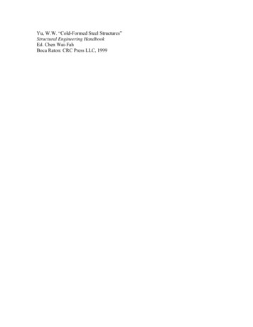
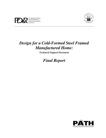
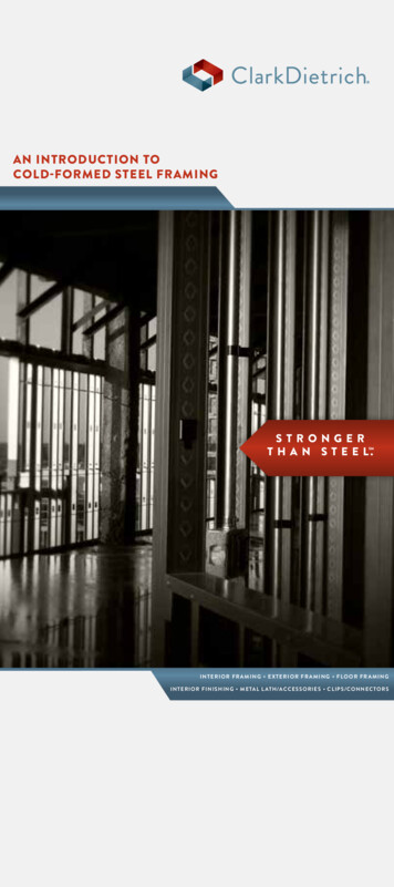
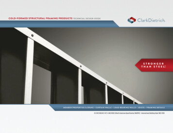
TECHNICAL NOTEtest 5.00 5.00On Cold-Formed Steel ConstructionCold-Formed Steel Engineers Institute Washington, DC www.cfsei.org 1-800-79-STEELSCREWS FOR COLD-FORMED STEEL-TO-WOOD ANDWOOD-TO-COLD-FORMED STEEL ATTACHMENTSThis Technical Note updates and replaces LGSEA Technical Note 565DSummary: Screws are often used to attach Cold-Formed Steel (CFS) framing to wood members or wood structural panel decking to CFS joists or rafters. The AISI North American Specification for the Design of Cold-FormedSteel Structural Members (AISI S100) provides design equations for screw connection capacity for CFS members. The National Design Specification for Wood Construction (NDS) provides design equations for fastener/connection capacity (nails, wood screws, bolts, etc.) in wood members. The Engineered Wood Association (APA)and the building codes offer several resources for determining the capacity of screw connections attaching woodsheathing. This Tech Note reviews these resources and discusses design and detailing of these fastener connections.Disclaimer: Designs cited herein are not intended to preclude the use of other materials, assemblies, structuresor designs when these other designs and materials demonstrate equivalent performance for the intended use;CFSEI documents are not intended to exclude the use and implementation of any other design or constructiontechnique.Pan head screws are most often used. Loose washersare not usually used unless required to increase pullover resistance of the attached steel sheet. The shaft iscovered with coarse threads along at least 2/3 of thescrew length. Standard wood screws are not typicallyfully threaded; in certain situations, fully threadedscrews may be used to maximize withdrawal capacityof the fasteners in wood. Standard wood screws havean unhardened gimlet point and are design to penetrate wood only. These screws are not intended topenetrate steel of any thickness.INTRODUCTIONCold-Formed Steel (CFS) framing is often used withwood products. Steel stud walls often support woodtrusses, wood I-joists or glued-laminated (glulam)beams. Screws are often used to connect these members. In addition, wood structural panels are used assheathing over CFS rafters, joists and wall studs.The capacity of self-drilling tapping screws in CFS-toCFS connections is referenced in the AISI S100 Specification and is relatively straightforward. The capacity ofscrews in wood is more complicated to determine dueto the many factors that affect screw connectionstrength. Also, particular attention must be paid to selecting a fastener that will penetrate steel and woodlayers and properly grip the members.Chapter 11 of the NDS provides guidelines and designequations for the use of standard wood screws. In order to use the NDS installation requirements, fastenersmust comply with ANSI/ASME Standard B18.6.1-1981.This standard dictates the head size, threads, diameter,and manufacturing tolerances for wood screws. Table 1shows pre-drilling requirements for wood screws. PreSCREWS FOR CFS-TO-WOODdrilling of the wood member is often required to preventsplitting of wood and to prevent fastener failure duringATTACHMENTSdriving. This pre-drilling is specified by the NDS forscrews loaded in withdrawal in wood species with aStandard Wood Screwsspecific gravity (G) of 0.50 or greater, and for woodscrews loaded laterally in all wood species. The NDSWhere steel connectors have pre-punched or prerequires that lead holes not exceed these values indrilled holes, standard wood screws (or nails) may beorder for design equations to be applicable. Pre-drillingused as shown in Figure 1. Figure 2 illustrates the gemay not be required for some proprietary screws.ometry of standard wood screws.Cold-Formed Steel Engineers Institute1TECH NOTE F101-12September 2012
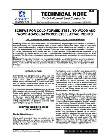
Figure 1: CFS-to-Wood Screw ApplicationsFigure 2: Screws for CFS-to-Wood AttachmentsTECH NOTE F101-12September 20122Cold-Formed Steel Engineers Institute
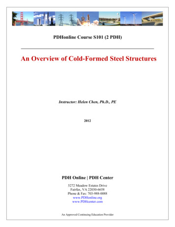
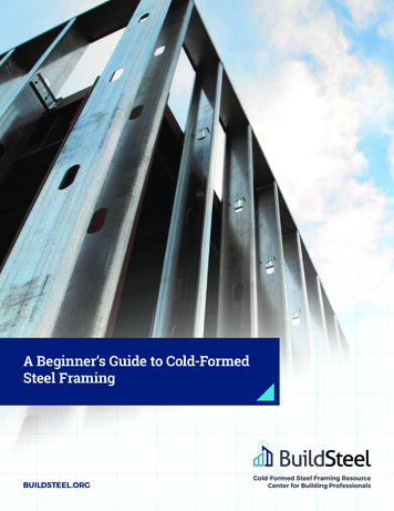
Table 1: Wood Screw Lead Hole Requirements (based on 11.1.5 of NDS 2012)ScrewNum ber(#)Nomi nal Di ameter,D (in.)RootDiame ter, 30.1310.1420.1520.1710.196Lead hole diameter forwithdrawal loading (in.)G 0.50.5 G 0.6G 1/81/81/81/83/16Lead hole diameter forlateral loading (in.)G 0.6G 0.6Sha Threa Sha :Wood screw shall be inserted into the lead hole using a screw driver or other tool, not by driving with a hammer.No reduction to design values is anticipated if soap or other lubricant is used on the screw or in the lead holes tofacilitate insertion and to prevent damage to the wood screw.G is the specific gravity of wood species group (See Table 11.3.3A of NDS).Nominal diameter (D) and root diameter (Dr) are taken from Table L3, Appendix L of NDS.Table 2 shows allowable withdrawal loads for screws inwood. A key factor in wood screw strength is the specific gravity of the wood member (G), which determinesthe withdrawal capacity. Design values are given forthree species groups commonly use in North America.Withdrawal is a function of wood strength, screw diameter and threaded penetration depth.Self-Piercing Tapping ScrewsSelf-piercing tapping screws used for wood connections may be used as shown in Figure 1, where unpunched cold-formed steel members 33 mils or lessmust be attached to wood members or for thicker steelmember where pre-punched steel connectors areTable 3 shoes allowable shear loads for screws in used .wood. These values also depend on specific gravity ofthe wood, which determines the dowelbearing Figure 2 illustrates the geometry of a self-piercing tapstrength of the wood. In addition, these values also ping screw. These screws have a self-piercing point asdepend upon the dowel strength of the attached steel defined in ASTM C-1513 (2010) are casehardened andsheet and the bending strength of the screw.capable of piercing steel sheet up to 33 mils thick.Based on a manufacturer’s recommendation, some selfThe values listed in Tables 2 and 3 apply to wood and/ -piercing screws can penetrate thicker steels. Hexor dowel bending-yielding failure only. Adjustment fac- washer heads are used because this head style hastors listed in Table 4 must be applied to determine the the best torque capacity in order to enable both penefinal allowable load for a connection. Screw connection tration of the un-punched steel sheet and penetration offailure in the steel sheet must also be checked. This the wood member without the benefit of a pilot hole.should include checks for bearing, pullover, edge dis- Commonly used sizes of self-piercing tapping screwstance and other factors as required. Wood adjust fac- are #8 and #10 diameter screws up to 3 in. long. Thesetors should not be applied to the strength of the screws screws have coarse threads designed to better grip theand the attached steel sheet when the capacity is de- wood members. Self-piercing tapping screws are typitermined per AISI S100.cally fully threaded for lengths 1-1/2 in. and less.Longer screws are typically threaded over 2/3 of theirProprietary connectors, such as the “hurricane ties” length. Loose washers are not usually used unless reshown in Figure 1 often have published tested capaci- quired to increase pull-over resistance of the attachedties for specific size screws or nails. If the use of other sheet. Steel backed, bonded neoprene washers arefasteners is desired, the designer should determine often used where watertight connections are desired.what impact the change may have on the allowableload of the connection.Cold-Formed Steel Engineers Institute3TECH NOTE F101-12September 2012
Table 2: Wood Screw Withdrawal Capacity (based on 11.2.2 of NDS 2012)Wood SpeciesCombinationScrewNumber(#)6NominalDiameter,D (in.)0.138WithdrawalCapacity,W 62140.24212181101121161182G 0.55(Southern Pine)G 0.50(Douglas Fir‐Larch)G 0.42(Spruce‐Pine‐Fir)Screw Length (in.)Notes:Withdrawal design value, W 2850 G2D (Equation 11.2‐2 of NDS).To determine the adjusted design value W’, multiply W by all applicable adjustment factors CD, CM and Ct (SeeTable 4(a)).Values are for screws inserted in side grain, with screw axis perpendicular to wood fibers. Values are not appro‐priate for end‐grain loading.Screws must comply with ANSI/ASME Standard B18.6.1‐1981.Assumes threaded length is 2/3 of total wood screw length.Steel sheet must also be checked for pull‐over resistance based on AISI S100 screw provisions.Tabulated values are for failure in the wood member.G is the specific gravity of wood species group (See Table 11.3.3A of NDS).TECH NOTE F101-12September 20124Cold-Formed Steel Engineers Institute
Table 3: Wood Screw Lateral Capacity (based on 11.3 of NDS 2012)Shear design Values, Z (pounds) Allowable LoadsWood Species Com binationG 0.55(Southern Pine)Fem 5526 psiFes 61875 psi(ASTM A1003, Grade33 steel)G 0.50(Douglas Fir‐Larch,Structural I Plywood,OSB‐All Grades)Fem 4637 psiFes 61875 psi(ASTM A1003, Grade33 steel)G 0.42(Spruce‐Pine‐Fir,Other PlywoodGrades)Fem 3364 psiFes 61875 psi(ASTM A1003, Grade33 steel)NominalDiameter,D (in.)Screw BendingYield Strength,Fyb (psi)Min. screwpenetra tion, Pmin(in.)0.138100,0000.164Sheet Steel Thickness ,0001.452132133134135140Notes:Lateral design value, Z, is based on the minimum computed yield mode value using equations in Tables 11.3.1A and11.3.1B of NDS.Minimum penetration of wood screw (Pmin) into the main member shall be 6D per Section 11.1.5.6 of NDS.Steel sheet must also be checked for shear resistance, using screw root diameter and AISI S100 Section E4. Valuesabove are for failure in the wood member and dowel bending yield only.To determine the adjusted design value Z’, multiply Z by all applicable adjustment factors – CD, CM, Ct and Ceq (SeeTable 4(a)).Screw bending yield strengths were taken from NDS Appendix I, Table 1. Presumed screw yield strength is based oncommonly available screws. Confirm with selected screw supplier.Screws must comply with ANSI/ASME Standard B18.6.1‐1981.Assumes threaded length is 2/3 of total wood screw length.G is specific gravity of wood species group (See Tables 11.3.3A and 11.3.3B of NDS).Cold-Formed Steel Engineers Institute5TECH NOTE F101-12September 2012
Table 4: Wood Screw Adjustment Factors (based on Table 10.3.1 of NDS 2012)4(a) Applicability of Adjustment Factors for Wood Screws (Table 10.3.1 of NDS)*LoadsWith W’ Wdrawal,Lateral,xZ’ Z xLoad Dura Wet ServiceTemperatureEnd Graintion FactorFactorFactorFactorCDCMCtN/ACDCMCtCeg*Other factors may apply; refer to NDS for Group Action Factor (Cg), Geometry Factor (CΔ) and DiaphragmFactor (Cdi).4(b) Load Duration Factors (Table 2.3.2 of NDS)*Load DurationPermanentTen YearsTwo MonthsSeven DaysTen MinutesCD0.91.01.151.251.6Typical Design LoadsDead LoadOccupancy Live LoadSnow LoadConstruction LoadWind/Earthquake Load4(c) Wet Service Factors for Wood Screws, CM (Table 10.3.3 of NDS)Moisture ContentLoadsAt Time of Fabrica tionIn ServiceCMWithdrawalAny 19%1.0(W)Any 19%0.7 19% 19%1.0 19% 19%0.4*Any 19%0.7Lateral (Z)*CM 0.7 for screws with diameter, D, less than 1/4 in. CM 1.0 for screw connections with : (1) one fastener only or(2) two or more fasteners placed in a single row parallel to grain or (3) fasteners placed in two or more rows parallel tograin with separate splice plates for each row. Note: Steel framing will require special corrosion protection for conditions that would warrant the use of wet service factors in wood designTECH NOTE F101-12September 20126Cold-Formed Steel Engineers Institute
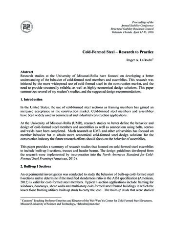
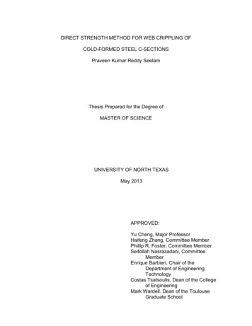
4(d) Temperature Factors for Wood Screws, Ct (Table 10.3.1 of NDS)*CtIn Service Mois ture Conditions*T 100 F100 F T 125 F125 F T 150 FDry1.00.80.7Wet1.00.70.5*Wet and Dry service conditions for screws are specified above in Table 4(c).4(e) End Grain Factor for Wood Screw, Ceq (Section 11.5.2 of NDS)Ceq 0.67, when the screws are inserted in the end grain of the main member, with the screw axis parallel to the woodfibers.There are no design provisions that specifically addressthe strength of self-piercing tapping screws. Many manufacturers supply tested design values for these fasteners;however this data is limited and does not address the numerous factors that the NDS accounts for in its woodscrew provisions. The NDS requires that wood screwscomply with ANSI/ASME Standard B18.6.1-1981 in order for its design provisions to apply. It should be notedthat most self-piercing tapping wood screws comply withANSI/ASME Standard B18.6.1-1981 in all ways exceptfor head style. This is because hex washer heads are noconsidered in the standard. If a particular self-piercingtapping wood screws complies with all other portions ofANSI/ASME Standard B18.6.1-1981 it would be reasonable for the design values in the NDS and tables 2, 3 and4 to be used, provided that the screw does not split thewood (or a pre-drilled hole must be provided per NDS toprevent splitting).SCREWS FOR WOOD-TO-CFSATTACHMENTSWood-to-CFS screw connections are used to attach woodpanels or members to steel framing members as shown byFigures 3 and 4. Heads have a countersunk design, tomount flush with the wood surface and are usually Phillips-drive type. Other available head types are trim-head,bugle-head, wafer-head and flat-head. Specialty countersunk head styles may include the flat or wafer style withcutting nibs under the head to create a counter-bore in thewood, which helps prevent wood splitting. All wood-toCFS screw fasteners should comply with ASTM C1513(2010), which governs the performance requirements ofsteel tapping screws.Figure 3: Wood-to-CFS Screw ApplicationsCold-Formed Steel Engineers Institute7TECH NOTE F101-12September 2012
Figure 4: Screws for Wood-to-CFSAttachmentCommon structural uses of wood-to-CFS screws areroof and floor diaphragms and shear walls. In theseapplications, the strength of the entire assembly mustbe determined by tests, and allowable loads are published in the model building codes. The APA publishesdiaphragm values for roof and floor assemblies in apublication titled “Wood Structural Panels over MetalFraming” (Form No. T625C, 2009). When the strengthof an individual fastener is required, the APA also publishes “Fastener Loads for Plywood-Screws” (Form No.E830E, 2011), which provides tested allowable shearand uplift values for plywood to steel connections.Alternatively, some decking screws feature small“wings” above the drill point on the pilot section of thescrew These wings prevent the deck from riding up theshaft by reaming out a hole that is slightly larger thanthe threaded diameter of the screw. The wings are intended to break off once they strike the steel sheet.The shaft of the self-drilling tapping screw for woodattachment has threads suitable for tapping and gripping the steel member. Fine threads are typically usedfor steel sheet 68 mils and thicker, while coarsethreads should be used for thinner sheets. Based onAISI S200, proper installation requires a minimum ofthree threads must be exposed beyond the thickness ofthe member.Self-Drilling Tapping ScrewsWhen attaching wood to 43 mils or thicker steel, selfdrilling tapping screws may be required. These screwsmust comply with SAE J78 (1998), which specifies thedimensions and performance of self-drilling screws.Self-drilling screws have a specific “drill capacity”,which is the total thickness of steel they are capable ofdrilling through. The drill capacity is a function of bothscrew size and point style. Drill capacity for screws istabulated in both the SAE J78 standard, and in CFSEITech Note F102 (2011), Table 1. Most self-drilling tapping screws for wood attachment use number 2, 3 or 4point style. (The larger the number, the larger the drillcapacity of the screw). During driving, the screw quicklydrills throughthe decking but remains on the surface of the CFSframing member, while the driller tip penetrates thesteel sheet. To prevent the decking from riding up thescrew shaft, the tip of the screw and the pilot sectionmust be longer than the depth of the decking, as shownin Figure 4.TECH NOTE F101-12September 2012Self-Piercing Tapping ScrewsWhen attaching wood decking to 33 mils or thinnersteel, self-piercing tapping screws may be used. Thistype of fastener pierces the wood and steel in one continuous motion. These screws are defined in ASTM C1513 (2010) and comply with ASI/ASME B18.6.3(2010), which governs the manufacture of threadforming tapping screws. Self-piercing tapping screwsfor wood attachment are casehardened and have apiercing tip which enables them to penetrate the steelsheet. Self-piercing tapping screws for wood attachment have coarse threads suitable for tapping and gripping the steel sheet, and should be long enough so thata minimum of three threads are exposed after installation.8Cold-Formed Steel Engineers Institute
References1.2.3.4.5.6.7.8.9.AISI S100. (2007/S2-10). North American Specification for the Design of Cold-Formed Steel Structural Members with Supplement 2 (2010). American Iron and Steel Institute, Washington, D.C.ANSI/ASME B18.6.1-1981. (Re-affirmed 1997). Wood Crews (Inch Series). New York, NY: ASME International.ANSI/ASME B18.6.3 (2010). Machine Screws, Tapping Screws, and Metallic Drive Screws (Inch Series). NewYork, NY: ASME International.ASTM C1513. (2010). Standard Specification for Steel Tapping Screws for Cold-Formed Steel Framing Connections. West Conshohocken, PA: ASTM International.CFSEI Tech Note F102. (2011). Screw Fastener Selection For Cold-Formed Steel Frame Construction.Washington, D.C.: Cold-Formed Steel Engineer’s Institute.Form No. E830E. (2011). Fastener Loads for Plywood - Screws. Tacoma, WA: APA - The Engineered WoodAssociation.Form No. T625C. (2009). Wood Structural Panels Over Metal Framing. Tacoma, ,WA: APA - The EngineeredWood Association.NDS. (2012). National Design Specification for Wood Construction. American Wood Council.SAE J78. (1998). Steel Self-Drilling Tapping Screws. Warrendale, PA: SAE International.Primary authors of original Tech Note:John Lyons, Structural Evolution, LLCTechnical Review and updating for Revised Edition:Tamil Samiappan, ITW Building Components Group, Inc.Nathan Blong, Uzun & CaseRoger LaBoube, Center for Cold-Formed Steel StructuresMaribeth Rizzuto, CFSEIThis “Technical Note on Cold-Formed Steel Construction” is published by the Cold-Formed Steel Engineers Institute (“CFSEI”). Theinformation provided in this publication shall not constitute any representation or warranty, express or implied, on the part of CFSEI orany individual that the information is suitable for any general or specific purpose, and should not be used without consulting with aqualified engineer, architect, or building designer. ANY INDIVIDUAL OR ENTITY MAKING USE OF THE INFORMATION PROVIDEDIN THIS PUBLICATION ASSUMES ALL RISKS AND LIABILITIES ARISING OR RESULTING FROM SUCH USE. CFSEI believesthat the information contained within this publication is in conformance with prevailing engineering standards of practice. However, noneof the information provided in this publication is intended to represent any official position of the CFSEI or to exclude the use and implementation of any other design or construction technique.Copyright 2012, Cold-Formed Steel Engineers Institute Washington, DC www.cfsei.org 1-800-79-STEELCold-Formed Steel Engineers Institute9TECH NOTE F101-12September 2012
Cold-Formed Steel Engineers Institute 1 TECH NOTE F101-12 September 2012 test 5.00 This Technical Note updates and replaces LGSEA Technical Note 565D Summary: Screws are often used to attach Cold-Formed Steel (CFS) framing to wood members or wood struc- tural panel decking to CFS joists or rafters.