Transcription
WE GO WHERE OTHERS WILL NOTFlexible CircuitandHeaterDESIGN GUIDEISO 9001:2008, ISO 14001:2004, ISO 13485, TS 16949,ROHS COMPLIANT, ITAR REGISTERED, UL REGISTERED,FDA REGISTERED, IPC MEMBER, BBB MEMBER
WE GO WHERE OTHERS WILL NOTApplication DocumentsTABLE OF CONTENTSForward.1Why Use Flex.1Terms and Definitions. 2-3IPC-2152 Standard for Determining Current -Carrying Capacity inPrinted Board Design.IPC-2221 Generic Standard on Printed Board DesignFlex Circuit Classes / Types. 4-5IPC-2223 Sectional Design Standard for Flexible Printed BoardsFlex Circuit Mechanical Design Steps.6IPC-6011 Generic Performance Standard for Printed BoardsStandard Materials.7IPC-6013 Qualification and Performance Specification for FlexiblePrinted BoardsTerminations.7Cost Drivers.8Flex Circuit Design Guidelines.9, 12-13Conductor Width Nomograph. 10-11Handling /Assembly Guidelines.14Circuit Forming Guidelines.15FCT Capabilities. 16-17High Density Interconnect (HDI).18IPC-4101 Specification for Base Materials for Rigid and MultilayerPrinted BoardsIPC-4202 Flexible Base Dielectrics for Use inFlexible Printed CircuitryIPC-4203 Adhesive Coated Dielectric Films for Use as Cover Sheetsfor Flexible Printed Circuitry and Flexible Adhesive Bonding FilmsIPC-4204 Flexible Metal-Clad Dielectrics for Use in Fabrication ofFlexible Printed CircuitryRigid Flex Design Guidelines.18IPC-SM-840 Qualification and Performance Specification ofPermanent Solder MaskRequirements for Flex Quote / Fabrication. 19*For more information on IPC specifications, contact IPCShipping Options.193000 Lakeside Drive, Suite 309SBannockburn, IL 60015-1249 USATel: 847.615.7100/FAX:847.615.7105www.IPC.orgFlexible Heaters. 20-21Flexible Circuit Technologies (FCT)9850 51st Ave N. Plymouth, MN 55442763-545-3333 (main) 888 -921-6167 (toll free)www.flexiblecircuit.com sales@flexiblecircuit.com
FORWARDFlexible circuit designs share many of the same challenges as rigid PCB designs, but there arealso many differences and additional challenges. The very nature of a flex circuit being able tobend and flex make it as much a mechanical device as an electrical one. This creates a specialset of requirements unique to flexible circuitry. Understanding how these requirements interactwill allow the PCB designer to create a flex circuit that balances the electrical and mechanicalfeatures into a reliable, cost effective interconnect solution. We hope you find this flex circuitdesign guide a useful tool throughout your design process. We also encourage you to call oneof our knowledgeable, experienced Applications Engineers at any time during your designprocess. They stand ready to assist you at every step to ensure that your flex circuit design isa successful one.WHY USE FLEX?There are many reasons to use flexible circuitry as your interconnect choice. Amongthese are: Low Mass—Flexible circuits are onlya fraction of the mass of discreet wiringmaking them ideal for high shock, highvibration applications. No Wiring Errors—Since the conductorson a flex circuit are photo-defined just likea rigid a PCB, there will never be a wiringerror. High Wiring Density—Because theconductors in a flexible circuit are photodefined like a rigid PCB, flexible circuitsare capable of very small conductors andtherefore ultra-high wiring density. Theycan take up to 75% less space than a similar wiring harness. The Ability to Bend and Flex—Perhapsthe single biggest reason for using flexiblecircuits is their ability to bend and flex tofit unique applications. Ease of Assembly—Every flex circuit iscustom to its application, and if designedproperly, should fit perfectly and consistently. Termination Options—Flexible circuitscan accept PCB connectors, FFC connectors,and insulation displacement connectors.Plus, several options such as unsupportedfingers than can only be done on flex.1 Lowest Total Cost of Ownership—Using flexible circuitry as your interconnect solution gives your designers thefreedom to eliminate costly features suchas board to board connectors and jumperwires while streamlining assembly timewhich results in the lowest TCO.
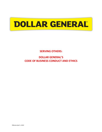
TERMS AND DEFINITIONSAccess Hole: Opening in cover material toallow electrical connection to a conductor.Access HoleBondply: A combination of insulating material with adhesive on both sides suppliedas a film.Circuit Class: Classes 1-3 based on inspection, testing, and performance requirements.Circuit Type: Types 1-5 based on layercount, material selection, and vias.ACF: (Anisotropic Conductive Film) Adhesive films used to electrically and mechanically join conductive surfaces on a flex circuit.These films are available in both thermal setting and pressure sensitive versions and areonly electrically conductive in the Z-axis.Conductive Ink: Conductive particles, usually silver or copper, suspended in an adhesive carrier, usually epoxy. Can be used tomake conductive traces, or as a replacementfor a copper shield. Typically more flexiblethan copper foil.Cover: The insulating material covering theouter layers of a flexible circuit.Covercoat: A liquid or semi-liquid insulating material used as a permanent cover overthe outer conductive layers.Coverlay: A combination of insulating material with adhesive on one side supplied asa film.ENIG: Electroless Nickel Immersion Gold.ENEPIG: Electroless Nickel Electroless Palladium Immersion Gold.Epoxy Adhesive: Thermo-setting film adhesive. The preferred adhesive for flex circuits manufactured in Asia. See also AcrylicAdhesive.Fillets: A flaring of a conductor as it connects to a pad. Used to minimize stress.Membrane switch using printedconductive silver ink.ACF Bonding for flip chip assembly.Acrylic Adhesive: Thermo-setting filmadhesive. The preferred adhesive for flex circuits manufactured in the US. See also EpoxyAdhesive.Conductor: The path that carries electricalcurrent from one point to another.Conductor Spacing: The width of spacebetween conductor strands. A certain minimum conductor spacing must exist in order toprevent conductors from shorting together.Adhesive Squeeze Out: Adhesive thatflows out on to a conductive surface duringlamination.Annular Ring:The ring of exposed copperor solder thatsurrounds a flexcircuit’s larRingBase Material: Copper clad flexibledielectrics, usually polyimide film, with orwithout adhesive.Bend Ratio: The ratio of bend radius tocircuit thickness.Conductor Width: The width of a conductor measured across its base.ConductorWidthFR4: Common epoxy based hardboard material used to make stiffeners (no copper cladding), or base material in a rigid flex circuit(copper clad).Gerber: The most common PCB electronic data exchange format. This formatis preferred over the other formats such asODB , and DXF.Hardboard: Resin impregnated glass cloth,most commonly epoxy or polyimide resin,with or without copper cladding.HASL: Hot Air Solder Level.Hold Down Tabs: An extension of copperon a conductor pad that aids the pad in gripping to the base substrate. Hold down tabsare also referred to as “anchoring spurs”.AdhesivePolyimideControlled Impedance: Combining material selection, circuit construction, and circuitfeature sizes to yield a predetermined characteristic impedance. Impedance control requirements typically result in a thicker, lessflexible circuit.2Hold-DownTab
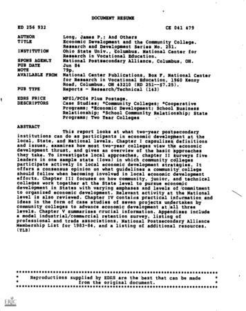
TERMS AND DEFINITIONSI-Beam Effect: Stacking conductors on topof each other on multiple layers, resulting ina thicker and stiffer circuit. Generally considered poor design practice and should beavoided.POP: Pads Only Plating. Refers to a processwhere copper is plated only in throughholes and on pads. Used to reduce thicknessand increase flexibility. Also referred to asselective or button plating.Polyester: Low temp, low cost insulatingmaterial.Major Access Hole: An access hole that islarge enough to expose a major portion of aconductor pad, which is usually plated witha final finish or coated with solder.Stiffener: A rigid sheet material, usuallyEpoxy/glass construction or thick polyimidefilm (.005"), used to rigidize areas of the flexcircuit that should not flex.Plated through holes connect circuit layers and areused for through hole component assembly.Polyimide: High temp insulating materialavailable in film, hard board, or B-stageadhesive. Polyimide film is the most commoninsulating material used in flex circuitry.Prepreg: Uncured resin impregnated glasscloth used as an adhesive in rigid flexcircuits. Resin can be any of a number oftypes including epoxy, polyimide, BT, etc.Stiffener applied to rigidize the area ofcomponent assembly.PSA: Pressure Sensitive Adhesive.Major Access Hole4. PolyimideMinorAccesscoversHole: areAn laminatedaccess hole thatoveretchedcopperexposes only a very small portion of a conductor pad, used on holes where a solderpad is not needed or desired. The cover holemust still be larger than the through hole toallow for normal registration tolerances.MinorAccess HolePTH: Plated Through Hole.Punch and Die: A very expensive steel toolused for punching covers, adhesives, andfinal circuit outlines that is capable of tens ofthousands of punches between sharpenings.Also capable of extreme accuracy.Rigid Flex: A circuit containing rigid PCBboards connected by integral flexible areaswhere the flexible materials and circuitry runthrough both rigid and flex areas.Silkscreen: A processs for applying legend,marking, LPI solder mask, and silver inkconductors.Neutral Bend Axis: Imaginary planarregion of flex that does not experience anytension or compression forces when thecircuit is bent or folded.Pad: A conductive land, usually round,and placed over holes drilled for electricalconnection.PIC: Photo Imageable Cover (cover coat).PadStrain Relief: Usually refers to a bead ofsemi-rigid adhesive applied along a rigid/flex interface, but can also refer to any ofa number of features that can reduce, oreliminate, stress concentration features.SMOBC: Solder Mask Over Bare Copper.SRD: Steel Rule Die, an inexpensive toolused to punch covers, adhesives, final circuitoutlines, etc. Constructed from a long bladethat is formed to a desired shape and thenpressed into a laser cut plywood base.Capable of hundreds or a few thousandpunches. Capable of moderate accuracy.3Silkscreen nomenclature can be useful to addidentifying markings to circuits.Termination: The method used to bringelectrical signals to/from the flexible circuit.Most commonly connectors, pins, or accessholes.Via: A plated through hole used to interconnect multiple layers of circuitry.
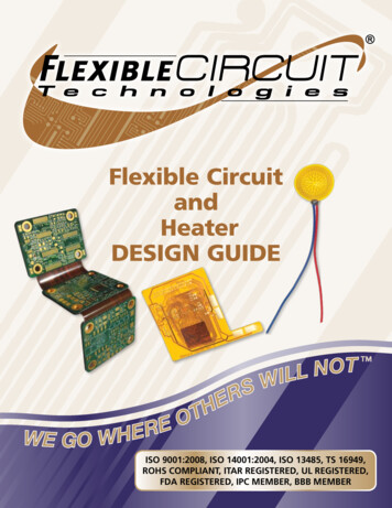
FLEX CIRCUIT CLASSES / TYPESCircuit Classes:IPC 6013 Type 1Flex circuits fall into 3 classes (1-3 per IPC-6013) based on the level ofinspection and testing required, and also by the performance requirements of the finished product. Single conductive layer Insulating material one or both sides Access to conductors on one or both sides Class 1 circuits have the minimum inspection, testing and performance requirements. These circuits are the least expensive and aretypically used in applications such as disposable electronics (e.g.musical greeting cards) and RFID tags.Access HolePolyimide CoverAdhesive Class 2 circuits have moderate inspection, testing, and performancerequirements. Class 2 circuits are more expensive than class 1 andare typically found in applications such as cameras, medical diagnostic equipment, and cell phones.Polyimide SubstrateCopper Pad Class 3 circuits have the highest level of inspection, testing andperformance requirements. Class 3 circuits are the most expensiveof the 3 classes, and are typically found in applications that involvethe taking or maintaining of life. Applications would include implantable cardiac devices and military/aerospace electronics.IPC-6013 Type 2Circuit Types: Two conductive layers with flexible insulating film between themFlex circuit type is determined by the number of conductive layers,construction/materials, and the presence or absence of plated throughholes. The common flex circuit types (1-4) are illustrated at right. Afifth flex circuit type (type 5) is very uncommon and is not shown. Type5 circuits are two or more layers without plated through holes. Plated interconnect holes Insulating cover material on one or both sides Access to conductors one or both sidesAccess HolePolyimide CoverAdhesiveCopper PadPolyimide CoverCopper-PlatedThrough HolePolyimide Substrate4
FLEX CIRCUIT CLASSES / TYPESIPC 6013 Type 3Type 1-Single Layer FlexDual access is accomplished on a single sided flex bylaser skiving openings on the bottom side of the flex. Three or more conductive layers Flexible insulating material between layers Plated interconnect holes Insulating cover material one or both sides Access to conductors one or both sidesAccess HoleCoverCopper PadPolyimide SubstrateBond PlyPolyimide SubstrateAdhesiveCoverCopper-Plated Through HoleIPC 6013 Type 4Type 4-Rigid FlexRigid flex circuits combine rigid FR-4 areas for dense component population interconnected with flexible polyimide areas which can be bent to accommodate overallpackaging needs. Two or more conductive layers Insulating material may be rigid or flexible Plated interconnect holes through flexand rigid materials Access to conductors one or both sidesthrough cover material or SMOBCPolyimide CoverAdhesivePolyimide CoverAdhesivePolyimide SubstrateCopper PadRigid MaterialCopper-Plated Through Hole5
FLEX CIRCUIT MECHANICAL DESIGN STEPSReview electrical schematic/net list toestimate approximate layer count. Accountfor all signal and plane layers. Also, referto the Conductor Width Nomograph (page11) for any conductors with high currentrequirements. Multiply the number of layersby .0055" to get the approximate overallthickness of the circuit (if your circuit hascontrolled impedance requirements, thismultiplier may be larger).Review mechanical requirements/solidmodel to determine minimum bend radii.Determine and evaluate bend ratio.Determine flex termination method(s).Create a “paper doll” of the proposed flexcircuit outline. The first paper doll outlinecan be created with just a ruler and a pencil,but subsequent iterations should then betransferred to a CAD program so that youcan keep track of your modifications. Placethe paper doll in the assembly to checkform and fit. Don’t forget to account for thetermination hardware. Make modificationsas required to optimize fit.Keep the assembler in mind during thefit check. If the paper doll tears duringinstallation, it may signal possible assemblyproblems. A flex circuit that is difficult to installwill add time (cost) to the assembly, and canbe a reliability risk due to possible damageto the circuit during the installation.Objective: Provide low profile interconnect for3 small PCBsBEFOREAFTERStep 1: Layoutcircuit footprint onCAD and create apaper doll.Step 3: Createpolyester mock-up.Step 2: Checkpaper doll for fit.Step 4: Checkpolyester mock-upfor form and fit.Step 5: Contact flex vendor to makemechanical mock up. This mock upshould accurately reflect the actualmaterials of the final circuit.Final step: Flex circuitRe-create the paper doll using .010"polyester sheet material. You can usuallyuse a standard copy machine to print thecircuit outline. Cut the model out and checkfor form and fit and modify as necessary. Thepolyester is a bit stiffer than paper and willbetter represent the mechanical propertiesof the flex circuit.Obtain a mechanical sample from yourflex circuit vendor. This sample will beconstructed from the same materials asthe final flex, but will not have any etchedcircuitry (only solid copper). All componentholes and circuit outline features should berepresented. Connectors can be glued inplace with epoxy to give a true sense of thefinal fit. This will be the final opportunity totweak your design prior to ordering actualcircuits. If you have followed the steps above,6the mechanical sample should require few, ifany, modifications.
STANDARD MATERIALSFlexible Circuit Technologies can work witha wide variety of flex circuit materials togive you the electrical and mechanical performance you require. However, to get thelowest possible cost for your flexible circuit,it is advisable to design your circuit usingstandard materials whenever possible. Usinguncommon materials in your design can addsignificantly to both the cost and the leadtime of your circuit.Insulating Material:Stiffener Material: Polyimide Film .001", .002", .003" Glass Reinforced FR4 (epoxy) Polyester Film Polyimide Film (non-reinforced) .005" PENFinal Finishes: PET ENIG Solder Mask ENEPIG PICConductive Material: Copper Foil ¼ oz (9 um), 1/3 oz., ½ oz.,1 oz., 2 oz. Hard Nickel/GoldAdhesive: HASL Epoxy .001", .002" Immersion Tin Constantan Modified Acrylic .001", .002" Tin Plate Cupro-nickel Prepreg Organic (OSP) Inconel PSA Silver Filled Epoxy Adhesiveless Carbon AluminumTERMINATIONSVirtually any connector or component thatcan be mounted on a rigid PCB can also bemounted on a flex circuit. In addition, flexcircuitry offers many other options includingunsupported fingers and insulation displacement connectors. Contact your FCT Applications Engineer to discuss which terminationoption will work best for your application.Circular ConnectorSMT ConnectorInsulation Displacement ConnectorsZIF Connector TerminalRight Angle ConnectorCard Edge ConnectorsCrimp Pins7
COST DRIVERSEvery designer is looking for ways to decrease costs without sacrificing performance. IPC research has shown that PCB designers driveover 75% of the circuit cost based on the decisions they make. It isimperative that the flex designer understand what features add valueand what features add only cost. Designers should never sacrifice reliability to save costs, but at the same time, many flex circuits are overspecified resulting in additional costs that add no additional value.Here is a list of the features that drive the majority of your circuitcost: Circuit Type (i.e. type 3 vs type 4)—Rigid flex circuits aretypically more expensive than multilayer flex with stiffeners.Scrutinize your design to determine if your application requires arigid flex construction, or if a multilayer with stiffeners will work. Ifin doubt, call your flexible circuit manufacturer and ask. Layer Count—As the number of layers increase, so does thecost. More layers will require additional materials and processingtime. Processing high layer count flex or rigid flex can also be verytechnically challenging which may result in reduced yields. Drawings Overly or Too Tightly Dimensioned—It isimportant to remember that you are purchasing a flexible circuit,not a machined part. The materials used to manufacture flexiblecircuits both permit and require looser tolerances than rigid PCBs.Each dimension placed on a drawing will have to be verified, soask yourself, “is this dimension adding value, or just cost?”. Allnon-critical dimensions on your flex circuit drawing should bedesignated as reference. Circuit Class (i.e. class 3 vs class 2)—Class 3 circuits requireadditional testing, inspection, and construction requirements whichmake them more expensive. Review the requirements of yourapplication to determine the proper class for your flex circuit. Circuit Size and Shape—Most flexible circuits are constructedin panel form. The greater the panel area a circuit occupies, thegreater the cost. There are instances where eve
The very nature of a flex circuit being able to bend and flex make it as much a mechanical device as an electrical one. This creates a special set of requirements unique to flexible circuitry. Understanding how these requir