Transcription
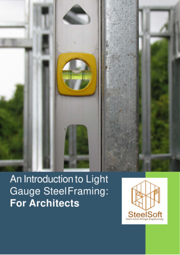
Expanding Your SolutionsSure-Span Light Gauge Steel Floor Joist SystemProduct Guide 2019Effective 05/16/2019
Table of ContentsIntroductionSure-Span Steel Floor Joist System . . . . . . . . . . . . . . . . . . . . . . . . . . . . . . . . . . . . . . . . . . . . . . . . . . . . . . . . . . . . . . . . . . . . . . . . . . . . . . . . . . . . . . . . . . . . . . . . . . . . . . . . . . . . . . . . . . . . . . . . . . . . . . . . . . . . . . . . . . . . . . . . . . . . . . . 1OverviewProduct Information for SSCJ (Joists) and SSRT (Rim Track) . . . . . . . . . . . . . . . . . . . . . . . . . . . . . . . . . . . . . . . . . . . . . . . . . . . . . . . . . . . . . . . . . . . . . . . . . . . . . . . . . . . . . . . . . . . . . . . . . . . . . . . . . . . . . . . . . . . . . . . . . . . . . . . . .Steel Thickness/Punch-Out Dimensions . . . . . . . . . . . . . . . . . . . . . . . . . . . . . . . . . . . . . . . . . . . . . . . . . . . . . . . . . . . . . . . . . . . . . . . . . . . . . . . . . . . . . . . . . . . . . . . . . . . . . . . . . . . . . . . . . . . . . . . . . . . . . . . . . . . . . . . . . . . . . . . . . . .Flange Joist Bridging . . . . . . . . . . . . . . . . . . . . . . . . . . . . . . . . . . . . . . . . . . . . . . . . . . . . . . . . . . . . . . . . . . . . . . . . . . . . . . . . . . . . . . . . . . . . . . . . . . . . . . . . . . . . . . . . . . . . . . . . . . . . . . . . . . . . . . . . . . . . . . . . . . . . . . . . . . . . . . . . . . . . . .Definitions of Structural Properties Notations . . . . . . . . . . . . . . . . . . . . . . . . . . . . . . . . . . . . . . . . . . . . . . . . . . . . . . . . . . . . . . . . . . . . . . . . . . . . . . . . . . . . . . . . . . . . . . . . . . . . . . . . . . . . . . . . . . . . . . . . . . . . . . . . . . . . . . . . . . . . . .2345TablesSure-Span Joist Structural Properties and Load Capacities: 7.25” to 14” Web . . . . . . . . . . . . . . . . . . . . . . . . . . . . . . . . . . . . . . . . . . . . . . . . . . . . . . . . . . . . . . . . . . . . . . . . . . . . . . . . . . . . . . . . . . . . . . . . . . . . . . . . . . . . . . 6Sure-Span Rim Track Structural Properties and Load Capacities . . . . . . . . . . . . . . . . . . . . . . . . . . . . . . . . . . . . . . . . . . . . . . . . . . . . . . . . . . . . . . . . . . . . . . . . . . . . . . . . . . . . . . . . . . . . . . . . . . . . . . . . . . . . . . . . . . . . . . . . . . 7Joist Span 10” Minimum Hole Offset From Bearing Support . . . . . . . . . . . . . . . . . . . . . . . . . . . . . . . . . . . . . . . . . . . . . . . . . . . . . . . . . . . . . . . . . . . . . . . . . . . . . . . . . . . . . . . . . . . . . . . . . . . . . . . . . . . . . . . . . . . . . . . . . . . 8–16Sure-Span Joists Allowable Web Crippling Capacities . . . . . . . . . . . . . . . . . . . . . . . . . . . . . . . . . . . . . . . . . . . . . . . . . . . . . . . . . . . . . . . . . . . . . . . . . . . . . . . . . . . . . . . . . . . . . . . . . . . . . . . . . . . . . . . . . . . . . . . . . . . . . . . . . . . 17Sure-Span Detail Number and Detail Description . . . . . . . . . . . . . . . . . . . . . . . . . . . . . . . . . . . . . . . . . . . . . . . . . . . . . . . . . . . . . . . . . . . . . . . . . . . . . . . . . . . . . . . . . . . . . . . . . . . . . . . . . . . . . . . . . . . . . . . . . . . . . . . . . . . . . . . . 18Systems1: Joist Connection Joist Bearing on Exterior Stud Wall . . . . . . . . . . . . . . . . . . . . . . . . . . . . . . . . . . . . . . . . . . . . . . . . . . . . . . . . . . . . . . . . . . . . . . . . . . . . . . . . . . . . . . . . . . . . . . . . . . . . . . . . . . . . . . . . . . . . . . . . . . . . . . . . . . . 191A: Joist Connection Joist Parallel to Exterior Stud Wall . . . . . . . . . . . . . . . . . . . . . . . . . . . . . . . . . . . . . . . . . . . . . . . . . . . . . . . . . . . . . . . . . . . . . . . . . . . . . . . . . . . . . . . . . . . . . . . . . . . . . . . . . . . . . . . . . . . . . . . . . . . . . . . . . . 201B: Joist Connection Joist Parallel to Exterior Stud Wall with Sure-Span Blocking . . . . . . . . . . . . . . . . . . . . . . . . . . . . . . . . . . . . . . . . . . . . . . . . . . . . . . . . . . . . . . . . . . . . . . . . . . . . . . . . . . . . . . . . . . . . . . . . . . . . . . . . . . 212: Joist Connection Joist Bearing on Exterior Concrete/Masonry/Insulated Concrete Forms (ICF) Wall . . . . . . . . . . . . . . . . . . . . . . . . . . . . . . . . . . . . . . . . . . . . . . . . . . . . . . . . . . . . . . . . . . . . . . . . . . . . . . . . . . . . . 223: Joist Connection Joist Bearing on Steel Structural End Member . . . . . . . . . . . . . . . . . . . . . . . . . . . . . . . . . . . . . . . . . . . . . . . . . . . . . . . . . . . . . . . . . . . . . . . . . . . . . . . . . . . . . . . . . . . . . . . . . . . . . . . . . . . . . . . . . . . . . . . 234: Joist Connection One Continuous Joist Bearing Over Stud Wall . . . . . . . . . . . . . . . . . . . . . . . . . . . . . . . . . . . . . . . . . . . . . . . . . . . . . . . . . . . . . . . . . . . . . . . . . . . . . . . . . . . . . . . . . . . . . . . . . . . . . . . . . . . . . . . . . . . . . . . . 245: Joist Connection One Continuous Joist Bearing on Steel Structural Member . . . . . . . . . . . . . . . . . . . . . . . . . . . . . . . . . . . . . . . . . . . . . . . . . . . . . . . . . . . . . . . . . . . . . . . . . . . . . . . . . . . . . . . . . . . . . . . . . . . . . . . . . . . 256: Joist Connection Non-Continuous Joist or Two Joists Bearing Over Stud Wall . . . . . . . . . . . . . . . . . . . . . . . . . . . . . . . . . . . . . . . . . . . . . . . . . . . . . . . . . . . . . . . . . . . . . . . . . . . . . . . . . . . . . . . . . . . . . . . . . . . . . . . . . . 267: Joist Connection Non-Continuous Joist or Two Joists Bearing on Concrete/Masonry/ICF Wall . . . . . . . . . . . . . . . . . . . . . . . . . . . . . . . . . . . . . . . . . . . . . . . . . . . . . . . . . . . . . . . . . . . . . . . . . . . . . . . . . . . . . . . . . . 278: Joist Connection Joist Bearing and Cantilevered Over Exterior Stud Wall . . . . . . . . . . . . . . . . . . . . . . . . . . . . . . . . . . . . . . . . . . . . . . . . . . . . . . . . . . . . . . . . . . . . . . . . . . . . . . . . . . . . . . . . . . . . . . . . . . . . . . . . . . . . . . . 289: Joist Connection Joist Bearing and Cantilevered Over Steel Structural Member . . . . . . . . . . . . . . . . . . . . . . . . . . . . . . . . . . . . . . . . . . . . . . . . . . . . . . . . . . . . . . . . . . . . . . . . . . . . . . . . . . . . . . . . . . . . . . . . . . . . . . . . 2910: Joist Connection Joist Bearing and Cantilevered Over Concrete/Masonry/ICF Wall . . . . . . . . . . . . . . . . . . . . . . . . . . . . . . . . . . . . . . . . . . . . . . . . . . . . . . . . . . . . . . . . . . . . . . . . . . . . . . . . . . . . . . . . . . . . . . . . . . . . 3011: Joist Connection Joist Bearing on Steel Ledger Member Attached to Concrete/Masonry Wall . . . . . . . . . . . . . . . . . . . . . . . . . . . . . . . . . . . . . . . . . . . . . . . . . . . . . . . . . . . . . . . . . . . . . . . . . . . . . . . . . . . . . . . . . 3112: Joist Connection Joist – Concrete/Masonry Wall Connection with CEMCO Utility Clip (UA) . . . . . . . . . . . . . . . . . . . . . . . . . . . . . . . . . . . . . . . . . . . . . . . . . . . . . . . . . . . . . . . . . . . . . . . . . . . . . . . . . . . . . . . . . . . . 3213: Joist Connection Joist – Insulated Concrete Forms (ICF) Wall with CEMCO Utility Clip (UA) . . . . . . . . . . . . . . . . . . . . . . . . . . . . . . . . . . . . . . . . . . . . . . . . . . . . . . . . . . . . . . . . . . . . . . . . . . . . . . . . . . . . . . . . . . . . 3314: Joist Connection Joist – Insulated Concrete Forms (ICF) Wall Pocket Connection with CEMCO Utility Clip (UA) . . . . . . . . . . . . . . . . . . . . . . . . . . . . . . . . . . . . . . . . . . . . . . . . . . . . . . . . . . . . . . . . . . . . . . . . 3415: Joist Connection Girder – Insulated Concrete Forms (ICF) Wall Pocket Connection with CEMCO Utility Clip (UA) . . . . . . . . . . . . . . . . . . . . . . . . . . . . . . . . . . . . . . . . . . . . . . . . . . . . . . . . . . . . . . . . . . . . . . 3516: Joist Connection Joist – Girder Connection with Simpson Strong-Tie S/JCT or S/HJCT Hanger . . . . . . . . . . . . . . . . . . . . . . . . . . . . . . . . . . . . . . . . . . . . . . . . . . . . . . . . . . . . . . . . . . . . . . . . . . . . . . . . . . . . . . . . 3617: Joist Connection Joist – Girder Connection with Simpson Strong-Tie S/LBV, S/B or S/BA Hanger . . . . . . . . . . . . . . . . . . . . . . . . . . . . . . . . . . . . . . . . . . . . . . . . . . . . . . . . . . . . . . . . . . . . . . . . . . . . . . . . . . . . . . 3718: Joist Connection Girder-to-Girder with Simpson Strong-Tie S/LBV, S/B or S/BA Hanger . . . . . . . . . . . . . . . . . . . . . . . . . . . . . . . . . . . . . . . . . . . . . . . . . . . . . . . . . . . . . . . . . . . . . . . . . . . . . . . . . . . . . . . . . . . . . . . . 3819: Joist Connection Joist – Steel Structural Member with Simpson Strong-Tie S/LBV, S/B or S/BA Hanger . . . . . . . . . . . . . . . . . . . . . . . . . . . . . . . . . . . . . . . . . . . . . . . . . . . . . . . . . . . . . . . . . . . . . . . . . . . . . . . . 3920: Joist Connection Joist – Steel Structural Member with Simpson Strong-Tie S/JCT or S/HJCT Hanger . . . . . . . . . . . . . . . . . . . . . . . . . . . . . . . . . . . . . . . . . . . . . . . . . . . . . . . . . . . . . . . . . . . . . . . . . . . . . . . . . . 4021: Joist Connection Girder – Steel Structural Member with Simpson Strong-Tie S/LBV, S/B or S/BA Hanger . . . . . . . . . . . . . . . . . . . . . . . . . . . . . . . . . . . . . . . . . . . . . . . . . . . . . . . . . . . . . . . . . . . . . . . . . . . . . . 4122: Joist Bridging Double Strap with Stud or Track Blocking . . . . . . . . . . . . . . . . . . . . . . . . . . . . . . . . . . . . . . . . . . . . . . . . . . . . . . . . . . . . . . . . . . . . . . . . . . . . . . . . . . . . . . . . . . . . . . . . . . . . . . . . . . . . . . . . . . . . . . . . . . . . . . 4222A: Joist Bridging Solid Blocking with Stud or Track . . . . . . . . . . . . . . . . . . . . . . . . . . . . . . . . . . . . . . . . . . . . . . . . . . . . . . . . . . . . . . . . . . . . . . . . . . . . . . . . . . . . . . . . . . . . . . . . . . . . . . . . . . . . . . . . . . . . . . . . . . . . . . . . . . . . . 4322B: Joist Bridging Solid Blocking with Stud or Track and Sure Bridging . . . . . . . . . . . . . . . . . . . . . . . . . . . . . . . . . . . . . . . . . . . . . . . . . . . . . . . . . . . . . . . . . . . . . . . . . . . . . . . . . . . . . . . . . . . . . . . . . . . . . . . . . . . . . . . . . . . 4423: Joist Bridging Double Strap with Diagonal Bridging . . . . . . . . . . . . . . . . . . . . . . . . . . . . . . . . . . . . . . . . . . . . . . . . . . . . . . . . . . . . . . . . . . . . . . . . . . . . . . . . . . . . . . . . . . . . . . . . . . . . . . . . . . . . . . . . . . . . . . . . . . . . . . . . . . 4523A: Joist Bridging Joist Bridging with X-Bridging SB . . . . . . . . . . . . . . . . . . . . . . . . . . . . . . . . . . . . . . . . . . . . . . . . . . . . . . . . . . . . . . . . . . . . . . . . . . . . . . . . . . . . . . . . . . . . . . . . . . . . . . . . . . . . . . . . . . . . . . . . . . . . . . . . . . . . 4623B: Joist Bridging Joist Bridging with Bridging SB . . . . . . . . . . . . . . . . . . . . . . . . . . . . . . . . . . . . . . . . . . . . . . . . . . . . . . . . . . . . . . . . . . . . . . . . . . . . . . . . . . . . . . . . . . . . . . . . . . . . . . . . . . . . . . . . . . . . . . . . . . . . . . . . . . . . . . . 4724: Joist Bridging Strongback Bridging with Solid Blocking . . . . . . . . . . . . . . . . . . . . . . . . . . . . . . . . . . . . . . . . . . . . . . . . . . . . . . . . . . . . . . . . . . . . . . . . . . . . . . . . . . . . . . . . . . . . . . . . . . . . . . . . . . . . . . . . . . . . . . . . . . . . . . 4825: Track Splice SSTT Splice . . . . . . . . . . . . . . . . . . . . . . . . . . . . . . . . . . . . . . . . . . . . . . . . . . . . . . . . . . . . . . . . . . . . . . . . . . . . . . . . . . . . . . . . . . . . . . . . . . . . . . . . . . . . . . . . . . . . . . . . . . . . . . . . . . . . . . . . . . . . . . . . . . . . . . . . . . . . . . 4930: Joist Punch-Out Punch-Out Detail and Dimensions . . . . . . . . . . . . . . . . . . . . . . . . . . . . . . . . . . . . . . . . . . . . . . . . . . . . . . . . . . . . . . . . . . . . . . . . . . . . . . . . . . . . . . . . . . . . . . . . . . . . . . . . . . . . . . . . . . . . . . . . . . . . . . . . . . . 5030A: Joist Punch-Out Grommet Hole Punch-Out Spacing . . . . . . . . . . . . . . . . . . . . . . . . . . . . . . . . . . . . . . . . . . . . . . . . . . . . . . . . . . . . . . . . . . . . . . . . . . . . . . . . . . . . . . . . . . . . . . . . . . . . . . . . . . . . . . . . . . . . . . . . . . . . . . . . 5131: Joist Bridging Sure Bridging Detail and Dimensions . . . . . . . . . . . . . . . . . . . . . . . . . . . . . . . . . . . . . . . . . . . . . . . . . . . . . . . . . . . . . . . . . . . . . . . . . . . . . . . . . . . . . . . . . . . . . . . . . . . . . . . . . . . . . . . . . . . . . . . . . . . . . . . . . . . 5232: Rim Track Clip 4” Sure-Span Rim Track (SSRT) Clip Detail and Dimensions . . . . . . . . . . . . . . . . . . . . . . . . . . . . . . . . . . . . . . . . . . . . . . . . . . . . . . . . . . . . . . . . . . . . . . . . . . . . . . . . . . . . . . . . . . . . . . . . . . . . . . . . . . . . . . 5333: Rim Track Clip 6” Sure-Span Rim Track (SSRT) Clip Detail and Dimensions . . . . . . . . . . . . . . . . . . . . . . . . . . . . . . . . . . . . . . . . . . . . . . . . . . . . . . . . . . . . . . . . . . . . . . . . . . . . . . . . . . . . . . . . . . . . . . . . . . . . . . . . . . . . . 5434: Rim Track Emboss Sure-Span Rim Track (SSRT) Emboss Detail and Dimensions . . . . . . . . . . . . . . . . . . . . . . . . . . . . . . . . . . . . . . . . . . . . . . . . . . . . . . . . . . . . . . . . . . . . . . . . . . . . . . . . . . . . . . . . . . . . . . . . . . . . . . . . 55The technical information supplied by this publication is intended ONLY to assist the professional architects and/or engineers in the selection or analysis of CEMCO Sure-Span Cold-Formed Steel Floor Joist System, anddoes not replace the professional judgments of a qualified architect and/or engineer. Because physical properties vary from competitive products, information from this publication should be used ONLY with CEMCO studand track sections. CEMCO assumes no liability for failure resulting from the use of its drawings, computations, or for failure resulting from the use of alternative materials, or improper application or installation. Althoughthe data found herein are derived from the sources believed to be reliable, no warranty, express or implied is made to the adequacy, completeness, legality, reliability, or usefulness of any information.ALL WARRANTIES OF ANY KIND, EXPRESS OR IMPLIED, INCLUDING BUT NOT LIMITED TO THE IMPLIED WARRANTIES OF MERCHANTABILITY AND FITNESS FOR A PARTICULAR PURPOSE ARE DISCLAIMED.
Introduction Sure-Span IntroductionSure-Span Steel Floor Joist SystemLEED v4 for Building and Design ConstructionCEMCO’s Sure-Span steel floor joist system is a patented, tested,and approved solution for commercial, mid-rise, and residentialfloor framing assemblies. Sure-Span floor joists are manufacturedwith extra-large openings (punch-outs) to allow for mechanical,electrical, and plumbing access without damaging the structuralintegrity of the floor framing system commonly seen with typicalc-shaped joists that require cutting of the joist to accommodatethese lines. Sure-Span provides long and sturdy floor spans, alongwith fire-resistant and sound-reducing solutions for architects, engineers, and developers. MR Prerequisite: Construction and Demolition Waste ManagementPlanning.Material Specifications for SSCJ (Joists)and SSRT (Rim-Track)All CEMCO Sure-Span products are manufactured from hot-dippedgalvanized steel meeting or exceeding the following ASTM, AISI, andUL standards. C955 (Structural Product) C1007 (Installation) A924/A924M (Coating) A653/A653M (Steel) A1003/A1003M (Steel) AISI S100-2016: Design of Cold-Formed Steel Structural Members UL testing standards and UL Certified Products andFollow-Up Service (FUS) UL G556, G557, G559, G560, G565, G574, G595, G580, G588, H503,P561, P562 ICC-ESR (Pending) US Patent No. 20090064611A1 MR Credit: Construction and Demolition Waste Management. MR Credit: Building Product Disclosure and Optimization –Sourcing of Raw Materials, Option 2. MR Credit: Building Product Disclosure and Optimization –Environmental Product Declarations, Options 1 & 2. MR Credit: Building Product Disclosure and Optimization –Material Ingredients, Option 1. MR Credit: Building Life-Cycle Impact Reduction, Option 4.California’s Proposition 65 WarningCalifornia’s Safe Drinking Water and Toxic Enforcement Act of 1986 –commonly referred to as Proposition 65 (“Prop 65”) (27 Cal. Code Reg.§ 25600, et seq.) – has recently changed, requiring manufacturers toprovide a warning based on its knowledge about the presence of oneor more of the almost 900 listed chemicals which are known to theState of California to cause cancer and birth defects, or other reproductive harm. With a few exceptions, manufacturers operating in the stateof California as well as those entities who distribute, import, package,and/or supply products into the State of California are now requiredprovide a “clear and reasonable” warning to consumers that their products may contain one or more of these listed chemicals or compounds.The complete list is available at www.P65Warnings.ca.gov.In compliance with the new requirements, we are notifying each ofour customers that CEMCO products contain Nickel (metallic) and/or other chemicals listed which are known to the State of Californiato cause cancer and birth defects or other reproductive harm. Safetydata sheets from our major suppliers are available from CEMCO onour website at www.cemcosteel.com.CEMCO assumes no liability for failure resulting from the use of its drawings, or for failure resulting from the use of alternate materials, or improper application or installation. This drawing is supplied solely to assist inthe selection and application of CEMCO products. This drawing is generic in nature and should not be used in design or construction without an independent evaluation by a qualified Architect or Engineer of Record.Sure-Span Product Guide www.cemcosteel.com 800.775.23621
Overview Sure-Span Product Information forSSCJ (Joists) and SSRT(Rim Track) Thicknesses ranging from 43 mils (18 ga.) to 97 mils (12 ga.) SSCJ Joists are available in the following configurations:– 7-1/4”, 8”, 9-1/4”, & 11-1/4” depths with 1-3/4” flanges– 10”, 12”, & 14” depths with 2” flanges– First punch-out is located at 18” from one end, and 48”on-center after that SSRT Rim Tracks are available in the following configurations:– 7-1/4”, 8”, 9-1/4”, 10”, 11-1/4”, 12”, & 14” web depths with 2” legs– Pre-Spaced/Pre-Attached clips at 12”, 16”, 19.2”, or 24” on-center– All Rim Tracks available in either 16’ or 32’ lengths only Grades of Steel– Fy (min. yield strength) 33 KSI 43 mils (18 ga.) SSCJ Joists and SSRT Rim Tracks SB Sure-Bridge clips Corner/Utility clips– Fy (min. yield strength) 50 KSI 54 mils (16 ga.) SSCJ Joists and SSRT Rim Tracks Corner/Utility clips 68 mils (14 ga.) SSCJ Joists and SSRT Rim Tracks Corner/Utility clips 97 mils (12 ga.) SSCJ Joists and SSRT Rim Tracks Corner/Utility clipsCEMCO assumes no liability for failure resulting from the use of its drawings, or for failure resulting from the use of alternate materials, or improper application or installation. This drawing is supplied solely to assist inthe selection and application of CEMCO products. This drawing is generic in nature and should not be used in design or construction without an independent evaluation by a qualified Architect or Engineer of Record.2Sure-Span Product Guide www.cemcosteel.com 800.775.2362
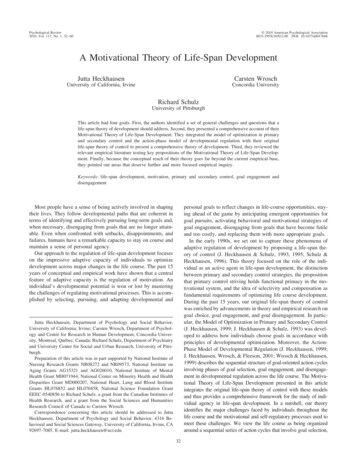
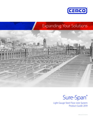
Overview Sure-Span Steel ThicknessMinimum Base Metal Thickness (mil)Design Thickness (in.)1Minimum Thickness (in.)1, 2Color 538"0.0677"0.0966"YellowGreenOrangeRed(1.15 mm)(1.44 mm)(1.81 mm)(2.58 mm)(1.09 mm)(1.37 mm)(1.72 mm)(2.45 mm)1) Uncoated steel thickness. Thickness is for carbon sheet steel.2) M inimum thickness represents 95% of the design thickness and is the minimum acceptable thickness delivered to the job site, based on Section A4.3 of the AISI S100-2012.Detail of SSCJ Punch-OutsSSCJ Punch-Out DimensionsSection725SSCJ175 - XX800SSCJ175 - XXL1 (in.)7-5/327-5/32L2 (in.)4-1/44-1/4Spacing Between Punch-Outs (in.)4848925SSCJ175 - XX1000SSCJ200 - XX1125SSCJ175 - XX1200SSCJ200 - XX1400SSCJ200 - 48104848484848CEMCO assumes no liability for failure resulting from the use of its drawings, or for failure resulting from the use of alternate materials, or improper application or installation. This drawing is supplied solely to assist inthe selection and application of CEMCO products. This drawing is generic in nature and should not be used in design or construction without an independent evaluation by a qualified Architect or Engineer of Record.Sure-Span Product Guide www.cemcosteel.com 800.775.23623
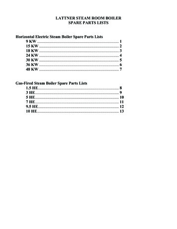
Overview Sure-Span Flange Joist BridgingDetail of SSTTDetail of Sure BridgingSure-Bridging for 1-3/4" Flange JoistsThickness(mils)43Part No.LengthJoistSpacing175SB431210"12" O.C.175SB431614"16" O.C.175SB4319217-1/4”19.2" O.C.175SB432422”24" O.C.Sure-Bridging for 2" Flange JoistsThickness(mils)43Part No.LengthJoistSpacing200SB43129-3/4"12" O.C.200SB431613-3/4"16" O.C.200SB4319217"19.2" O.C.200SB432421-3/4"24" O.C.CEMCO assumes no liability for failure resulting from the use of its drawings, or for failure resulting from the use of alternate materials, or improper application or installation. This drawing is supplied solely to assist inthe selection and application of CEMCO products. This drawing is generic in nature and should not be used in design or construction without an independent evaluation by a qualified Architect or Engineer of Record.4Sure-Span Product Guide www.cemcosteel.com 800.775.2362
Overview Sure-Span Definitions of Structural Properties NotationsDefinitions of Structural Properties NotationsSymbolIXIYSXSYRX, RYXOJDefinitionFull Moment of Inertia about the X axis (strong axis)Full Moment of Inertia about the Y axis (weak axis)Full Section Modulus about the X axisFull Section Modulus about the Y axisRadius of Gyration about the X and Y axis, respectivelyDistance between Centroid and Shear CenterSt. Venant’s Torsion ConstantSymbolCWROßANIXNMALLVALLDefinitionTorsion Warping ConstantPolar Radius of Gyration about the Shear CenterTorsional-Flexural ConstantCross-sectional Area at Punch-outMoment of Inertia at Punch-out about the X axisAllowable Moment for fully braced joistAllowable shearNotes1. The minimum yield strength, Fy, is 33 ksi for 18 gauge and 50 ksi for16, 14, and 12 gauge steel.2. Punch-out Depth 4.25” (web depth 7.25”, 8” ) 6.25” (web depth 9.25” , 10” and 11.25”) 8” (web depth 12”) 10” (web depth 14”)3. For Allowable Stress Design (ASD) method, use a factor of safety of1.67 for both moment and shear capacities. These factors of safetyare as per AISI S100-2016.4. Allowable moment, MALL, and shear, VALL, capacities for joists areobtained by applying factors of safety to the least nominal capacities (between full and net capacities).CEMCO assumes no liability for failure resulting from the use of its drawings, or for failure resulting from the use of alternate materials, or improper application or installation. This drawing is supplied solely to assist inthe selection and application of CEMCO products. This drawing is generic in nature and should not be used in design or construction without an independent evaluation by a qualified Architect or Engineer of Record.Sure-Span Product Guide www.cemcosteel.com 800.775.23625
Tables Sure-Span JoistStructural Properties of Sure-Span Joist: 7.25” to 14” WebSxen (in.3)EffectiveSectionPropertiesSxe (in.3)Vaf (k)Maf (k-in.)Allowable CapacitiesVap (k)ryn (in.)Iyn (in.4)rxn (in.)Ixn (in.4)ßRo (in.)Cw (in.6)J x 1000 (in.4)Xo (in.)Ry (in.)Rx (in.)Sy (in.3)Sx (in.3)Iy (in.4)Ix (in.4)Area (in2)Torsional PropertiesAn (in.2)Net Section Properties(at Punch-Outs)Map (k-in.)Gross Section PropertiesWeight (plf )Design Thickness, t (in.)SectionDesignationFlange Width, w (in.)Dim.7.25" Depth725SSCJ175-431.75 0.0451 1.826 0.537 3.998 0.225 1.103 0.175 2.728 0.647 -1.204 0.364 2.468 3.051 0.844 0.376 3.878 3.213 0.160 0.653 17.426 0.900 19.679 1.163 0.996 1.056725SSCJ175-541.75 0.0566 2.276 0.700 4.951 0.275 1.366 0.214 2.719 0.641 -1.190 0.715 3.003 3.037 0.846 0.466 4.796 3.209 0.195 0.648 32.771 1.637 37.575 2.316 1.255 1.311725SSCJ175-681.75 0.0713 2.841 0.836 6.124 0.334 1.689 0.260 2.707 0.633 -1.173 1.416 3.626 3.017 0.849 0.577 5.920 3.203 0.236 0.64 52.100 1.931 48.844 4.679 1.631 1.6338.00" Depth800SSCJ175-431.75 0.0451 1.941 0.571 5.069 0.231 1.267 0.176 2.980 0.636 -1.149 0.387 3.047 3.256 0.875 0.410 4.950 3.471 0.175 0.654 24.153 1.319 21.978 1.051 1.112 1.222800SSCJ175-541.75 0.0566 2.421 0.712 6.282 0.282 1.571 0.215 2.970 0.630 -1.136 0.760 3.710 3.242 0.877 0.508 6.127 3.472 0.214 0.648 45.750 2.433 42.027 2.091 1.404 1.528800SSCJ175-681.75 0.0713 3.023 0.889 7.777 0.344 1.944 0.262 2.958 0.622 -1.118 1.507 4.484 3.222 0.880 0.631 7.573 3.466 0.259 0.641 63.683 2.934 54.937 4.220 1.835 1.8939.25" Depth925SSCJ175-541.75 0.0566 2.661 0.783 8.951 0.293 1.935 0.217 3.382 0.612 -1.056 0.836 5.090 3.595 0.914 0.466 8.218 4.200 0.195 0.648 43.982 1.637 49.446 1.799 1.652 1.759925SSCJ175-681.75 0.0713 3.326 0.978 11.095 0.357 2.399 0.264 3.368 0.604 -1.039 1.658 6.159 3.576 0.916 0.577 10.153 4.195 0.236 0.64 69.243 1.931 65.091 3.627 2.174 2.195925SSCJ175-971.75 0.1017 4.666 1.372 15.297 0.472 3.308 0.350 3.339 0.587 -1.004 4.731 8.056 3.535 0.919 0.794 13.895 4.183 0.309 0.624 105.47 2.368 97.422 10.708 3.254 3.00410.00" Depth1000SSCJ200-542.00 0.0566 2.902 0.853 11.542 0.411 2.308 0.266 3.677 0.694 -1.196 0.911 8.211 3.929 0.907 0.537 10.809 4.488 0.294 0.74 62.946 2.433 56.383 1.660 1.883 2.1021000SSCJ200-682.00 0.0713 3.629 1.067 14.327 0.502 2.866 0.324 3.664 0.686 -1.178 1.809 9.973 3.909 0.909 0.666 13.385 4.483 0.357 0.733 88.863 2.934 76.371 3.345 2.551 2.6771000SSCJ200-972.00 0.1017 5.098 1.500 19.813 0.669 3.963 0.433 3.635 0.668 -1.142 5.170 13.154 3.868 0.913 0.921 18.411 4.471 0.473 0.716 127.030 3.798 114.860 9.862 3.836 3.68211.25" Depth1125SSCJ175-541.75 0.0566 3.046 0.896 14.516 0.307 2.581 0.220 4.025 0.585 -0.952 0.957 7.842 4.177 0.948 0.579 13.783 4.879 0.238 0.641 67.472 3.760 61.281 1.471 2.047 2.2541125SSCJ175-681.75 0.0713 3.811 1.121 18.023 0.373 3.204 0.268 4.010 0.577 -0.935 1.900 9.500 4.158 0.949 0.720 17.081 4.872 0.289 0.634 87.802 4.605 81.336 2.961 2.717 2.9331125SSCJ175-971.75 0.1017 5.358 1.576 24.935 0.494 4.433 0.355 3.978 0.560 -0.902 5.433 12.459 4.117 0.952 0.997 23.533 4.857 0.381 0.618 144.880 6.181 124.190 8.714 4.148 4.12712.00" Depth1200SSCJ200-542.00 0.0566 3.287 0.967 18.062 0.429 3.010 0.269 4.323 0.666 -1.087 1.032 12.315 4.507 0.942 0.551 16.312 5.442 0.301 0.74 78.565 2.698 57.295 1.102 2.292 2.6241200SSCJ200-682.00 0.0713 4.114 1.210 22.454 0.524 3.742 0.328 4.308 0.658 -1.070 2.050 14.973 4.487 0.943 0.684 20.215 5.437 0.366 0.732 111.840 3.268 93.622 2.770 3.127 3.3691200SSCJ200-972.00 0.1017 5.790 1.703 31.140 0.699 5.190 0.438 4.276 0.641 -1.036 5.871 19.795 4.446 0.946 0.947 27.854 5.425 0.485 0.716 160.150 4.274 143.110 8.145 4.78 4.64214.00" Depth1400SSCJ200-682.00 0.0713 4.600 1.353 32.997 0.541 4.714 0.331 4.939 0.632 -0.981 2.292 21.157 5.075 0.963 0.684 28.282 6.430 0.366 0.732 134.120 3.268 110.840 2.364 3.702 4.0401400SSCJ200-972.00 0.1017 6.481 1.906 45.872 0.721 6.553 0.442 4.905 0.615 -0.948 6.572 28.014 5.034 0.965 0.947 38.999 6.419 0.485 0.719 192.200 4.274 171.410 6.938 5.725 5.571NotationsNotesIxIySxSyRx, RyXoJCwRoßAnIxnM apVapM afVafSxeSxen1. The yield strength, Fy, is 33 ksi for 18 gauge and 50 ksi for 16, 14,and 12 gauge steel.6Full Moment of Inertia about the X axisFull Moment of Inertia about the Y axisFull Section Modulus about the X axisFull Section Modulus about the Y axisRadius of Gyration about the X and Y axis, respectivelyDistance between Centroid and Shear CenterSt. Venant’s Torsion ConstantTorsional Warping ConstantPolar Radius of Gyration about the Shear CenterTorsional-Flexural ConstantCross-sectional Area at Punch-OutMoment of Inertia at Punch-out about the X axisFully-braced Allowable Moment at Punch-outAllowable Shear at Punch-outFully-braced Allowable Moment at Full SectionAllowable Shear at Full SectionEffective Section Modulus about the X axis at Full SectionEffective Section Modulus about the X axis at Net Section2. Tabulated weight values based on 4’-0” o.c. punch-out progression.3. Punch-out Depth 4.25” (web depth 7.25”, and 8”)16.25” (web depth 9.25”, 10”, and 11.25”)18.00” (web depth 12”)10.00” (web depth 14”)4. For Allowable Stress Design (ASD) method, factors of safety of 1.67and 1.6 respectively, are used for moment and shear capacities asper AISI S100-2016.Sure-Span Product Guide www.cemcosteel.com 800.775.2362
Tables Sure-Span Rim TrackStructural Properties and Load Capacities of Sure-Span Rim Track: 7.25” to 14
4 Sure-Span Product Guide www.cemcosteel.com 800.775.2362 CEMCO assumes no liability for failure resulting from the use of its drawings, or for failure resulting from the use of alternate materials, or improper application or installation.