Transcription
GEORGE READ HALLUNIVERSITY OF DELAWARENEWARK, DELAWAREEric Alwine – Structural OptionSenior Thesis – April 2006Department of Architectural EngineeringThe Pennsylvania State University
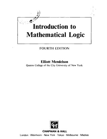
GEORGE READ HALLUNIVERSITY OF DELAWARENEWARK, DEPROJECT OVERVIEW:-5 STORIESAPPROX. 129,000 SQUARE FEETRESIDENTIAL HOUSING FOR STUDENTSCONSTRUCTION: MAY 2004-AUGUST 2005 27 MILLIONPRIMARY PROJECT TEAM:OWNER: THE UNIVERSITY OF DELAWAREARCHITECT: AYERS/SAINT/GROSSCONSTRUCTION MANAGER: WHITING-TURNERSTRUCTURAL ENGINEER: SKARDA & ASSOCIATESCIVIL ENGINEER: TETRA TECH, INC.CODE CONSULTANT: KOFFEL & ASSOCIATESM.E.P. AND FIRE PROTECTION: SEBESTA BLOMBERG& ASSOCIATESARCHITECTURAL:-GEORGIAN STYLELARGEST OF THREE BUILDINGS IN NEW-RESIDENTIAL COMPLEX“U-SHAPED”PEDESTRIAN BRIDGE TO MAIN CAMPUSSTRUCTURAL:FOUNDATION: CONTINUOUS & SPREAD FOOTINGSSUPERSSTRUCTURE: COLD FORMED METAL STUDSFLOOR: HAMBRO COMPOSITE FLOOR SYSTEMLATERAL SYSTEM: X-BRACED SHEAR WALLSENVELOPE: BRICK OR SIMULATED STONE FAÇADEMECHANICAL:-750 TON CHILLERVARIABLE AIR VOLUME UNITS50-5,000 CFMLIGHTING/ELECTRICAL:-480/277V & 208/120V3-PHASE, 4-WIRE350 KW DIESEL GENERATOR BACK-UPFLUORESCENT/HID LIGHTINGERIC ALWINESTRUCTURAL portfolios/ema134
Eric Alwine – Structural OptionGeorge Read Hall – University of DelawareDr. BoothbyThesis Final ReportApril 2006Table of Contents:Abstract . iExecutive Summary . 3General Building Information . 4Introduction. 5Building Envelope . 5Construction. 6Electrical . 7Lighting . 7Mechanical . 7Fire Protection . 8Telecommunications . 8Vertical Transportation . 9Existing Structural System. 10Problem Statement . 15Problem Solution. 17Alternate Structural System Design. 18Pre-cast Hollow Core Planks. 19Masonry Bearing Walls . 23Reinforced Masonry Shear Walls . 25Breadth Studies . 33Construction Management . 34LEED Certification . 36Conclusions and Recommendations . 46Acknowledgements . 48References. 49Appendix. 502
Eric Alwine – Structural OptionGeorge Read Hall – University of DelawareDr. BoothbyThesis Final ReportApril 2006Executive Summary:George Read Hall is a new five story dormitory on the campus ofThe University of Delaware. The building is approximately 129,000square feet. Its architecture is accentuated by its “U-shape” andGeorgian style. George Read Hall is the largest of three new buildingsbeing built to replace the existing Pencader residential complex.The existing structural system of George Read Hall is composed ofa Hambro composite floor system with light gauge metal stud bearingwalls. The lateral force resisting system is X-braced shear wallscomposed of light gauge metal straps. The roof structure is prefabricatedlight gauge metal trusses.This thesis project is an in depth study of an alternate structuralsystem. The goal of the alternate system is to find a more suitable lateralforce resisting system as well as a more economical overall system. Thisstudy investigated pre-cast hollow core planks, masonry bearing walls,and reinforced masonry shear walls. The results show lightweight 8”deep hollow core planks with a 2” concrete topping. Supporting theseplanks is 12” hollow blocks. The new lateral force resisting system iscomprised of grouted 8” blocks with #8 reinforcing bars. Prefabricatedlight gauge roof trusses are still the roof framing system.In addition to the depth study, two breadth studies were alsoperformed. A cost analysis of the new system showed a savings of 23,643 over the existing system. The new system can be constructed inabout the same amount of time. Hence, it can be concluded that thissystem is a very viable alternative. A study into LEED certification wasalso performed, and it can be concluded that a level of certification couldhave been achieved if properly incorporated into the original design.3
Eric Alwine – Structural OptionGeorge Read Hall – University of DelawareDr. BoothbyThesis Final ReportApril 2006Introduction:Building IntroductionBuilding Systems4
Eric Alwine – Structural OptionGeorge Read Hall – University of DelawareDr. BoothbyThesis Final ReportApril 2006Introduction:George Read Hall is one of three newstate of the art buildings being built on theUniversity of Delaware’s campus in Newark,Delaware. The new buildings are beingconstructed to replace the existing Pencadercomplex. George Read Hall consists of fiveBuilding Entrancefloors of dormitory style housing with double rooms sharing a bathroomas well as single room suites. The building also features laundry rooms,fully furnished lounge spaces, kitchen space,study rooms, and building support spaces.Housing approximately 500 beds, George ReadHall is the largest of the three new residentialbuildings. Also included in the building areInterior Lounge Spaceapartments for the hall directors and complexcoordinator. The exterior of the “U-shaped”building combines architectural features from the surrounding buildingsinto a Georgian styled look. The removal of the existing buildings willmake room for playing fields, tennis, basketball, and volleyball courts,and a pedestrian bridge from main campus to the new residentialcomplex.Building Envelope:The exterior walls are brick façade with many symmetrically placedwindows so that each room has a window. Each window is finished witha brick jack arch above and a simulated stone sill below. The fifth floor5
Eric Alwine – Structural OptionGeorge Read Hall – University of DelawareDr. BoothbyThesis Final ReportApril 2006is finished with dormers on each side of the building protruding from thegambrel style roof. The dormers are covered with metal paneling on thefront and shingles on the top, matching the rest of the roof. On thenorth end of the building, a two story curved wall complex lounge addsan additional space for students to relax or study. The exterior of thelounge is finished with simulated stone and several rows of bricks ateach floor level. Topping off the look of this complex lounge is a largestorefront system with one inch insulating glass units. Exterior bearingwalls of the building consist of metal stud framing with 2” rigidinsulation and an air space. The inside of the wall is finished will 5/8”gypsum board, while the outside is finished with brick or simulatedstone. The roof of George Read Hall is finished with asphalt shingles.Construction:The project began in May 2004 and took lessthan 15 months to complete. The buildingwas completed on time, and students wereable to move in for the fall semester 2005.George Read Hall cost approximately 27million. The construction process was toBuilding Siteoccur while interrupting as little as possible,including activities on the campus andsurrounding vegetation that was to remain. In addition, the process wasdesigned so that none of the beds in the existing Pencader complex wereremoved until the new beds were ready for use. Deliveries to the sitewere scheduled so as to minimize the amount of space used for storage6
Eric Alwine – Structural OptionGeorge Read Hall – University of DelawareDr. BoothbyThesis Final ReportApril 2006as well as the amount of time required for storage of materials andequipment.Electrical:George Read Hall is powered by both 480/277V and 208/120V.The larger power supply is needed to run appliances such as dryers andstoves, while the smaller source is needed to for outlets using smallerappliances. The elevators are powered by 480 volt, 60 Hz, 3 phase, wyedelta starting. Backup power is supplied by a diesel engine generatorthat will run at 350 kW for 17 hours.Lighting:As with a typical dormitory style building, various types of lightsand light fixtures were used. Typical sizes include 2’-0” x 2’-0”, 1’-0” x4’-0”, 2’-0” x 4’-0” as well as wall mounted lights providing direct lightingand direct/indirect lighting. Indirect lighting is also used. Manydifferent varieties of bulbs are used as well, including fluorescent andhigh intensity discharge. T4 and T8 fluorescent bulbs are used in doubleand triple tube fixtures. High-pressure sodium and metal-halide lampsare used in the HID fixtures. Emergency lighting is installed withbatteries and chargers.Mechanical:The construction of the three new buildings in the residentialcomplex required the installation of a new 750 ton chiller toaccommodate the building’s cooling needs. The air is supplied7
Eric Alwine – Structural OptionGeorge Read Hall – University of DelawareDr. BoothbyThesis Final ReportApril 2006throughout the building by variable air volume units. The air ismonitored by humidity sensors, air velocity sensors, and differentialpressure sensors. Airflow ranges from 50-5,000 FPM in most situations.The temperature can be controlled by electric thermostats that arelocated in each residential unit.Fire Protection:The building is equipped with automatic sprinkler systems. Thesprinkler systems are both wet-pipe and dry-pipe type systems. Sprayon fireproofing is used on the beams and columns. Exit enclosuresprovide a two hour fire rating, and occupancy separations provide a onehour fire rating. The fire protection system includes manual pullstations, audio devices, smoke detectors, heat detectors, and ductdetectors.Telecommunications:A security management system manages several of the buildingsystems. The system integrates access control, alarm monitoring, anddatabase management. Each room unit is equipped with phone andEthernet jacks as well as cable hookups for television. Twotelecommunications rooms are located on each floor and a maintelecommunications room is located in the basement. As with mostuniversities, access to the building will require authentication throughcard readers at the doors. Also, card access is required to operate theelevator.8
Eric Alwine – Structural OptionGeorge Read Hall – University of DelawareDr. BoothbyThesis Final ReportApril 2006Vertical Transportation:George Read Hall is equipped with two hydraulic passengerelevators running from the basement to the fifth floor. The elevators arerated at 3500 pounds and travel at 125 feet per minute. They areequipped with battery powered lowering. If the power fails, cars at a floorlevel will open their doors and shut down. Cars between floors will belowered to a pre-selected floor, open their doors, and shut down.9
Eric Alwine – Structural OptionGeorge Read Hall – University of DelawareDr. BoothbyThesis Final ReportApril 2006Existing Structural System10
Eric Alwine – Structural OptionGeorge Read Hall – University of DelawareDr. BoothbyThesis Final ReportApril 2006Existing Structural System:The existing floor system in George Read Hall is composed of aHambro composite floor system. This system uses 14” deep 50 ksi steeljoists working compositely with a 23/4” concrete slab. The joists arespaced at 4’-11/4” on center and typically span 23’-6” with an interiorspan of 6’-0” for the corridor. Typical bays are shown on pages 13 and14.Bearing walls are 16 gauge, 50 ksi cold formed metal studs. Thefirst floor is supported with 3-6” studs @ 16” on center. A typical bay is26’-8” x 23’-6”. Interior first floor framing consists of wide flange beamsof various sizes. The first floor interior framing differs from the upperfloors due to the need for more open space as required by the lounges.The second floor metal stud framing consists primarily of 3-6” studs @16” on center. Framing under the second floor hallway is wide flangebeams, with the typical size being a W14x53. These interior hallwaybeams are located on each side of the 6’-0” wide hallway. The interiorbeams are replaced by metal stud bearing walls under the hallway in thethird though fifth floor framing. The third through fifth floor framing isvery similar. The third floor bearing walls consist mainly of 2-6” studs @16” on center. The fourth and fifth floor bearing walls are built with 1-6”stud @ 16” on center. Roof framing on George Read Hall consists ofprefabricated light gauge metal trusses at a maximum of 4’-0” on centerwith 11/2” 22 gauge galvanized metal deck. The roof trusses span 54’-0”with two intermediate supports located 23’-6” from each exterior wall.The foundation is comprised of a combination of continuous andspread footings. The continuous footings range from 3’-0” wide to 7’-0”wide and are 1’-0” deep reinforced with continuous #5 bars. Fifteen11
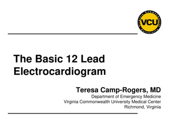
Eric Alwine – Structural OptionGeorge Read Hall – University of DelawareDr. BoothbyThesis Final ReportApril 2006different sizes of spread footings are used ranging from 3’-0” wide x 3’-0”wide x 1’-0” deep to 10’-0” wide x 10’-0” wide x 2’-3” deep. These spreadfootings carry the concentrated loads from the interior columns.Reinforcing for the spread footings are either #5 bars or #6 bars. Thefootings were designed using a soil bearing capacity of 4000 pounds persquare foot (psf). Basement walls are 1’-4” thick with #4@12 both waysin both faces. The basement floor of George Read Hall is a 5” thick slabon grade with 6 x 6 - W1.4 x W1.4 welded wire mesh. Slab control jointsare located so that there is a maximum of 40 feet in length along any oneside with a maximum uninterrupted concrete area of 1200 square feet.The lateral force resisting system of George Read Hall is X-bracedshear walls. The shear walls are located along typical bay lines. Firstfloor shear walls consist of X-bracing using 2-41/2” metal straps.The second and third floor shear walls are X-braced walls of 2-4” metalstraps. Fourth and fifth floor shear walls are 2-3” X-braced metal straps.The building footprint is shown on the following page, with the typicalbay area represented by the hatching. The shaded area on the typicalbay diagrams shows where the live load is 100 psf as required by code.The complete floor plans and building section can be seen in theappendix.12
Eric Alwine – Structural OptionGeorge Read Hall – University of DelawareDr. BoothbyThesis Final ReportApril 2006Figure 1: Building FootprintFigure 2: Typical Bay with Interior Beams13
Eric Alwine – Structural OptionGeorge Read Hall – University of DelawareDr. BoothbyThesis Final ReportApril 2006Figure 3: Typical Bay with Interior Bearing Walls14
Eric Alwine – Structural OptionGeorge Read Hall – University of DelawareDr. BoothbyThesis Final ReportApril 2006Problem Statement &Problem Solution15
Eric Alwine – Structural OptionGeorge Read Hall – University of DelawareDr. BoothbyThesis Final ReportApril 2006Problem Statement:A building must be designed to resist all applied forces inaccordance with the International Building Code (IBC). This includesgravity loads and lateral loads. The gravity loads are determined fromthe dead loads of the building and the live loads established in Table1607.1 of IBC. The lateral forces take into account the effects of windand seismic. These forces are also calculated in accordance with IBCwith references to ASCE 7. Because of load combinations set forth in theIBC, the building does not have to resist both wind and seismicconcurrently.After a review of Technical Assignment #2 it was prevalent thatseveral alternate floor systems were worth further investigation. Themost viable alternative floor system is pre-cast hollow core planks. Thiswas determined because it has the most advantages. It was concluded inTechnical Assignment #3 that the seismic forces control the design of thesystem. This differs from the original design in which the wind forceswere determined to control the design. Because of this, it was alsodetermined that the existing lateral system is not appropriately designedto resist these higher seismic forces. Therefore an alternate lateral forceresisting system will be designed.Although the system of X-braced shear walls is fairly simple in thescheme of lateral resisting systems, the irregular shape of the buildingrequires an analysis beyond the scope of my educational experiencesthus far. The determination of the direct and torsional shear forces ismore complex than in a rectangular or more regularly shaped building.Therefore, the design of an alternate lateral force resisting system willexpand my experiences in structural engineering. Additionally,16
Eric Alwine – Structural OptionGeorge Read Hall – University of DelawareDr. BoothbyThesis Final ReportApril 2006introducing a new lateral system would not be appropriate with theexisting gravity load resisting system. As a result, a redesign of thebearing walls system will also be done.One of the most important things to consider when designingbuildings is to make it as economical as possible. Because of this, it isvery critical to investigate different systems.Problem Solution:The solution to this is to design an alternate system and compareit to the original design. The alternative system being considered in thisproposal is a load bearing masonry system as well as masonry shearwalls. Also, a new floor system of pre-cast hollow core planks will bestudied. The alternate systems will then be compared to the originaldesign to determine whether it is a considerable alternative.17
Eric Alwine – Structural OptionGeorge Read Hall – University of DelawareDr. BoothbyThesis Final ReportApril 2006Depth Study:Alternate Structural SystemDesign18
Eric Alwine – Structural OptionGeorge Read Hall – University of DelawareDr. BoothbyThesis Final ReportApril 2006Pre-cast Hollow Core Planks:The floor system of the building must be designed to resist thegravity loads applied from both the dead load and live load. The deadload consists of the total weight of the materials as well as asuperimposed load. Hollow core planks were selected because of theirmany advantages. The construction process for these planks is fairlysimple, allowing it to be done quickly. They are very durable and fireresistant. Also, they are manufactured with high strength concrete,giving them excellent loading capacity. The disadvantage of hollow coreplanks in comparison to a Hambro composite system is that it makes thetotal building weight higher. This added weight increases the seismicforces on the building.The design floor load calculation is shown below. Thesuperimposed load accounts for furniture and other permanent fixtures.The live load accounts for the load from the occupants.Superimposed Dead Load 25 psfLive Load 40 psfTotal Load 1.2(25) 1.6(40) 94 psfUsing the PCI Design Handbook’s provided load tables for hollow coreplanks, it was determined that 4’-0” wide x 8” deep lightweight plankswith a 2” normal weight concrete topping are sufficient. The reinforcingfor these planks is 6-3/8” straight pre-stressing strands located 11/2” upfrom the bottom of the planks. The typical plank cross section is shownon the following page along with the corresponding load tables.Lightweight concrete was used for this design because it decreases the19
Eric Alwine – Structural OptionGeorge Read Hall – University of DelawareDr. BoothbyThesis Final ReportApril 2006total weight of the building. Lightweight 8” planks are actually lighterthan 6” normal weight planks. In addition to less weight, less reinforcingis needed because of the added depth.Figure 4: Hollow Core Plank Design Table20
Eric Alwine – Structural OptionGeorge Read Hall – University of DelawareDr. BoothbyThesis Final ReportApril 2006The typical exterior bearing wall detail is shown below.Figure 5: Exterior Bearing Wall DetailThe interior plank bearing detail is different on parts of the second floorthan it is on the upper floors. Some of the second floor planks bear onwide flange steel beams along the corridor. This is because more openspace is required on the floor below. The rest of the planks aresupported by interior load bearing masonry walls. The two typicalinterior bearing wall details are shown on the next page.21
Eric Alwine – Structural OptionGeorge Read Hall – University of DelawareDr. BoothbyThesis Final ReportApril 2006Figure 6: Interior Bearing on MasonryFigure 7: Interior Bearing on Wide Flange Beam22
Eric Alwine – Structural OptionGeorge Read Hall – University of DelawareDr. BoothbyThesis Final ReportApril 2006Masonry Bearing Wall System:The bearing walls for George Read Hall are located around theexterior of the building as well as along the interior corridor in order tosupport the hollow core planks. The walls were designed using theempirical design method. In order to design using this method, severalcriteria must be met:-length/width 4:1-Design wind speed 110 mph-Seismic Design Category A, B, C-height/thickness 18The exterior walls have a tributary width of 11’-4”. The interior wallshave the same 11’-4” tributary width as well as a 3’-0” width from thecorridor. The final summarized design calculations are shown below.The final wall stresses are in pounds per square inch.Exterior Wall:Floor No. Plank Size Self-weight Total DL Live Load54328" 28" 28" 28" 2686868689393939340404040Load fromLoad fromEstimatedsupportedWall load Wall Stresswall abovewall nterior Wall:Floor No. Plank Size Self-weight Total DL Live Load54328" 28" 28" 28" 2686868689393939340404040Load from EstimatedCorridor Load fromsupportedwallLive Load wall 7691829.55551007153.51829.555523Wall loadWallStress2384.547697153.5953816.633.149.766.2
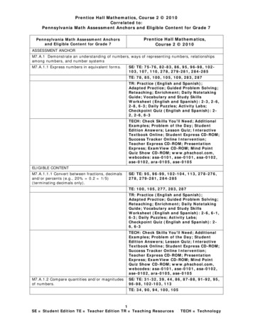
Eric Alwine – Structural OptionGeorge Read Hall – University of DelawareDr. BoothbyThesis Final ReportApril 2006These calculated wall stresses were then compared to the empiricaldesign method allowable compressive stresses in the National ConcreteMasonry Association TEK-Notes. The tables shown are for 12” hollowblocks. Calculations were also done for hollow 8” blocks as well asgrouted 8” blocks. It was determined that the compressive stresses onthe hollow 8” blocks exceeded the allowable values. Grouted 8” blockspresented a possible solution from a strength perspective. However,grouting all of the cells creates sufficiently more labor costs. Because ofthis, hollow 12” blocks were chosen as a more economical solution. Theallowable stress values are shown in the figure below.Figure 8: Allowable Compressive Stresses24
Eric Alwine – Structural OptionGeorge Read Hall – University of DelawareDr. BoothbyThesis Final ReportApril 2006As seen in the figure on the previous page, the allowable compressivestress for masonry units with a 1500 psi unit strength is 100 psi for TypeN mortar and 115 psi for Type M or S mortar. Both of these values arehigher than the maximum calculated stress; therefore, Type N mortarshould be used because it is the cheapest. To help control shrinkageand other movements, hot-dipped, galvanized truss type wirereinforcement will be provided in every other course. Additionally, asshown in the hollow core plank details above, a course of bond beamblocks is required for bearing of the planks.As mentioned above, parts of the second floor framing consist ofwide flange beams due to open space on the first floor. Because of theadded weight of the upper floor masonry bearing walls, these beamsneeded to be resized to accommodate the new loads. As shown in Figure2, a W14x53 spans 13’-3” and frames into a W14x61 that transfers theload into the supporting columns. After applying the new loads, theW14x53 needs to be increased to a W14x61. The W14x61 support beamdoes not need to be increased in size.Reinforced Masonry Shear Walls:The existing lateral resisting system consists of X-braced shearwalls. The walls are cold formed metal studs with 16 gauge, 50 ksi metalstraps. Shear walls are located on each side of the double loadedcorridor. The typical distance between walls is 26’-8”. At the fifth andfourth floors, the shear walls are constructed with 2-3” straps. 2-4”straps are used on the third and second floor, and 2-41/2” straps areused on the first floor. The typical shear wall details are shown on thenext page.25
Eric Alwine – Structural OptionGeorge Read Hall – University of DelawareDr. BoothbyThesis Final ReportApril 2006Figure 9: Existing Shear Wall DetailAs seen on the details, the vertical edge members of the shear walls aremetal studs. The straps are welded to the vertical studs with a 1/8” thickfillet weld. This shear wall system acts virtually as a vertical cantileveredtruss.It was previously determined that the seismic forces control thelateral force resisting system design. This becomes even more evident inthe new system because of the added weight of the masonry system. Theseismic story forces are calculated in the following table. More detailedseismic calculations can be seen in the appendix.26
Eric Alwine – Structural OptionGeorge Read Hall – University of DelawareDr. BoothbyThesis Final ReportApril 4481.6Shear23.43182.33327.81426.86481.6In addition to changing the shear walls from X-braced metal straps toreinforced masonry shear walls, the number of shear walls was reduced.Decreasing the number of shear walls on each floor helps to lower thecost because grouting and reinforcing is not required in walls notdesigned to resist shear.Figure 10: Existing Shear Wall Layout27
Eric Alwine – Structural OptionGeorge Read Hall – University of DelawareDr. BoothbyThesis Final ReportApril 2006Figure 11: New Shear Wall LayoutThe use of four shear walls in each wing helps to maintain that thebuilding acts rigidly under lateral loads. Also, the placement of the wallswas chosen to give the greatest resistance to torsional shear.The story shears are distributed to the shear walls according to therigidities of the walls. The rigidities were calculated according to thefollowing equation:R (Et)/(4(h/l)3 2.78(h/l)), where-E modulus of elasticity-t thickness of the wall-h height of the wall-l length of the wall28
Eric Alwine – Structural OptionGeorge Read Hall – University of DelawareDr. BoothbyThesis Final ReportApril 2006After distributing the story forces to the shear walls, the critical shearwall loading was determined. The design loading is shown below.Figure 12: Design Shear Wall LoadingThese shear walls must be designed to resist the direct shear forces aswell as the moment created by the shear forces. The greatest shear forceand resulting moment is created at the base of the building.V 94.3 kipsM 3023 ft-kipsThe design process began by assuming 8” grouted concrete masonryunits. The shear stress in the masonry is determined from ACI 530-02Structural Design Provisions section 2.3.5.2.1:fv V/(bd)fv (94,300 lb.)/((7.625 in.)(22.67 ft.)(12 in/ft)) 45.5/1.33 34.1 psi29
Eric Alwine – Structural OptionGeorge Read Hall – University of DelawareDr. BoothbyThesis Final ReportApril 2006The 1.33 factor takes into account an allowable stress increase from thecode. The allowable shear stress is determined from section 2.3.5.2.2(b)of ACI 530-02. This allowable stress is based upon the ratio of M/(Vd).Where M/(Vd) 1, Fv (f’m) but not to exceed 35 psi. This allowableshear stress is greater than the calculated stress in the masonry.Therefore, no shear reinforcement is needed, and 8” grouted blocks canbe used.As previously mentioned, the walls must also be designed to resistthe moment created by the shear forces. This is accomplished byproviding vertical flexural reinforcement. Thus, the shear walls act asrectangular beams in order to resist the moments. A sample calculationis shown below.fs M/(Asjd); Assume, j 0.85, d 0.8lSolving for As gives a trial steel area of 6.13 in2. Thus, try 8-#8 bars.d 240 in.ρ 0.0035n 21.5k 0.32j 0.893fs 3023(12000)/(6.32(0.893)(240)) 26,782 psifm (2(3023)(12000))/(7.625(0.893)(0.32)(240)2) 578 psiFs 24,000(1.33) 32,000 psiFm 1/3f’m 500(1.33) 666 psi30
Eric Alwine – Structural OptionGeorge Read Hall – University of DelawareDr. BoothbyThesis Final ReportApril 2006Both of the
a Hambro composite floor system with light gauge metal stud bearing walls. The lateral force resisting system is X-braced shear walls composed of light gauge metal straps. The roof structure is prefabricated light gauge metal trusses. This thesis project is an in depth study of an alternate structural system.