Transcription
Structural Design of Composite Bladesfor Wind and Hydrokinetic TurbinesDanny Sale and Alberto AlisedaNorthwest National Marine Renewable Energy CenterDept. of Mechanical EngineeringUniversity of WashingtonFeb. 13, 2012
Outline Previous Work–coupled aero-structural optimization (HARP Opt code)–simple structural model Newly Developed Structural Analysis Tool (CoBlade)–methodology & applications Structural Optimization–problem formulation–design of composite blade for tidal turbine Recommended Future Work2
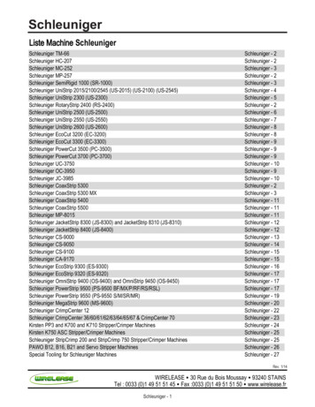
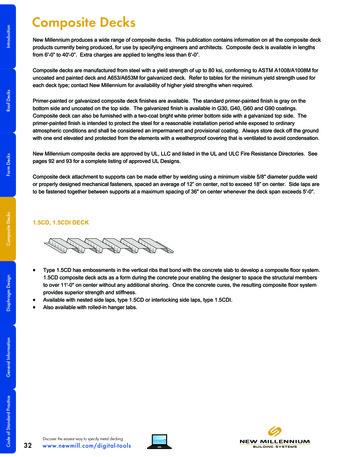
Previous Work: HARP OptHorizontal Axis Rotor Performance Optimization given:turbine & environmental specifications optimizes: blade shape, rotor speed & blade pitch control satisfying: maximum Annual Energy Production (AEP)performance constraints (power, cavitation, 40353025201510500.025ωmax201510ωminRotor SpeedBlade Pitch0.00.51.01.52.0flow speed (m/s)32.53.050
Previous Work: HARP OptSimple Structural Model Thin-shelled cantilever beam One material w/ isotropic properties Bending strain is only constraint Shell thickness is only design variableBending Strain:4
Previous Work: HARP OptCoupled Aerodynamic-Structural Optimization maximize energy production & minimize blade mass genetic algorithm identifies set of Pareto-efficient designs5
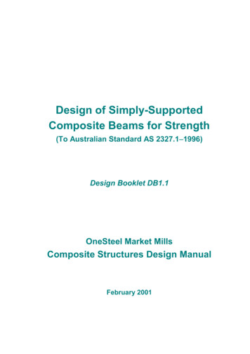
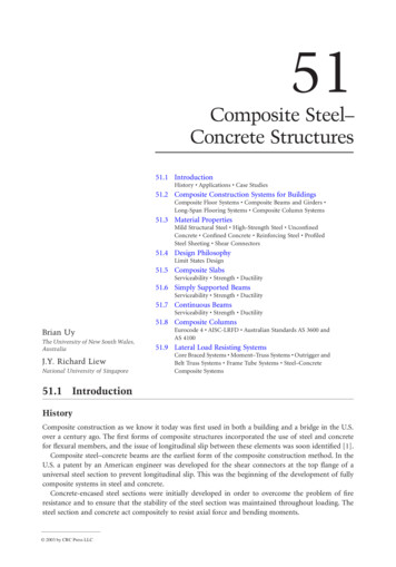
Moving Forward: Structural DesignDevelop a tool capable of modeling realistic composite bladesImage: www.Gurit.com6
Overview of CoBlade softwareStructural Analysis and Design of Composite Blades realistic modeling of composite blades– arbitrary topology & material properties computes structural properties– stiffnesses: bending, torsional, axial– inertias: mass, mass moments of inertia– principal axes: inertial/centroidal/elastic principal axes– offsets: center-of-mass, tension-center, shear-center structural analysis tool– arbitrary applied loads & body forces– recovery of 2D lamina-level strains & stresses– blade deflection & modal analysis– linear buckling analysis optimization of composite layupImage: replica of Sandia SNL100-00 wind turbine blade using CoBlade7
MethodologyClassical Lamination Theory Euler-Bernoulli beam model shear flowClassical Lamination Theory (CLT) describes mechanical response of laminated platesextensional stiffnessbending stiffnesscoupling stiffnessImage: G.S. Bir. “PreComp User’ Guide”8
MethodologyComposite Euler-Bernoulli Beam and shear flow approach describes global mechanical behavior of composite beamf3sf1f4f2Convert Beam Stresses into Equivalent Plate Loads recover 2D strains & stress at lamina level9
MethodologyLinear Buckling Analysis pinned boundary conditions (conservative) contributions from panel stiffness, curvature, thickness, & widthshear web panelstop/bottom surface panelsModal Analysis BModes: Rotating Beam Coupled Modes (NREL code)beam divided into finite elements[1] G.S. Bir, 2005. “User’s Guide to BModes: Software for Computing Rotating Beam Coupled Modes,” NREL TP-500-38976, Golden, CO: NationalRenewable Energy Laboratory.10
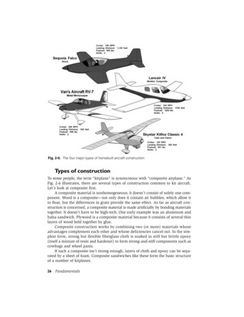
Optimization: Composite Layuproot build-uptransition transitionto sparto LEPLEPsparMaterial oreTEP-coreweb-shellweb-coretransitionto TEPMaterial Properties: Failure yCτ12,yTEPComposite Layup all laminates balanced & symmetric high & low pressure surfaces symmetric identical shear web laminatesshear websblade tip11
Optimization: Design VariablesDesign Variables spar-cap width at inboard & outboard stations lamina thicknesses along blade length12
Optimization: Objectives & Constraintsminimize: BladeMass *penalty factors formaximum stresspenalty factors for bucklingunder compression & shearpenalty factor fortip deflectionpenalty factor for separationof blade freqs. & rotor freq.subject to:constraints ensurefeasible geometry13
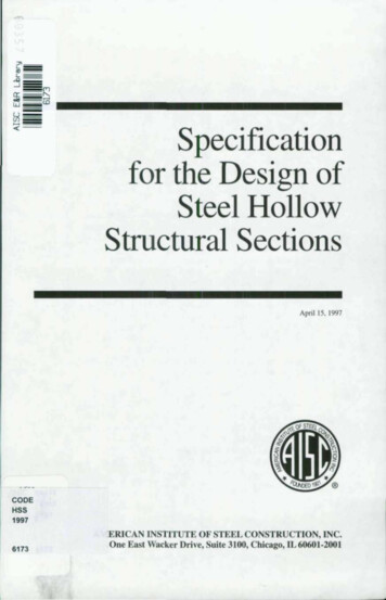
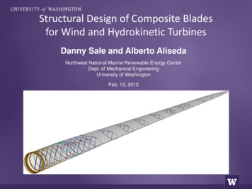
Optimization: Example DesignComposite Blade Design for Tidal Turbine hydrodynamic design: Department of Energy Reference Tidal Current Turbine, ref. [1] design loads: extreme operating conditions in Puget Sound, WA., ref. [2]30Root MomentBlade Pitch25turbulenteddy201200158001040050pressure (Pa)1600Blade Pitch (deg)Root Bending Moment (kN-m)200000.01.02.03.0Flow Speed (m/s)Image: ref [2][1] M.J. Lawson, Y. Li, and D.C. Sale, 2011. “Development and Verification of a Computational Fluid Dynamics Model of a Horizontal Axis TidalCurrent Turbine.” The 30th International Conference on Ocean, Offshore and Arctic Engineering.[2] G.S. Bir, M.J. Lawson, and Y. Li, 2011. “Structural Design of a Horizontal-Axis Tidal Current Turbine Composite Blade.” The 30th InternationalConference on Ocean, Offshore and Arctic Engineering.14
Optimization: ResultsBlade mass is minimized, final iteration satisfies all constraints (no penalties)CoBlade is fast: single evaluation: 1 sec, total optimization: 40 min15
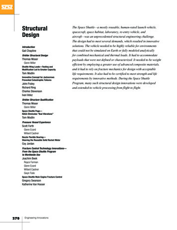
Optimization: Results-400-300normal stress, σzz (MPa)-1000100200shear stress, τzs (MPa)10152025-2005Top Surface Lamina Stress Failure Criteria300blade-shell material30root build-up materialspar-cap material00.2buckling criteria, R0.40.60.81core material16
Optimization: Results15010050flapbendingaxial26displacement stiffness (N-m ) x10 stiffness (N) x10602,000200Axial Stiffness1,500150Torsional 0.011st mode: 8.72 Hz-0.042nd mode: 18.32 Hz-0.093rd mode: 27.73 Hz-0.140.01.02.03.04.05.0blade length (m)176.07.08.09.0torsionalstiffness (N-m2) x106mass (kg/m)200
Conclusions Capable structural design tool, modeling of complex layups possible with CoBlade NOT a replacement for higher-fidelity FEM, but very effective for preliminary design work Limited validation studies–excellent agreement for analytically obtainable results–good agreement with ANSYS FEM model of tapered composite beam (collaboration w/ Penn. State)Future Work Preliminary results seem reasonable, but require further validation–anisotropic layups–buckling–lamina-level strains/stresses Repeat coupled aero-structural optimization (HARP Opt) with structural capabilities of CoBlade Include cross-coupled terms from CLT into beam equations Public release of CoBlade code & documentation18
Thank you! Questions?AcknowledgementsDr. Mark Tuttle (University of Washington)Matt Trudeau (Pennsylvania State University)This work has also been made possible by National Science Foundation Graduate Research Fellowship under Grant No. DGE-0718124Department of Energy, National Renewable Energy LaboratoryUniversity of Washington, Northwest National Marine Renewable Energy Center19
Extraelastic principal axesinertial principal axesXRcentroidal principal axesyscYRxscycmytcxtcxcm SCsectionreference ence plane (blade coordinate system x-axis)Rchord line20
web-shell τ web-core Material Legend: E 11 E 22 G 12 ν12 ρ σ 11,fT σ11,fC σ22,yT σ22,yC 12,y root build-up blade tip LEP spar TEP transition to LEP transition to TEP transition to spar shear webs Material Properties: Failure Stresses: Composite Layup all laminates balanced & symmetric high & low pressure surfaces symmetric